Surface Concept MCPD40 User manual

1-Channel MCP Detector MCPD40
1-Channel MCP Detector
MCPD40
(Release 006)
Manual

21-Channel MCP Detector MCPD40 Manual | Surface Concept GmbH
Surface Concept GmbH
Am Sägewerk 23a
55124 Mainz
Germany
phone: +49 6131 62716 0
fax: +49 6131 62716 29
email: info@surface-concept.de
web: www.surface-concept.de
All rights reserved. No part of this manual may
be reproduced without the prior permission
of Surface Concept GmbH.
1-Channel MCP Detector
MCPD40 Release 006
Manual Version 2.1
Printed on 2019-08-16

3
1-Channel MCP Detector MCPD40 Manual
1-Channel MCP Detector MCPD40 Manual | Surface Concept GmbH
1 Table of Contents
1 Table of Contents ......................................................................................................................3
2 Introduction................................................................................................................................4
2.1 General Information..........................................................................................................4
2.2 Safety Instructions .............................................................................................................4
2.3 General Overview of the System..................................................................................5
3 Installation...................................................................................................................................6
3.1 Initial Inspection.................................................................................................................6
3.2 Installation............................................................................................................................6
3.2.1 Mounting the MCPD Detector............................................................................6
3.2.2 Cabling and High Voltage ....................................................................................7
4 Operation of the MCPD40 .....................................................................................................8
4.1 Getting Started ...................................................................................................................8
4.1.1 “Start Up“ Procedure ..............................................................................................8
4.1.2 Dark Count Rate Measurement..........................................................................9
4.1.3 Standard Detector Measurement......................................................................9
4.2 Standard Operation Procedure.................................................................................. 10
4.3 Bake Out Procedure....................................................................................................... 10
5 MCP Detector Layout ........................................................................................................... 11
5.1 MCPD40 - Vacuum Wiring ........................................................................................... 11
5.2 Filterbox............................................................................................................................. 12
6 Microchannel Plate ............................................................................................................... 13
6.1 Specications................................................................................................................... 13
6.2 Storage............................................................................................................................... 13
6.3 Handling............................................................................................................................ 13
6.4 Operation.......................................................................................................................... 14
6.5 MCP Lifetime and Operation Voltage ..................................................................... 14
6.6 MCP Degase Procedure................................................................................................ 17
6.7 Replacement.................................................................................................................... 17
7 Technical Data......................................................................................................................... 18
8 List of Figure ............................................................................................................................ 19

41-Channel MCP Detector MCPD40 Manual | Surface Concept GmbH
2 Introduction
2.1 General Information
This manual is intended to assist users in the installation, operation and maintenance of Release 006 of the
1-channel MCP detector MCPD40.
It is divided into 8 chapters. The chapter “Introduction” contains a brief description of the Detector. The
chapter “Installation” refers to installation and cabling. Chapter “Operation of the MCPD40” describes
the operation of the detector. The nal chapters contain amongst others technical details about the
microchannel plates and the MCP detector.
2.2 Safety Instructions
Please read this manual carefully before performing any electrical or electronic
operations. Strictly follow the safety rules given within the manual.
The following symbols appear throughout the manual:
Note
The“note symbol”marks text passages, which contain important information/hints about
the operation of the detector. Follow these information to ensure a proper functioning
of the detector.
The “caution symbol” marks warnings, which are given to prevent an accidentally
damaging of the detector or the readout system. Do NOT ignore these warnings and
follow them strictly. Otherwise no guarantee is given for arose damages.

5
1-Channel MCP Detector MCPD40 Manual
1-Channel MCP Detector MCPD40 Manual | Surface Concept GmbH
2.3 General Overview of the System
The Surface Concept MCPD40 R006 is a 1-Channel MCP Detector.
It consist of a chevron microchannel plate stack and a detector anode. MCP pulses are capacitively coupled
into the anode. The anode is a 50Ohm matched system and signal readout is realized close to ground via a
coaxial cable and connector layout. The active detection area is 40mm.

61-Channel MCP Detector MCPD40 Manual | Surface Concept GmbH
3 Installation
3.1 Initial Inspection
Visual inspection of the MCPD40 is required to ensure that no damage has occurred during shipping.
Should there be any signs of damage, please contact your provider immediately.
3.2 Installation
The detector is packed under vacuum. Proceed as follows, to install it into your vacuum chamber:
• Vent the package carefully.
• Unpack the detector carefully.
• Before installing the detector to your chamber, check the front side of the MCP stack for particles.
3.2.1 Mounting the MCPD Detector
The microchannel plates in front of the detector should be protected from exposure to
particle contamination. Particles that stick to the plate can be removed by using a single-
hair brush carefully and/or with dry nitrogen. Reading the instructions “microchannel
plates” in Chapter 6 is strongly recommended.

7
1-Channel MCP Detector MCPD40 Manual
1-Channel MCP Detector MCPD40 Manual | Surface Concept GmbH
3.2.2 Cabling and High Voltage
The general connection scheme of the detector is shown in Figure 1.
HV Supply
MCP-F
MCP-B
SIG
Pulse
Processing
and
Readout
Electronics
Figure 1: Connection scheme of the MCPD40 R006.
• The detector holds two SHV connectors (labeled“MCP-B”and “MCP-F”) for the high voltage supply and
one BNC connector (labeled“SIG”) for the signal output.“MCP-B”connects the high voltage part of the
detector anode and the back side of the MCP stack (via an internal resistor) while“MCP-F” connects the
front side of the MCP stack.
Be sure that all voltages are settled to zero before connecting the high voltage cables to
the detector, otherwise serious damage to the detector can occur due to high voltage
sparks.

81-Channel MCP Detector MCPD40 Manual | Surface Concept GmbH
4 Operation of the MCPD40
4.1 Getting Started
• Follow this procedure when taken the detector to operation the rst time and after every venting.
• Finish the complete cabling as described in Chapter 3.
• Be sure, that the vacuum pressure at the detector is remarkably below 1E-6mbar, otherwise the
microchannel plates might be damaged by a local discharging (in general: the lower the pressure, the
longer the lifetime of the MCPs).
• Turn o all sources for electrons, ions, light or X-rays that might hit the detector.
4.1.1 “Start Up“ Procedure
Ion gauges and ion pump are both sources for electrons and ions. Ion pumps can also
be a source for X-rays. They can produce so many particles/X-rays that the detector is in
a complete overload, even when they are not facing the detector directly. This will wear
out the MCPs very fast. Turn o ion pumps and ion gauges before turning on the high
voltage of the detector.
• Turn on the high voltage carefully.The voltage increase should not exceed 400V per minute. A schematic
sketch on how to ramp the voltages during the “Start-Up” procedure is given Figure 2. The starting
operation voltage is specied in the specication sheet of the detector.
• Watch the vacuum pressure while increasing the high voltage; turn the voltages back, if an unusual
increase is observed in the pressure (indicator for high voltage sparking).
High voltage sparks may seriously damage the detector anode or the MCPs. Observe the
chamber pressure carefully every time the high voltage is turned on. Switch o the high
voltage immediately in case of a temporary pressure rise by an order of magnitude or
more. This indicates high voltage sparking.
If sparking occurs, turn down the high voltage immediately and wait some time (up to 5
min.). Start the“Start-Up”procedure again with an increased ramp time. Turn o the high
voltage completely, stop the procedure and call your provider for further assistance, if is
it not possible to reach the operation voltage without sparking.

9
1-Channel MCP Detector MCPD40 Manual
1-Channel MCP Detector MCPD40 Manual | Surface Concept GmbH
Figure 2: Schematic sketch on voltage ramping during“Start-Up”procedure.
Note
The detector starting operation voltage for “MCP-B” is given in the specication sheet.
Example: The “MCP-B” voltage is given in respect to the “MCP-F” voltage. A ramp time of 4min. should be
used to change the“MCP-B”voltage from 0 V to a target voltage of exemplary +1600V.
4.1.2 Dark Count Rate Measurement
• Check the detector output by means of any electronics and software or with an oscilloscope where the
input is terminated with 50Ohms.
• The dark count rate without any source should be as given in the specication sheet.
4.1.3 Standard Detector Measurement
• After nishing the dark count rate measurement with a satisfying result, you may now start carefully
with an electron or light source observing the detector output.
Turn o the high voltage before performing any changes of the cabling.

10 1-Channel MCP Detector MCPD40 Manual | Surface Concept GmbH
4.2 Standard Operation Procedure
Follow this procedure for all later operation starts, when the detector has already been operated in vacuum
and has not been vented in between.
• Finish the complete cabling as described in Chapter 3.
• Be sure, that the vacuum pressure at the detector is remarkably below 1E-6mbar, otherwise the
microchannel plates might be damaged by a local discharging (in general: the lower the pressure, the
longer the lifetime of the MCPs).
• Turn o all sources for electrons, ions, light or X-rays that might hit the detector.
• Turn up the high voltage carefully and stepwise within 2 - 3 minutes to the operation voltage. The
starting operation voltage is specied in the specication sheet of the detector.
• Watch the vacuum pressure while increasing the high voltage; turn the voltages back, if an unusual
increase is observed in the pressure (indicator for high voltage sparking).
High voltage sparks may seriously damage the detector anode or the MCPs. Observe the
chamber pressure carefully every time the high voltage is turned on. Switch o the high
voltage immediately in case of a temporary pressure rise by an order of magnitude or
more. This indicates high voltage sparking.
If sparking occurs, turn down the high voltage immediately and wait some time (up to 5
min.). Start the“Start-Up”procedure again with an increased ramp time. Turn o the high
voltage completely, stop the procedure and call your provider for further assistance, if is
it not possible to reach the operation voltage without sparking.
• Now you may start carefully with an electron source observing the detector output.
Turn o the high voltage before performing any changes of the cabling.
4.3 Bake Out Procedure
Note
The detector starting operation voltage for “MCP-B” is given in the specication sheet.
The maximum allowed temperature for the detector is 150°C. Do not exceed this
temperature.
• Windows and feedthroughs should be wrapped with aluminum foil, to protect them from rapid
temperature changes.
• The use of heating tapes and jackets is not recommended, due to danger of local overheating.
• Do not remove the blankets until the entire system has thoroughly cooled o.
• Do not operate the detector before the temperature has returned to ambient conditions.

11
1-Channel MCP Detector MCPD40 Manual
1-Channel MCP Detector MCPD40 Manual | Surface Concept GmbH
5 MCP Detector Layout
5.1 MCPD40 - Vacuum Wiring
The MCP detector MCPD40 consist of a detection area, dened by the MCP holders and the detector anode.
The front side of the detector anode is on high voltage potential, while the signal readout is realized close
to ground potential (in respect to the high voltage of the MCPs). A pulse coupling layer is used to isolate
the high voltage from the ground potential within a“sandwich”layer system of the detector anode.
Figure 3: Layout of the HV connections and photos of the single
detector elements.
The internal connection of the high voltage for MCPD40 R006 is given schematically in Figure 4.
Figure 4: Internal connection of the high voltage potentials (schematic) for the R006.
Note
Theresistancebetween“MCP-F”and“MCP-B”(resistanceofMCPstackandinternalresistor)
should be in the range of 100 – 400MΩ (the exact values are given in the specication
sheet of the detector). The resistance between “MCP-F” and “SIG” and“MCP-B” and “SIG”
should be unlimited.

12 1-Channel MCP Detector MCPD40 Manual | Surface Concept GmbH
5.2 Filterbox
The MCPD40 might come with an additional lterbox for the signal output to minimize noise eects on the
signal line, which comes from external sources.
Connect the lterbox with the short cable to the BNC feedthrough of the MCPD40 and connect your signal
readout to the BNC connector of the lterbox.
Figure 5: Filterbox.

13
1-Channel MCP Detector MCPD40 Manual
1-Channel MCP Detector MCPD40 Manual | Surface Concept GmbH
6 Microchannel Plate
6.1 Specications
Please check the specication sheet of the DLD for the exact MCP specications.
6.2 Storage
Because of their structure and the nature of the materials used in manufacture, care must be taken when
handling or operating MCPs. The following precautions are strongly recommended:
• The most eective long-term storage environment for an MCP is an oil-free vacuum.
6.3 Handling
• Packages should be opened only under class 100 Laminar ow cleanroom conditions.
• Personnel should always wear clean, talc-free, class 100 clean-room compatible, vinyl gloves when
handling MCPs. No physical object should come into contact with the active area of the wafer. The MCP
should be handled by its rims, there is no solid glass border! Use clean degassed tools fabricated from
stainless steel, Teon™ or other ultra-high vacuum-compatible materials. Handling MCPs should be
limited to trained, experienced personnel.
• MCPs without solid glass border should be handled very carefully with great care taken to contact the
outer edges of the plate only.
• The MCP should be protected from exposure to particle contamination. Particles which become axed
to the plate can be removed by using a very pure and low pressure air ow such as from a clean rubber
bellows.
• The MCP should be mounted only in xtures designed for this purpose. Careful note should be taken
of electrical potentials involved.
Voltages must not be applied to the device while at atmospheric pressure. The pressure
should be 1E-6mbar or lower at the microchannel plate before applying voltage.
Otherwise, damaging ion feedback or electrical breakdown will occur.

14 1-Channel MCP Detector MCPD40 Manual | Surface Concept GmbH
6.4 Operation
• A dry-pumped or well-trapped/diusion-pumped operating environment is desirable. A poor vacuum
environment will most likely shorten MCP life or change MCP operating characteristics.
• A pressure of 1E-6mbar or better is preferred. Higher pressure can result in high background noise or
even to damaging due to ion feedback or to an electrical breakdown.
• Apply voltages as dened in Chapter 4. If uctuations appear, damage or contamination should
be suspected and the voltage should be turned o. The assembly should then be inspected before
proceeding.
• Voltage across single MCPs should not exceed the maximum voltage given in the specication sheet of
the detector. Higher potentials may result in irreversible damage.
• MCPs can be degraded by exposure to various types of hydrocarbon materials which raise the work
function of the surface, causing gain degradation.
• Operation at higher temperatures (> 50°C) will cause gain degradation.
• MCPs may degas for quite a while during operation. The pressure increase also depends on the number
of initial particles given to the MCP (e.g. pressure increase from 5E-10mbar up to 5E-9mbar for a new
chevron MCP stack). A degas procedure for MCPs is described in Chapter 6.6.
6.5 MCP Lifetime and Operation Voltage
The lifetime of the MCPs is determined by the MCPs gain degradation over time, whereas the gain
degradation is a function of the extracted output charge. Therefore the lifetime of the MCPs strongly
depends on the count rate applied to the detector over time.
The typical gain degradation of a MCP is shown in Figure 6 as a function of extracted output charge in
terms of coulombs per square centimeter.
Figure 6: Typical gain degradation of MCPs as function of the extracted output charge.

15
1-Channel MCP Detector MCPD40 Manual
1-Channel MCP Detector MCPD40 Manual | Surface Concept GmbH
After an initial burn-in period, in which the detector gain changes as a result of electron induced chemical
allocation together with degassing residual gas molecules from the inside of the channels, the MCP
performance is very stable over a large amount of extracted output charge. The MCP gain is also a function
of the detectors operation voltage. Therefore gain degradation can always be compensated by increasing
the detector voltage.
Detector delivery will still happen with the MCPs operating within the burn-in period, although the detector
has been operated for some longer time with highest count rates during the test phase, Therefore gain
degradation will be still signicant in the rst year of operation (or even longer, depending on applied count
rates) and becomes obvious by a decline of the detector performance. Therefore it will become necessary
to increase the operation voltage from time to time. Voltage increase should always be made in small steps
(typically 50V). There is a recommended maximum operation voltage, to which the detector voltage can
be increased to compensate gain degradation over time. This voltage is given in the specication sheet of
each detector.
A typical behavior of the detector voltage increase over time to compensate gain degradation is given
schematically in Figure 7.
Figure 7: Schematic plot of increasing the operation voltage to compensate gain degradation over
time as function of the extracted charge (all values are only exemplary).
Note
It is not unusual that the operation voltage must be increased several times especially in
the rst year of operation.
Typically, the nal operation voltage at the end of the burn-in period will be close to the recommended
maximum operation voltage. An increase of the operation voltage above the recommended maximum
operation voltage is in principal possible and allowed, as long as there is no signicant increase in the dark
count rate, bright spots at the detection area and/or appearance of high voltage sparking.

16 1-Channel MCP Detector MCPD40 Manual | Surface Concept GmbH
Note
The operation voltage can be increased even above the recommended maximum
operation voltage. A safe and reliable operation will still be possible as long as there is
no increase in the dark count rate and/or no appearance of high voltage sparking.
It can be sucient to estimate the correct operation voltage by monitoring the detector results, when
increasing the voltage to compensate the gain degradation. The exact operation voltage can always be
determined by measuring a so called MCP curve.The MCP curve plots the detected count rate as a function
of the operation voltage. Do as follows to measure an MCP curve:
• Start the detector operation with a homogeneous illumination (as good as possible).
• Use an appropriate device to measure the count rate output of the detector.
• Decrease the operation voltage until the count rate of the detector is reduced to zero.
• Increase the operation voltage in steps of 50V until far above the last operation voltage (please respect
the recommended maximum operation voltage) or until the detector shows signicant artifacts.
Measure the count rate for each voltage step.
• Plot the measured count rate as a function of the operation voltage. This is the MCP curve. It should
show a change in the slope of the rising curve, which indicates the beginning of the area of operation.
• The new value for the operation voltage should be a bit above the position of the change in the slope.
Figure 8 shows an example of a MCP curve with the specied operation voltage. The MCP curve for
specifying the starting operation voltage for a detector can always be found in the specication sheet.
Figure 8: Example of MCP curve (for illustration only).

17
1-Channel MCP Detector MCPD40 Manual
1-Channel MCP Detector MCPD40 Manual | Surface Concept GmbH
The life time of MCPs can be very large, due to the high stability of the operation performance over a
large amount of extracted output charges after the burn-in period. The main reason for an often much
shorter operation time of the MCPs is an inhomogeneous irradiation of the MCPs. This is connected to a
locally (strong) dierent gain degradation, which results in an inhomogeneous detector response. Locally
dierent gains can still be compensated by increasing the operation voltage, but very often the increasing
voltage step must be much larger to reach again a homogeneous detector response.
Gain degradation also depends strongly on the environment in which the MCPs are being operated. Care
should be taken to prevent exposure to high concentrations of hydrocarbons and halogens. Also prevent
MCP operation at higher temperatures (> 50°C, e.g. respect an appropriate cooling phase after bake out).
Note
Strong inhomogeneous irradiation of the MCPs lead to strong locally dierent gain
degradation and to an inhomogeneous detector response, which is the main reason for
a shortened operation time of the MCPs.
6.6 MCP Degase Procedure
The eect of MCP outgasing can be reduced by running a degas procedure. To do so the detector must be
operated at a high count rates for a time period of some hours.
It is really important that the detector is irradiated homogeneously over the complete
active area. Otherwise the MCPs will degenerate at various positions dierently, which
will lead to an inhomogeneous at eld of the detector.
Operate the detector continuously. During the degas procedure the pressure increase should reduce
signicantly to an acceptable pressure range. Then switch to the nal application. The pressure increase
for a smaller count rate should now be much smaller. Unfortunately the degas procedure must be started
anew (to a certain extend) after each venting of the detector.
6.7 Replacement
Note
Contact your provider before performing a replacement.
Please contact your provider before performing any MCP replacement. We will provide you with a detailed
step by step description.
Please take care to note the orientation of the MCPs. The channels in the MCPs include a certain angle
against the surface normal to the plate and the MCPs must be mounted in a chevron conguration. All
parts of the detector, especially the MCPs should be handled with great care. The MCP surfaces are very
sensitive and should never be touched or scratched.

18
Active area:
Dark count rate (typ.):
Max. operation voltage (typ.):
HV connections:
Connections for signal:
Max. bake-out temperature:
Vacuum pressure range for operation:
MCPD40 R006:
40 mm
<10 counts per sec.
See Specication Sheet for detail
2 SHV connectors (MCP front, detector anode + MCP back)
1 BNC connector (50Ohm matched coaxial signal)
150°C
<1E-6 mbar
1-Channel MCP Detector MCPD40 Manual | Surface Concept GmbH
7 Technical Data

19
1-Channel MCP Detector MCPD40 Manual
8 List of Figure
Figure 1: Connection scheme of the MCPD40 R006................................................................................................................................................. 7
Figure 2: Schematic sketch on voltage ramping during“Start-Up” procedure..................................................................................................9
Figure 3: Layout of the HV connections and photos of the single detector elements................................................................................. 11
Figure 4: Internal connection of the high voltage potentials (schematic) for the R006.............................................................................. 11
Figure 5: Filterbox.................................................................................................................................................................................................................. 12
Figure 6: Typical gain degradation of MCPs as function of the extracted output charge........................................................................... 14
Figure 7: Schematic plot of increasing the operation voltage to compensate gain degradation over time as function of the
extracted charge (all values are only exemplary)....................................................................................................................................................... 15
Figure 8: Example of MCP curve (for illustration only)............................................................................................................................................. 16
1-Channel MCP Detector MCPD40 Manual | Surface Concept GmbH
Table of contents
Other Surface Concept Security Sensor manuals
Surface Concept
Surface Concept CEM 4230 User manual
Surface Concept
Surface Concept MCPD18 User manual
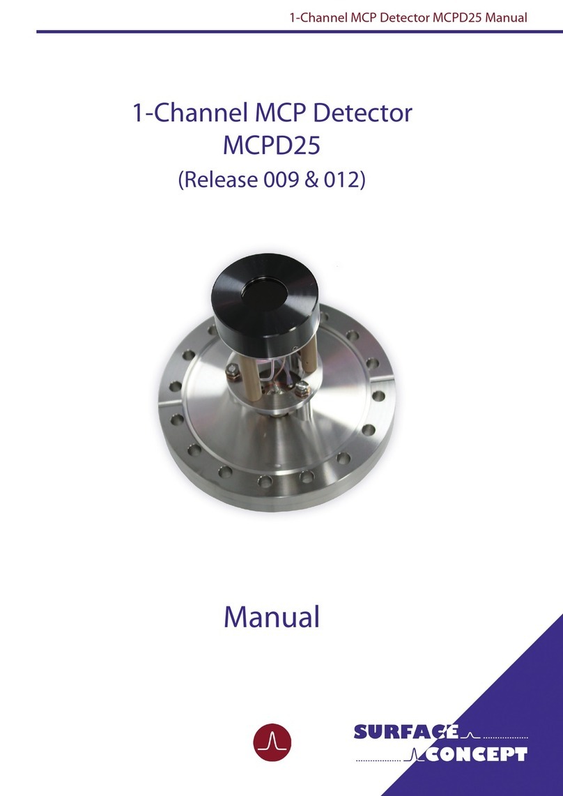
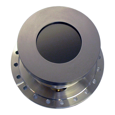
Surface Concept
Surface Concept MCPD25 User manual
Surface Concept
Surface Concept Delayline DLD 8080 User manual
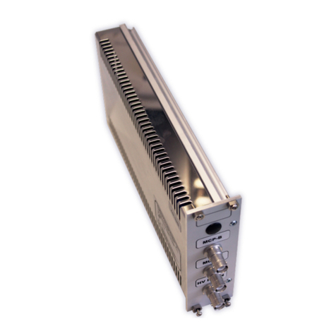
Surface Concept
Surface Concept HVPS User manual
Surface Concept
Surface Concept DLD4040 User manual
Surface Concept
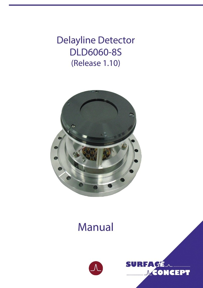
Surface Concept DLD6060-8S User manual

Surface Concept
Surface Concept Delayline DLD 8080 User manual
