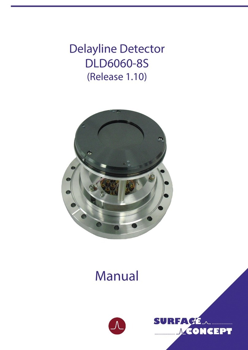
Surface Concept DLD4040 User manual

Delayline Detector DLD4040 Manual
Delayline Detector
DLD4040
(Release 2.55 & 3.54)
Manual

2DLD4040 R2.55 & R3.54 Manual | Surface Concept GmbH
Surface Concept GmbH
Am Sägewerk 23a
55124 Mainz
Germany
phone: +49 6131 62716 0
fax: +49 6131 62716 29
email: info@surface-concept.de
web: www.surface-concept.de
All rights reserved. No part of this manual may
be reproduced without the prior permission
of Surface Concept GmbH.
Delayline Detector DLD4040
Release R2.55 & R3.54
Manual Version 2.3
Printed on 2020-07-02

3
Delayline Detector DLD4040 Manual
DLD4040 R2.55 & R3.54 Manual | Surface Concept GmbH
1 Table of Contents
1 Table of Contents ................................................................................................................................................3
2 Introduction..........................................................................................................................................................5
2.1 General Information....................................................................................................................................5
2.2 Safety Instructions .......................................................................................................................................5
2.3 General Overview of the System............................................................................................................ 6
3 Installation............................................................................................................................................................. 7
3.1 Initial Inspection............................................................................................................................................... 7
3.2 Installation .......................................................................................................................................................... 7
3.2.1 Mounting of the Delayline Detector..........................................................................................7
3.2.2 Detector Orientation.......................................................................................................................8
3.2.3 Cabling and High Voltage..............................................................................................................9
3.2.4 Software Interface and Installation......................................................................................... 11
4 Operation of the DLD......................................................................................................................................13
4.1 Getting Started ...........................................................................................................................................13
4.1.1 “Start Up“ Procedure..................................................................................................................... 13
4.1.2 Dark Count Rate Measurement................................................................................................ 15
4.1.3 Standard DLD Measurement..................................................................................................... 16
4.2 Standard Operation Procedure.............................................................................................................16
4.2.1 Operation with MCP Front Side terminated to GROUND ............................................... 16
4.2.2 Operation of the Detector with the MCP Front Side connected to a Reference Voltage17
4.3 Bake Out Procedure.................................................................................................................................. 19
5 DLD - Principle of Operation.........................................................................................................................21
5.1 Basics of Delayline Detection................................................................................................................ 21
5.2 Basic Operational Modes of the Delayline Detector .................................................................... 22
5.2.1 2D(x, y) Area Detection................................................................................................................ 22
5.2.2 3D(x, y, t) Time Resolved Imaging............................................................................................ 22
5.3 Data Acquisition ........................................................................................................................................ 22
5.4 Working with the DLD - Important Details ...................................................................................... 23
5.5 MCP Outgassing during Operation .................................................................................................... 24
6 Delayline Detector Layout.............................................................................................................................25
6.1 Delayline Detector - Vacuum Wiring .................................................................................................. 25
6.2 Delayline Detector - Connection Ports.............................................................................................. 26

4DLD4040 R2.55 & R3.54 Manual | Surface Concept GmbH
7 Pulse Processing Electronics.........................................................................................................................29
7.1 Pulse Processing Electronics ACU 3.4.2............................................................................................. 29
7.1.1 Positions of the Discriminator Threshold Regulators ....................................................... 30
8 Micro Channel Plate (MCP)............................................................................................................................31
8.1 Specications.............................................................................................................................................. 31
8.2 Storage.......................................................................................................................................................... 31
8.3 Handling....................................................................................................................................................... 31
8.4 Operation..................................................................................................................................................... 32
8.5 MCP Lifetime and Operation Voltage ................................................................................................ 32
8.6 MCP Degase Procedure........................................................................................................................... 36
8.7 Replacement............................................................................................................................................... 36
9 Troubleshooting................................................................................................................................................37
10 Technical Data .................................................................................................................................................39
11 List of Figure.....................................................................................................................................................41

5
Delayline Detector DLD4040 Manual
DLD4040 R2.55 & R3.54 Manual | Surface Concept GmbH
2 Introduction
2.1 General Information
This manual is intended to assist users in the installation, operation and maintenance of Release Version
2.55 & 3.54 of the Delayline Detectors DLD4040. It is divided into 11 chapters. The chapter “Introduction”
contains a brief description of the DLD. The chapter “Installation” refers to installation and cabling, while
the chapter “Principle of Operation” explains the theory of operation of the DLD. 3 chapters describe
the technical details of the detector readout package and chapter “Operation of the DLD” describes the
operation of the DLD. The nal chapters contain amongst others technical details about the microchannel
plates and the delayline detector in general.
2.2 Safety Instructions
The “caution symbol” marks warnings, which are given to prevent an accidentally
damaging of the detector or the readout system. Do NOT ignore these warnings and
follow them strictly. Otherwise no guarantee is given for arose damages.
The following symbols appear throughout the manual:
Note
The “note symbol” marks text passages, which contain important information/hints
about the operation of the detector. Follow these information to ensure a proper
functioning of the detector.
Pleasereadthismanualcarefullybeforeperforminganyelectricalorelectronicoperations
and strictly follow the safety rules given within this manual.

6DLD4040 R2.55 & R3.54 Manual | Surface Concept GmbH
2.3 General Overview of the System
The Surface Concept delayline detectors are particularly developed for the needs of 1D(x), 2D(x,t), 2D(x,y)
or 3D(x,y,t) area and time detection of electrons, ions, x-ray and UV-light.
The DLD4040 R2.55 is mounted on CF160, the DLD4040 R3.54 on a CF100 vacuum ange with feedthroughs
for high voltage supply and signal transfer. It consists of a microchannel plate stack and two layers (x, y) of
meander structured delaylines. The image is sampled by the DLD readout electronics.
The 3D (x, y, t) detection bases on the measurement of time dierences and time sums of signals, with a
high temporal resolution in one device. The count rate can reach several MHz in the commonly used 4-fold
coincidence measurement.
Typical applications are:
• imaging of parallel incident particle beams, particularly electrons
• spatially resolved time of ight spectroscopy in 2D/time resolved mode
• time referenced imaging of electrons excited by repetitive driven sources
and in energy analyzers:
• Fermi surface mapping, band mapping, photoelectron diraction measurements, and similar angular
dispersion experiments in 2D mode
• XPS, UPS, ESCA and AES in virtual channel mode
• Stroboscopic experiments in 2D/time resolved mode

7
Delayline Detector DLD4040 Manual
DLD4040 R2.55 & R3.54 Manual | Surface Concept GmbH
3 Installation
3.1 Initial Inspection
Visual inspection of the system is required to ensure that no damage has occurred during shipping. Should
there be any signs of damage, please contact SURFACE CONCEPT immediately. Please check the delivery
according to the packing list (see Table 1) for completeness.
• Delayline Detector Unit (delivered in a vacuum container)
• 1x Pulse Processing Unit ACU
• 1x SHV Termination Plug
• 1x DLD Readout Cable (HDMI) with Strain Relief
• Storage Medium with Documentation and Software
Table 1: Packing list for the delayline detector.
3.2 Installation
3.2.1 Mounting the Delayline Detector
The detector is transported under vacuum. Proceed as follows, to install it into your vacuum chamber:
• Vent the transport container carefully and slowly (use N2 for venting if possible).
• Remove the transport container carefully.
• Before installing the detector to your chamber, check the front side of the MCP stack for particles.
The microchannel plates in front of the detector should be protected from exposure to
particle contamination. Particles that stick to the plate can be removed by using a single-
hair brush carefully and/or with dry nitrogen. Reading the instructions “microchannel
plates” in Chapter 8 is strongly recommended.
• Install the detector into your vacuum chamber.
• Keep the vacuum container in case that the detector must be sent back for repair. It can also be used
to store the detector when not installed in a vacuum chamber.

8DLD4040 R2.55 & R3.54 Manual | Surface Concept GmbH
The detector should be kept under vacuum all the time.
The best long term storage environment is an oil free vacuum in the 1E-2mbar range or
better. The transport container is not designed for a long term storage of the detector. A
storage time of one month should not be exceeded.
The transport housing should be evacuated regularly with a period of at least one month,
in case that the transport housing must be used for a longer storage time.
Note
3.2.2 Detector Orientation
The red dots in Figure 1a and 1b mark the 0/0 position of the DLD image which corresponds to the upper
left corner of the image in the software.
Figure 1a: 0/0 position of the DLD R2.55 image (red dot).
Image 0/0 position
Figure 1b: 0/0 position of the DLD R3.54 image (red dot).
Image 0/0 position

9
Delayline Detector DLD4040 Manual
DLD4040 R2.55 & R3.54 Manual | Surface Concept GmbH
3.2.3 Cabling and High Voltage
The general connection scheme of the delayline detector R2.55 including its readout package is shown in
Figure 2a that of the delayline detector R3.54 in Figure 2b.
Figure 2a: Connection scheme of the delayline detector R2.55 and readout package.
Figure 2a: Connection scheme of the delayline detector R2.55 and readout package.
Figure 2b: Connection scheme of the delayline detector R3.54 and readout package.

10 DLD4040 R2.55 & R3.54 Manual | Surface Concept GmbH
Be sure that all voltages are settled to zero before connecting the high voltage cables to
the detector, otherwise serious damage to the detector can occur due to high voltage
sparks.
• Use the SHV cables to connect the corresponding outputs of the high voltage power supply (“MCP-F”,
“MCP-B”, and “U_DLD”) to the corresponding feedthroughs of the detector.
• Terminate the external reference input “HV Ref. In” of the high voltage power supply with the SHV
termination plug (part of the delivery). Later on also a reference voltage (e.g. the column potential in an
electron microscope or the Herzog potential in an electron spectrometer) can be applied to the front
side of the MCP stack of the detector as well as to the high voltage power supply (see the manual for
the high voltage power supply for more details).
• In case that a Surface Concept HV Supply is part of the delivery, the MCP-F potential is connected to
the external reference input “HV Ref. In” of the HVPS. In this case the SHV termination plug is used to
terminate the external reference input. See the manual for the high voltage power supply for more
detailed information.
In cases that no reference voltage is applied to the MCP front, the termination plug must
be used to ground the MCP front. Otherwise the MCP stack is not functioning as the
reference potential is missing.
The exact operation voltage of the detector is given in the specication sheet. It is given
in reference to the“MCP-F” (= “HV Ref. In”) potential.
Note
• The pulse processing unit ACU can be connected directly to the DLD 4-fold SMB feedthrough. The
metal pin gives the orientation. Fasten the ACU with the two clips on the housing.
Hold the ACU straight and plug it very carefully.
The middle pins of the SMB connectors in the 4-fold SMB feedthrough can be damaged
when holding the ACU not straight while plugging.
• Use the DLD readout cable to connect the “Lines Out” socket on the front of the ACU with the “TDC
Input” socket at the rear panel of the TDC (see the TDC manual for the specic connection scheme of
the TDC).
• The CF160 base ange holds one CF40 ange with three SHV feedthroughs, the CF100 base ange
holds three CF16 anges with one SHV feedthrough each for the high voltage supply of the detector
named“MCP-F”, “MCP-B” and“U_DLD”. The naming can be found directly engraved on the CF40 ange.
“MCP-F” is the contact to the front side of the MCP stack, “MCP-B”is the contact to the back side of the
MCP stack and “U_DLD” is connected to the detector anode.

11
Delayline Detector DLD4040 Manual
DLD4040 R2.55 & R3.54 Manual | Surface Concept GmbH
HV power supplies always produce some noise level on the HV lines. An increased
noise level can lead to a signicant loss of spatial and time resolution. In such a case an
appropriate noise lter between the HV power supply and the DLD HV connectors is
highly recommended. HV power supplies as part of the DLD delivery have been explicitly
tested for the DLD operation.
For the use with a customer HV supply there are noise lters available from Surface
Concept. They are not necessarily part of each detector delivery.
Note
• Further information about detector operation voltages can be found in Chapter 4.
• Install the hardware drivers and the GUI – DLD software. See the GUI – DLD Software Installation manual
for further details.
• Connect the power cable to the main connector of the TDC and use the USB cable to connect the TDC
to the PC. Do not use PC front panel USB connectors; they are often restricted in performance.
• To perform time measurements with respect to an external clock, provide start pulses to the start
input of the TDC. Use the corresponding BNC socket of the TDC (see the TDC manual for the specic
connection scheme of the TDC).
3.2.4 Software Interface and Installation
All operation functions for data readout of the detector package are encapsulated in a dynamic linked
library (either “delayline_gpx3.dll” or scTDC1.dll). Data processing and presentation on the PC is realized
by an end-user software (e.g. GUI). See the corresponding software manual for detailed information on the
software package and the DLL interface.
The delivery package of the delayline detector includes a CD-ROM with hardware drivers and the GUI
software. Insert the CD into your disk drive and install the software package as described in the DLD - GUI
Software Installation Manual.
Read-out of the delayline detector is done via the USB port of the TDC (time-to-digital-converter). The
specic PC system requirements can be found in the corresponding TDC manual.

12 DLD4040 R2.55 & R3.54 Manual | Surface Concept GmbH
This side has been left blank on purpose.

13
Delayline Detector DLD4040 Manual
DLD4040 R2.55 & R3.54 Manual | Surface Concept GmbH
4.1 Getting Started
Mistakes, which lead to complete wrong measurement results, can happen very easily
while taking the detector to operation. Therefore it is strongly advised to read the
following sections completely before taking the detector to operation and to strictly
follow all given advices within it.
All operation voltages for the detector are given within the detectors specication sheet.
Due to gain degradation it will become necessary to increase the operation voltage from
time to time. Please refer to Chapter 8.5 for detailed information.
Note
4.1.1 “Start Up“ Procedure
Follow this procedure when taken the detector to operation the rst time and after every venting.
• Finish the complete cabling as described in Chapter 3 and as described in the manual of the HV Power
Supply.
• Turn on the TDC.
• Start your end-user software (e.g. GUI software) and within this software the rate meter, if available. For
details see your end-user software manual.
• Be sure, that the vacuum pressure at the detector is remarkably below 1E-6mbar, otherwise the micro
channel plates might be damaged by a local discharging (in general: the lower the pressure, the longer
the lifetime of the MCPs).
• Turn o all sources for electrons, ions, light or X-rays that might hit the detector.
Ion gauges and ion pump are both sources for electrons and ions. Ion pumps can also
be a source for X-rays. They can produce so many particles/ X-rays that the detector is in
a complete overload, even when they are not facing the detector directly. This will wear
out the MCPs very fast. Turn o ion pumps and ion gauges before turning on the high
voltage of the detector.
4 Operation of the DLD

14 DLD4040 R2.55 & R3.54 Manual | Surface Concept GmbH
• Turn on the high voltage carefully.The voltage increase should not exceed 400V per minute. A schematic
sketch on how to ramp the voltages during the “Start-Up” procedure is given in Figure 3. The starting
operation voltage is specied in the specication sheet of the detector.
• Watch the vacuum pressure while increasing the high voltage; turn the voltages back, if an unusual
increase is observed in the pressure (indicator for high voltage sparking).
High voltage sparks may seriously damage the detector anode/meander or the MCPs.
Observe the chamber pressure carefully every time the high voltage is turned on. Switch
o the high voltage immediately in case of a temporary pressure rise by an order of
magnitude or more. This indicates high voltage sparking.
If sparking occurs, turn down the high voltage immediately and wait some time (up to
5 min.). Start the “Start-Up” procedure again with an increased ramp time. Turn o the
high voltage completely, stop the procedure and call SURFACE CONCEPT for further
assistance, if it is not possible to reach the operation voltage without sparking.
Figure 3: Schematic sketch on voltage ramping during“Start-Up”procedure.
The detector starting operation voltage for “MCP-B” is given in the specication sheet.
The voltage for “U_DLD” is xed to “MCP-B” + 400V, when using the Surface Concept
HV Power Supply. It cannot be changed by the user and is therefore always increasing/
decreasing together with the voltage for “MCP-B” .
The voltage for “MCP-B” is always given in reference to the MCP front voltage “MCP-F”
(which corresponds to the external reference voltage of the Surface Concept HV Power
Supply). Depending on the detector setup the voltage dierence between“U_DLD” and
“MCP-B”can be dierent than 400V.
Note

15
Delayline Detector DLD4040 Manual
DLD4040 R2.55 & R3.54 Manual | Surface Concept GmbH
4.1.2 Dark Count Rate Measurement
• Check the detector output by means of your end-user software (e.g. GUI software) after ramping to the
operation voltage (the use of the rate meter where available is recommended).
• The dark count rate without any source should be as given in the specication sheet.
• Accumulate the dark counts for several minutes (e.g. 15 minutes). The DLD image should appear
homogeneous and sharply bounded. See Figure 4 for an example (your specic DLD image can dier
in size, shape and segmentation).
Example: Assume the following operation voltage for “MCP-B”: +1800V and “U_DLD”: +400V. “MCP-F” is
terminated to GROUND. First ramp“U_DLD”: to +400V, then a ramp time of approx. 5 min. should be used
to increase“”MCP-B”and U_DLD” parallel to +1800V and +2200V (“MCP-B” + 400V) respectively..
The analogue readout electronics have been adjusted to optimized detector voltages.
The starting operation voltages are given in the specication sheet of the detector.
Please note that one cannot compensate a voltage lower than the specied operation
voltages by increasing the intensity to the detector. This will only lead to complete false
measurement results.
Figure 4: Example for DLD image of accumulated dark
counts.

16 DLD4040 R2.55 & R3.54 Manual | Surface Concept GmbH
4.2 Standard Operation Procedure
4.2.1 Operation with MCP Front Side terminated to GROUND
Use this procedure later on for all operations when the detector has already been operated in vacuum
before and has not been vented in between.
• Finish the complete cabling as described in chapter 3 and as described in the manual of the HV Power
Supply.
• Connect the termination plug to the“MCP-F”connector to ground the front side of the MCP stack.
• Turn on the TDC.
• Start your end-user software (e.g. GUI software) and within this software the rate meter (if available).
For details see your end-user software manual.
• Be sure, that the vacuum pressure at the detector is remarkably below 1E-6mbar, otherwise the micro
channel plates might be damaged by a local discharging (in general: the lower the pressure, the longer
the lifetime of the MCPs).
• Turn o all sources for electrons, ions, light or X-rays that might hit the detector.
• Increase the detector voltage for “MCP-B” to the specied operation voltage stepwise within a couple
of minutes. The starting operation voltage is specied in the specication sheet of the detector.
• Watch the vacuum pressure while increasing the high voltage; turn the voltages back, if an unusual
increase is observed in the pressure (indicator for high voltage sparking).
4.1.3 Standard DLD Measurement
• After nishing the dark count rate measurement with a satisfying result, you may now start carefully
with an electron or light source observing the detector output.
Keep in mind the description about the important operation details in Chapter 5.
Note
Turn o the high voltage, close the software and turn o the TDC before performing any
changes of the cabling.
High voltage sparks may seriously damage the detector anode/meander or the MCPs.
Observe the chamber pressure carefully every time the high voltage is turned on. Switch
o the high voltage immediately in case of a temporary pressure rise by an order of
magnitude or more. This indicates high voltage sparking.

17
Delayline Detector DLD4040 Manual
DLD4040 R2.55 & R3.54 Manual | Surface Concept GmbH
If sparking occurs, turn down the high voltage immediately and wait some time (up to 5
min.). Start the“Start-Up”procedure again with an increased ramp time.Turn o the high
voltage completely, stop the procedure and call your provider for further assistance, if is
it not possible to reach the operation voltage without sparking.
• Check the detector output with your end-user software (e.g. GUI software) after ramping to the
operation voltage (the use of the rate meter is recommended).
• Now you may start carefully with an electron source observing the detector output.
Note
Keep in mind the description about the important operation details in Chapter 5.
Turn o the high voltage, close the software and turn o the TDC before performing any
changes of the cabling.
4.2.2 Operation of the Detector with the MCP Front Side connected to a Reference Voltage
Follow this procedure for all later operation starts, when operating the detector with the front side of
the MCP stack connected to an external high voltage potential
• Finish the complete cabling as described in Chapter 3 and as described in the manual of the HV Power
Supply.
• Connect the external reference voltage to the “MCP-F” connector. DO NOT APPLY ANY HIGH VOLTAGE
yet.
• Turn on the TDC.
• Start your end-user software (e.g. GUI software) and within this software the rate meter (if available).
For details see your end-user software manual.
• Be sure, that the vacuum pressure at the detector is remarkably below 1E-6 mbar, otherwise the micro
channel plates might be damaged by a local discharging (in general: the lower the pressure, the longer
the lifetime of the MCPs).
• Turn o all sources for electrons, ions, light or X-rays that might hit the detector.
• Increase the detector voltage for “MCP-B” to the specied operation voltage stepwise within a couple
of minutes. The starting operation voltage is specied in the specication sheet of the detector.
• Now increase the external reference voltage until reaching the desired voltage for“MCP-F”. (Important:
Respect the maximum reference voltage for “MCP-F”. It is given within the specication sheet.) The
voltage increase should not exceed 400V per minute, when operating the detector with an external
high voltage applied to “MCP-F” for the rst time. Otherwise turn up the high voltage carefully and
stepwise within a couple of minutes to the operation voltage.

18 DLD4040 R2.55 & R3.54 Manual | Surface Concept GmbH
• Check the detector output by means of the rate meter of your end-user software (e.g. GUI software).
The dark count rate without any source should be as given in the specication sheet.
• Now you may start carefully with an electron source observing the detector output.
Keep in mind the description about the important operation details in Chapter 5.
Note
Figure 5: Schematic sketch on voltage ramping with external reference voltage.
• Increase the external reference voltage until reaching the desired voltage for “MCP-F”.
• A schematic sketch on how to ramp the voltages is given in Figure 5.
• Watch the vacuum pressure while increasing the high voltage; turn the voltages back, if an unusual
increase is observed in the pressure (indicator for high voltage sparking).
High voltage sparks may seriously damage the detector anode/meander or the MCPs.
Observe the chamber pressure carefully every time the high voltage is turned on. Switch
o the high voltage immediately in case of a temporary pressure rise by an order of
magnitude or more. This indicates high voltage sparking.
If sparking occurs, turn down the high voltage immediately and wait some time (up to 5
min.). Start the“Start-Up”procedure again with an increased ramp time. Turn o the high
voltage completely, stop the procedure and call your provider for further assistance, if is
it not possible to reach the operation voltage without sparking.

19
Delayline Detector DLD4040 Manual
DLD4040 R2.55 & R3.54 Manual | Surface Concept GmbH
4.3 Bake Out Procedure
It is strongly advised to read the following sections completely before baking out the
detector and to strictly follow all given advices within it.
The maximum allowed temperature for the detector is 150°C. Do not exceed this
temperature.
Note
Keep in mind the description about the important operation details in Chapter 5.
Note
Turn o the high voltage, close the software and turn o the TDC before performing any
changes of the cabling.
The detector operation voltage “MCP-B” is given in the specication sheet. It is always
given in reference to the MCP front voltage“MCP-F”. The maximum reference voltage for
“MCP-F” is also given in the specication sheet.
The Surface Concept HV Power Supply is a oating HV device. The reference voltage
must not explicitly be added to the operation voltage. See the manual of the HV Power
Supply for further information.
Note
Example for voltage ramping: Assume the following operation voltage for“MCP-B”in respect to“MCP-F”:
+1,900V and a reference potential for“MCP-F”of +1,000V. A ramp time of a few minutes should be used to
increase “MCP-B” to +1,900V. Then a ramp time of approx. 3 min. should be used to increase the external
reference voltage from 0V to +1,000V. Now the actual output voltage of the Surface Concept HV Power
Supply in reference to the GND potential would be for “MCP-B”: +2,900V (1,900V + 1,000V) and for “U_
DLD”: +3,300V (“MCP-B”+ 400V), because the HV Power Supply is oating on the reference voltage.

20 DLD4040 R2.55 & R3.54 Manual | Surface Concept GmbH
• The detector electronics (ACU) must be removed before any bake out.
• Windows and feedthroughs should be wrapped with aluminum foil, to protect them from rapid
temperature changes.
• The use of heating tapes and jackets is not recommended, due to danger of local overheating.
• Do not remove the blankets until the entire system has thoroughly cooled o.
• Do not operate the detector before the temperature has returned to ambient conditions.
After a bake out, the detector needs at least one day to cool down. If channel plates are
operated at higher temperatures (> 70°C) they can suer damage. Such channel plates
will lose gain and exhibit a markedly higher detector plateau.
Even if the detector housing feels just warm, any internal parts seated on insulators
(e.g. the meander detector) may still be too hot for safe operation. It is imperative that
all users be informed of this issue and take the necessary precaution to ensure proper
device operation.
Table of contents
Other Surface Concept Security Sensor manuals
Surface Concept
Surface Concept DLD6060-8S User manual
Surface Concept
Surface Concept HVPS User manual
Surface Concept
Surface Concept MCPD18 User manual

Surface Concept
Surface Concept Delayline DLD 8080 User manual
Surface Concept
Surface Concept Delayline DLD 8080 User manual
Surface Concept
Surface Concept MCPD25 User manual
Surface Concept
Surface Concept CEM 4230 User manual
Surface Concept
Surface Concept MCPD40 User manual
