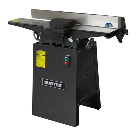
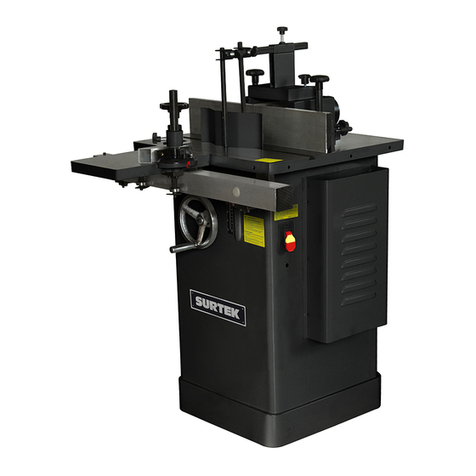
Surtek CN708 User manual

CN706A • CN708
Canteadoras
Jointers
Manual de Usuario y Garantía.
User’s Manual and Warranty.
ATENCIÓN: Lea, entienda y siga las instrucciones de seguridad contenidas en este
manual antes de operar esta herramienta.
WARNING: Read, understand and follow the safety rules in this manual, before operating this tool.
CN706A-CN708 manual.indd 1 28/05/15 14:37

2
ENGLISHESPAÑOL
General safety rules
Electric safety
Personal safety
Tool use and care
Specific safety rules for
jointers
Unpacking and assembly
Adjustments
Operation instructions
Maintenance
Technical data
Notes
Warranty policy
Normas generales de seguridad
Seguridad eléctrica
Seguridad personal
Utilización y cuidados de las
herramientas eléctricas
Advertencias de seguridad para
canteadoras
Desembalaje y ensamble
Ajustes
Instrucciones de operación
Mantenimiento
Especificaciones técnicas
Notas
Garantía
13
13
13
14
14
15
17
19
20
21
22
24
3
3
3
4
5
5
7
10
11
12
22
24
CONTENIDO CONTENT
SIMBOLOS SYMBOLS
PELIGRO, ADVERTENCIA, PRECAUCIÓN:
Indica un riesgo personal o la posibilidad
de un daño.
DANGER, CAUTION, WARNING: Indicates risk of
personal injury and/or the possibility of damage.
CN706A-CN708 manual.indd 2 28/05/15 14:37

NORMAS GENERALES DE SEGURIDAD
Esta CANTEADORA tiene características que
harán su trabajo más rápido y fácil. Seguridad,
comodidad y confiabilidad fueron previstos
como prioridad para el diseño del mismo, ha-
ciendo más fácil su operación.
ADVERTENCIA: Lea todas las advertencias
de seguridad y todas las instrucciones. La omi-
sión de alguna de las advertencias e instruccio-
nes que se enlistan a continuación puede dar
como resultado un choque eléctrico, fuego y/o
un daños serios.
CONSERVE TODAS LAS ADVERTENCIAS Y
TODAS LAS INSTRUCCIONES.
SEGURIDAD EN EL ÁREA DE TRABAJO
Mantenga el área de trabajo limpia y bien ilu-
minada. Las áreas desordenadas y oscuras pro-
vocan accidentes.
No maneje herramientas eléctricas en atmós-
feras explosivas, tales como en presencia de
líquidos inflamables, gases o polvo. Las herra-
mientas eléctricas crean chispas que pueden
encender el polvo o los humos.
Mantenga alejados a los niños y curiosos
mientras maneja una herramienta eléctrica.
Las distracciones pueden causarle la pérdida
del control.
SEGURIDAD ELÉCTRICA
La clavija de la herramienta eléctrica debe
coincidir con receptáculo. No modificar nunca
la clavija de ninguna manera. No usar ningún
adaptador de clavijas con herramientas eléctri-
cas puestas a tierra. Clavijas no modificadas y
bases coincidentes reducirán el riesgo de cho-
que eléctrico.
Evite el contacto del cuerpo con superficies
puestas a tierra como tuberías, radiadores, co-
cinas eléctricas y refrigeradores. Hay un riesgo
aumentado de choque eléctrico si su cuerpo
está puesto a tierra.
No exponga las herramientas eléctricas a la llu-
via o a condiciones de humedad. El agua que
entre en la herramienta aumentará el riesgo
de choque eléctrico.
No abuse del cable. No usar nunca el cable para
llevar, levantar o desenchufar la herramienta
eléctrica. Mantenga el cable lejos del calor,
aceite, cantos vivos o piezas en movimiento.
Los cables dañados o enredados aumentan el
riesgo de choque eléctrico.
Cuando maneje una herramienta eléctrica en
el exterior, use una prolongación de cable ade-
cuada para uso en el exterior. El uso de una
prolongación de cable adecuada para uso en el
exterior reduce el riesgo de choque eléctrico.
“ESTA HERRAMIENTA CUENTA CON UN
SUJETA CABLE TIPO “Y“, EN CASO DE DAÑAR-
SE EL CORDÓN DE ALIMENTACIÓN, ÉSTE DE-
BERÁ SER REEMPLAZADO POR EL FABRICANTE,
SUS CENTROS DE SERVICIO AUTORIZADOS, O
PERSONAL CALIFICADO A FIN DE EVITAR RIES-
GOS.”
EXTENSIONES DE CABLE
NOTA: El uso de cables dañados incrementa el
riesgo de descargas eléctricas o quemaduras.
Si es necesario un cable de extensión, debe ser
usado un cable con el tamaño adecuado de los
conductores. La tabla de la siguiente página,
muestra el tamaño correcto para usar depen-
diendo en la longitud del cable y el rango de
amperaje especificado en la etiqueta de valo-
res nominales del producto. Si está en duda,
use el rango próximo más grande.
Siempre use cables de extensión listados en UL,
CSA o NOM.
TAMAÑOS RECOMENDADOS DE EXTENSIONES
DE CABLE:
Cuando esté usando el producto afuera, use
una extensión para exteriores marcadas con lo
siguiente: “WA” o “W”. Estas extensiones están
pensadas para trabajar en exteriores y reducen
el riesgo de descarga eléctrica.
SEGURIDAD PERSONAL
Esté alerta, vigile lo que está haciendo y use el
sentido común cuando maneje una herramien-
ta eléctrica. No use una herramienta eléctrica
cuando esté cansado o bajo la influencia de
3
ESPAÑOL•Manual de Usuario
CN706A-CN708 manual.indd 3 28/05/15 14:37

drogas, alcohol o medicamentos. Un momento
de distracción mientras maneja herramientas
eléctricas puede causar un daño personal serio.
Use equipo de seguridad. Lleve siempre pro-
tección para los ojos. La utilización para las
condiciones apropiadas de un equipo de segu-
ridad tal como mascarilla antipolvo, zapatos no
resbaladizos, gorro duro, o protección para los
oídos reducirá los daños personales.
Evite un arranque accidental. Asegúrese de
que el interruptor está en posición apagado
antes de conectar a la red y/o a la batería, co-
ger o transportar la herramienta. Transportar
herramientas eléctricas con el dedo sobre el
interruptor o enchufar herramientas eléctricas
que tienen en interruptor en posición encendi-
do invita a accidentes.
Retire llaves o herramienta antes de arrancar
la herramienta eléctrica. Una llave o herra-
mienta dejada unida a una pieza rotativa de
una herramienta eléctrica puede causar un
daño personal.
No se sobrepase. Mantenga los pies bien asen-
tados sobre el suelo y conserve el equilibrio en
todo momento. Esto permite un mejor control
de la herramienta eléctrica en situaciones in-
esperadas.
Vista adecuadamente. No vista ropa suelta o
joyas. Mantenga su pelo, su ropa y guantes
alejados de las piezas en movimiento. La ropa
suelta, las joyas o el pelo largo pueden ser co-
gidos en las piezas en movimiento.
Si hay dispositivos para la conexión de medios
de extracción y recolección de polvo, asegúre-
se de que éstos estén conectados y se usen co-
rrectamente. El uso de estos dispositivos puede
reducir los peligros relacionados con el polvo.
IMPORTANTE: Este aparato no se destina
para utilizarse por personas (incluyendo niños)
cuyas capacidades físicas, sensoriales o menta-
les sean diferentes o estén reducidas, o carez-
can de experiencia o conocimiento, a menos
que dichas personas reciban una supervisión o
capacitación para el funcionamiento del apa-
rato por una persona responsable de su segu-
ridad. Los niños deben supervisarse para ase-
gurar que ellos no empleen los aparatos como
juguete.
UTILIZACIÓN Y CUIDADOS DE LAS
HERRAMIENTAS ELÉCTRICAS
No fuerce la herramienta eléctrica. Use la he-
rramienta eléctrica correcta para su aplicación.
La herramienta eléctrica correcta hará el tra-
bajo mejor y más seguro al ritmo para la que
fue concebida.
No use la herramienta eléctrica si el interrup-
tor no gira “encendido” y “apagado”. Cual-
quier herramienta eléctrica que no pueda con-
trolarse con el interruptor es peligrosa y debe
repararse.
Desenchufe la clavija de la fuente de alimen-
tación y/o de la batería antes de efectuar
cualquier ajuste, cambio de accesorios, o de
almacenar las herramientas eléctricas. Tales
medidas preventivas de seguridad reducen el
riesgo de arrancar la herramienta accidental-
mente.
Almacene las herramientas eléctricas inactivas
fuera del alcance de los niños y no permita el
manejo de la herramienta eléctrica a personas
no familiarizadas con las herramientas o con
estas instrucciones. Las herramientas eléctricas
son peligrosas en manos de usuarios no entre-
nados.
Mantenga las herramientas eléctricas. Com-
pruebe que las partes móviles no estén des-
alineadas o trabadas, que no haya piezas ro-
tas u otras condiciones que puedan afectar la
operación de las herramientas eléctricas. Las
herramientas eléctricas se reparan antes de su
uso, cuando están dañadas. Muchos acciden-
tes son causados por herramientas eléctricas
pobremente mantenidas.
Mantenga las herramientas de corte afiladas y
limpias. Las herramientas de corte mantenidas
correctamente con los bordes de corte afilados
son menos probables de trabarse y más fáciles
de controlar.
Use la herramienta eléctrica, accesorios y pun-
tas de herramienta, etc. de acuerdo con estas
instrucciones y de la manera prevista para el
tipo particular de herramienta eléctrica, te-
niendo en cuenta las condiciones de trabajo
y el trabajo a desarrollar. El uso de la herra-
mienta eléctrica para aplicaciones diferentes
de las previstas podría causar una situación de
peligro.
4
CN706A-CN708 manual.indd 4 28/05/15 14:37
SERVICIO
Haga revisar su herramienta eléctrica por un
servicio de reparación calificado usando sola-
mente piezas de reemplazo idénticas. Esto ga-
rantizará que la seguridad de la herramienta
eléctrica se mantiene.
ADVERTENCIAS DE SEGURIDAD
PARA CANTEADORAS
1. ANTES DE COMENZAR. Inspeccione cuida-
dosamente el material antes de alimentar el
cabezal de corte. Si tiene alguna duda sobre
la estabilidad o la integridad estructural de tu
material a trabajar, NO PROCEDAS AL CAN-
TEADO!
2. MANTENGA LAS RELACIONES CORRECTAS
de la superficie de abastecimiento y salida de
producto de la superficie de la mesa y la ruta
del cabezal de corte.
3. SIEMPRE USE UN BLOQUE DE EMPUJE mien-
tras esté canteando. Nunca coloque sus manos
directamente sobre el cabezal de corte.
4. SOSTENGA LA PIEZA DE TRABAJO todo el
tiempo durante la operación, mantenga el
control sobre el trabajo realizado en todo mo-
mento.
5. MIENTRAS REALICE EL CANTEADO, no per-
manezca en ninguno de los extremos de la
mesa de trabajo. Colóquese justo al lado de la
parte de alimentación para evitar el contragol-
pe.
6. NUNCA REALICE UN CANTEADO de profun-
didad mayor a 1/8".
7. NUNCA REALICE EL CANTEADO DE UNA PIE-
ZA que tenga irregularidades. Todos los defec-
tos en el material deben ser corregidos antes
de someterse al cepillado o canteado.
8. NUNCA CANTEAR madera por la testa.
9. CANTEAR MADERA POR LA TESTA. Esta ac-
ción es peligrosa y puede desprender residuos
de material (rebabas).
10. CON EXCEPCIÓN DEL REBAJADO, todas las
operaciones deben ser realizadas con la guar-
da puesta. Después del rebajado, asegúrese de
colocar la guarda nuevamente en su posición.
11. NUNCA REALICE EL TRABAJO DE REGRESO
HACIA LA MESA DE ALIMENTACIÓN DE MATERIAL.
12. LOS HÁBITOS -BUENOS o MALOS- son difíci-
les de romper. El desarrollar buenos hábitos en
su taller de trabajo y la seguridad se converti-
rán en algo natural para usted.
13. “CONTRAGOLPE” es cuando la pieza de
trabajo es arrojada de la mesa de canteado
por la fuerza del cabezal de corte. Siempre
use bloques de empuje y gafas de seguridad
para reducir la posibilidad de una lesión por
un “contragolpe”. Si no comprende que es un
contragolpe o como ocurre, NO opere esta la
máquina.
14. MANTÉNGASE ALERTA, CIERTAS MADERAS
PUEDEN PROVOCAR UNA REACCIÓN ALÉR-
GICA en personas y animales, especialmente
cuando está expuesto a partículas finas de pol-
vo del material. Asegúrese de conocer el tipo
de polvo de madera al que va a estar expuesto,
siempre use la mascarilla para respirar adecua-
damente.
DESEMBALAJE Y ENSAMBLE
DESEMBALAJE
La canteadora es enviada de fábrica en dos
cajas cuidadosamente empacadas. Si descu-
bre que la máquina está dañada después de
la entrega, comuníquese inmediatamente con
un centro de servicio autorizado para asesora-
miento.
ADVERTENCIA: Si tuviera que trasladar esta
máquina por escaleras, la máquina debe ser
desarmada y transportada en piezas. Asegúre-
se de que la estructura del piso y las escaleras
sean capaces de soportar el peso combinado
de las partes de la máquina y de quienes las
transportan.
ADVERTENCIA: La canteadora es una má-
quina pesada. NO se sobre esfuerce mientras
desempaca o la transporta, necesitará que al-
guien lo asista. Lesiones personales graves po-
drían ocurrir si estas instrucciones no son segui-
das.
LIMPIEZA
Las superficies sin pintar están recubiertas con
un aceite parafinado para protegerlas de la co-
rrosión durante el envío. Remueva esta capa
protectora con un solvente o un desengrasan-
te a base de cítricos. Evite los solventes a base
de cloro, ya que pudieran dañar las superficies
con las que entren en contacto. Siempre siga
las instrucciones de uso para la máquina que
vaya a limpiar.
5
ESPAÑOL•Manual de Usuario
CN706A-CN708 manual.indd 5 28/05/15 14:37

6
ADVERTENCIA: No use gasolina o cual-
quier otro solvente a base de petróleo. Estos
son altamente inflamables. Existe riesgo de ex-
plosión y quemaduras si estos productos son
usados. Lesiones graves pueden ocurrir si esta
advertencia es ignorada.
PRECAUCIÓN: Muchos de los solventes co-
múnmente usados para limpiar maquinaria
pueden ser tóxicos al inhalarse o ingerirse.
Siempre trabaje en áreas bien ventiladas lejos
de potenciales fuentes de ignición cuando se
utilicen solventes. Tenga cuidado cuando se
tenga residuos de trapos o cualquier tela para
estar seguro que no provoquen incendios o pe-
ligros al medio ambiente. Mantenga niños y
animales a una distancia segura cuando se lim-
pie o ensamble esta máquina
ADVERTENCIA: No fume mientras manipu-
le solventes. Existe riesgo de explosión y fuego
ya pudiera provocar lesiones graves.
CONSIDERACIONES PARA SU COLOCACIÓN
CARGA DEL PISO
Esta canteadora representa un peso de carga
moderado en un área pequeña. La mayoría de
los pisos comerciales o residenciales, deberían
de ser suficientes para cargar con el peso. Si
usted tiene duda de la resistencia del piso, de-
berá consultar con un arquitecto o un ingenie-
ro civil sobre las adecuaciones necesarias para
que su piso soporte la carga.
ESPACIOS SEGUROS Y LIBRES
Los espacios seguros y libres son las distancias
entre las máquinas y los obstáculos que permi-
tan la operación segura de cada máquina sin
tener limitaciones de movimiento. Considere
las necesidades existentes y previstas para la
máquina, tamaño del material que se maneja-
rá a través de cada máquina y espacios para re-
pisas y/o mesas auxiliares. También considere
la posición relativa de cada máquina con res-
pecto a las otras para el manejo eficiente del
material. Asegúrese de proporcionarse espacio
suficiente para operar seguramente sus máqui-
nas en cualquier operación previsible.
ILUMINACIÓN Y TOMAS DE CORRIENTE
La iluminación debe ser suficientemente clara
para eliminar sombras y prevenir esfuerzo ocu-
lar. Los circuitos eléctricos deben ser planeados
para soportar cargas combinadas de consumo
de corriente de motores. Las tomas de corrien-
te deben ser colocadas cerca de cada máqui-
na para que extensiones de cable no obstruyan
áreas transitadas.
ENSAMBLAJE
ADVERTENCIA: Toda pieza metálica troque-
lada tiene un eje filoso (llamado “flashing”)
después de ser formadas. Este es removido en
la fábrica. Aunque algunas veces un poco de
“flashing” puede escapar a la inspección. Por
favor examine los ejes de todas las partes me-
cánicas troqueladas antes de manipularlas o
una lesión grave pudiera ocurrir
ADVERTENCIAS
· Desconecte el equipo de la fuente de alimen-
tación para realizar cualquier acción de mante-
nimiento, ensamblaje o ajuste. No hacer esto
pudiera ocasionar graves lesiones personales.
· Mantenga cualquier ropa holgada sujeta y
fuera del alcance de la maquinaria y mantenga
su pelo sujetado hacia atrás.
· Use gafas de seguridad durante todo el pro-
ceso de ensamblado. El no cumplir con esto pu-
diera provocar lesiones graves.
La mayor parte de las canteadoras han sido en-
sambladas desde fábrica, pero algunas partes
deben ser ensambladas o instaladas después de
la entrega. A continuación le mostraremos el
proceso de ensamblaje paso a paso. Por favor
siga el orden presentado aquí a lo largo de
todo el proceso.
ENSAMBLE DE LA CANTEADORA A LA BASE
En este paso pudiera recurrir de la asistencia de
al menos dos personas.
Para posicionar la canteadora en su lugar:
1. Levante la unidad principal y colóquela en la
base, asegurándose de posicionar la polea del
cabezal de corte sobre la ranura de la parte su-
perior del soporte.
2. Alinee cuidadosamente los orificios de mon-
taje de la base con los orificios roscados en la
base de la canteadora. Asegure la canteadora a
la base usando los tres pernos especiales M10 y
las arandelas planas de 10 mm que se proveen.
Asegúrese de no ejercer una presión excesiva.
CN706A-CN708 manual.indd 6 28/05/15 14:37

7
ADVERTENCIA: La unidad principal de la
canteadora es muy pesada. Se requerirá de al
menos dos personas cuando levante y coloque
en la superficie de la base. Se podrían sufrir le-
siones graves si los métodos de seguridad des-
critos para su colocación no son seguidos.
BANDA 'V'
1. Afloje los pernos
del motor hasta que
pueda ensamblar
Banda en V a las po-
leas. Vea la figura 1
(La otra se encuentra
en el conducto de de-
sechos).
2. Alinee las poleas del motor y del cabezal de
corte una con otra usando una plomada o una
regla. Mueva el motor hasta que la cara de la
polea del motor este alineada con la polea del
cabezal de corte y asegure el motor apretando
los pernos (Vea la figura 2).
GUÍA
Coloque el cuerpo
de la guía al soporte,
asegurándose que se
ajuste sobre la llave.
Inserte el tornillo de
seguridad y enrósque-
lo en la tuerca especial
proporcionada (Fig.3).
El borde de la tuerca especial debe sobresalir
hacia arriba cuando esta correctamente insta-
lado.
ADVERTENCIA: NO deslice la guía a través
de la mesa de salida o se provocaran ralladuras.
GUARDA DEL CABEZAL DE CORTE
1. El orificio del eje de la guarda del cabezal,
esta ranurado en un extremo.
Esta ranura embona
con el extremo al final
del resorte localizado
en la caja de este (Ver fi-
gura 4). Bloquee el ori-
ficio del eje para locali-
zar donde se encuentra
este extremo.
2. Remueva el tornillo de fijación del extremo
ranurado del eje del pivote. Rote la caja del re-
sorte en sentido anti-horario, aproximadamen-
te una vuelta. Inserte el eje de la guarda den-
tro el orificio del eje del pivote, alineando la
ranura con su extremo.
3. El eje de la guarda del cabezal debe embo-
nar hasta el fondo del orificio del pivote cuan-
do esté correctamente embonado al extremo
del resorte y debe sujetar la guarda contra la
guía.
4. La guarda de la cortadora debe permanecer
firme contra la guía, cubra completamente el
cabezal de corte y regréselo a su posición cuan-
do se libere. Si no se ha conseguido esto, repita
los pasos 2 y 3, incrementando el número de
vueltas a la caja del resorte a 1-1/2. Vuelva a in-
sertar el tornillo de fijación dentro del extremo
del eje pivote.
PROTECTOR DE LA BANDA
Utilice dos tuercas hexagonales para instalar el
protector de la polea a la base de la carcasa. No
apriete excesivamente.
ADVERTENCIA: NO realice ningún paso de
ensamblado, ajustes, o mantenimiento mien-
tras la canteadora esté en funcionamiento.
Asegúrese de que esté apagada, desconectada
de la fuente de alimentación y las partes mo-
vibles de la máquina se han detenido por com-
pleto antes de realizar cualquier ajuste. El no
cumplir con las indicaciones anteriores podría
provocar lesiones graves personales.
AJUSTES
SUJETADORES DE LA MESA
ADVERTENCIA: Siempre bloquee la mesa
con el seguro antes de usar la canteadora. El
hacer caso omiso de esta advertencia, podría
provocar que la mesa se deslice hacia abajo
mientras la canteadora está en operación. Le-
siones personales graves podrían ocurrir.
Tornillos
Chumacera
Tornillos
Polea del
cabezal
Cabezal
Polea del
motor
Sujetadores
Fig.1
Fig.2
Fig.4
ESPAÑOL•Manual de Usuario
Llave
Tornillo
de seguridad
Fig.3
CN706A-CN708 manual.indd 7 28/05/15 14:37

8
La función de los sujetadores (Fig. 3) es permi-
tir el ajuste preciso al movimiento de la mesa a
lo largo de los rieles. El ajuste de los sujetado-
res dictaminará cuán fácil será deslizar la mesa
hacia arriba y hacia abajo con las manivelas.
Para ajustar los sujetadores:
1. Desenrosque con
varias vueltas las tuer-
cas de arriba y de
abajo de la mesa de
alimentación, dejan-
do la manija de segu-
ridad apretada. Vea la
figura 5.
2. Afloje la manija de seguridad de la mesa y
ajuste los tornillos de fijación de arriba y abajo
del sujetador hasta que el movimiento de la
mesa sea suave y controlado.
3. Una vez que el sujetador ha sido propia-
mente ajustado, apriete las tuercas y repita los
pasos 1 y 2 para la mesa de salida.
4. Asegúrese que no hay un movimiento de
lado a lado por parte de las mesas un vez que
las tuercas han sido apretadas. Si lo hay, repita
los pasos 1-4.
CUCHILLAS
ADVERTENCIA: Estas cuchillas son extre-
madamente filosas. Nunca sujete el cabezal de
corte directamente para rotarlo. Siempre utili-
ce la polea para girarlo. Asegúrese de que la
canteadora este desconectada de la fuente de
alimentación antes de realizar cualquier ajuste.
Lesiones personales graves se podrían provocar
de no cumplir con lo antes mencionado.
INSPECCIÓN DE LAS CUCHILLAS
NOTA: Las cuchillas de la canteadora deben ser
remplazadas o ajustadas periódicamente.
Los ajustes deben ser tan precisos como sea po-
sible con un margen de tolerancia de .002"a
.003" para prolongar el filo de los bordes de la
cuchilla. Un mal ajuste de las cuchillas podría
provocar un desbalance del cabezal de corte
y acortar la vida de los rodamientos, así como
provocar un canteado deficiente o resultados
no deseados. Las cuchillas son ajustadas desde
fábrica usando tornillos de fijación o resortes,
antes de ser enviadas. Ahora es un buen mo-
mento para volver a verificar los ajustes de las
cuchillas.
Para inspeccionar y ajustar las cuchillas:
1. ¡Desconecte la canteadora!
2. Quite la cubierta superior o la guarda del ca-
bezal de corte para descubrir la parte superior.
3. Cuidadosamente de vuelta a el cabezal de
corte (usando la polea) hasta que la primera
cuchilla se encuentre en un punto muerto al
centro.
4. Con ayuda de un
calibrador de ajuste
de la cuchilla, verifi-
que su altura. La plan-
tilla debe apoyarse só-
lidamente con ambas
patas sobre el cabezal
de corte (Figura 6).
Si la cuchilla es ajustada apropiadamente; el
punto de contacto en el centro de cada ajus-
tador debe tocar solamente la punta de la cu-
chilla. Si la cuchilla no hace contacto, o si la
cuchilla hace que las patas del ajustador no se
sienten sobre el cabezal de corte, las cuchillas
necesitarán ser ajustadas.
PRECAUCIÓN: Recuerde, las cuchillas de
la canteadora son extremadamente filosas.
Tenga especial cuidado cuando las manipule
durante la instalación o su desmantelamiento.
AJUSTANDO CON LOS TORNILLOS DE FIJACIÓN
Cuando utilice tornillos de fijación, no es ne-
cesario instalar los resortes. Las cuchillas están
fijas en el cabezal de corte con chavetas tipo
cuña y pernos de chaveta. Los tornillos de fija-
ción bajo las cuchillas permiten un ajuste fino
que ayuda en el proceso de fijación. Para ali-
near nuevamente las cuchillas:
1. ¡Desconecte la canteadora!
2. Afloje los pernos tipo chaveta hasta que la
cuchilla este suelta en la ranura. Los pernos
tipo chaveta giran en sentido horario para
aflojar y en sentido anti-horario para apretar
(cuando se está frente a la cabeza de la tuerca).
Ver figura 7 y 7b.
Calibrador
de ajuste de
la cuchilla
Tornillos de
fijación
Resortes
Fig.6
Tornillos
Manija de
seguridad
Tuercas de
seguridad Fig.5
Cuchilla
Tornillo
ajustador
Ajustador
Tornillo de
fijación
Fig.7
Cuchilla
Tornillo
ajustador Ajustador
Fig.7b
CN706A-CN708 manual.indd 8 28/05/15 14:37

9
3. Coloque el calibrador de ajuste de la cuchi-
lla sobre el cabezal de corte como se describió
anteriormente, asegurándose que las patas del
medidor estén colocadas sobre el cabezal de
corte de manera adecuada y segura.
4. Ajuste los tornillos inferiores de cada extre-
mo de la cuchilla hasta que ambas patas del
medidor descansen uniformemente en el cabe-
zal de corte y la cuchilla solo toque el fondo
de la pata central del medidor. El calibrador de
ajuste hará que las cuchillas sobresalgan a una
distancia uniforme de aproximadamente .070”
sobre el cabezal de corte. La altura de las cu-
chillas no debe variar más allá de .002"-.003" a
todo lo largo del cabezal de corte.
5. Mantenga una presión constante sobre el ca-
librador de ajuste mientras vuelva a apretar los
pernos de chaveta
6. Repita el mismo procedimiento para las cu-
chillas restantes. Como se mencionó anterior-
mente, el calibrador de ajuste estándar es sa-
tisfactorio para tareas de precisión razonable
para ajuste de cuchillas.
AJUSTES USANDO LOS RESORTES
Las cuchillas están aseguradas dentro del cabe-
zal de corte con chavetas tipo cuña y pernos
de chaveta.
1. ¡Desconecte la canteadora!
2. Afloje los pernos
de chaveta hasta que
la cuchilla este suelta
en la ranura. Los per-
nos de chaveta giran
en sentido horario
para aflojar y en sen-
tido anti horario para
apretar (Cuando se
está frente a la cabe-
za de la tuerca). Vea
figura 7a y 7b.
3. Coloque el medidor de ajuste de la cuchilla
como se describió anteriormente, para que sus
patas reposen de manera segura en el cabezal
de corte. Asegúrese de que la varilla del me-
didor esté paralela a el cabezal de corte para
mantener una buena precisión.
4. La presión de descenso que provoca el me-
didor hará que las cuchillas sobresalgan a una
distancia uniforme de aproximadamente .070”
sobre el cabezal de corte. La altura de las cu-
chillas no deberá variar más allá de .002"-.003"
a todo lo largo del cabezal de corte.
5. Mantenga una presión constante en el me-
didor de ajuste mientras vuelva a apretar los
pernos de chaveta.
6. Repita el mismo procedimiento para las cu-
chillas restantes. Como se mencionó anterior-
mente, el medidor de ajuste estándar es sa-
tisfactorio para tareas de precisión razonable
para ajuste de cuchillas.
GUÍA A 90°
1. Coloque una escua-
dra en la mesa de sa-
lida bastante cerca del
cabezal de corte. Vea
la figura 8.
2. Afloje el mango de bloqueo de la guía y
la tuerca del perno de tope positivo. Gire el
perno de tope contra el resguardo hasta que la
guía haga contacto con el borde de la escua-
dra uniformemente.
3. Apriete las tuercas
del perno de tope e
incline la guía hacia
adelante, luego para
atrás hacia el tope.
Vea la figura 9.
4. Vuelva a revisar con la escuadra. Apretar las
tuercas hará que el perno de tope se mueva un
poco, así que se necesitará de algo de prueba y
error para perfeccionar el ajuste.
GUÍA TOPE 45°
La guía puede ser inclinada a 45° aflojando el
mango de bloqueo, levantando el tope de res-
guardo de 90°, y moviendo la guía en la posi-
ción deseada.
Para poner el tope de
resguardo de 45°:
1. Afloje la tuerca y
baje la guía hasta que
sienta la manija de
bloqueo (Fig.10).
2. Usando una escuadra establezca la guía a
45°, coloque el talón de la escuadra en la mesa
de salida y la hoja contra la cara de la guía.
3. Si hay una diferencia entre la hoja de la es-
cuadra y la cara de la guía, gire el perno de
tope hasta que desaparezca la diferencia.
Cuchilla
Tornillo
ajustador
Ajustador
Resorte
Fig.7a
Fig.8
Tope
positivo
Fig.9
Tuerca
tope
Tope de
resguardo
Fig.10
ESPAÑOL•Manual de Usuario
CN706A-CN708 manual.indd 9 28/05/15 14:37

10
4. Apriete la con-
tratuerca. Mueva su
guía hacia adelante,
luego de vuelta hacia
el tope. Vuelva a che-
car el perno de tope
(Fig.10a).
ADVERTENCIA: Las cuchillas de la cantea-
dora están peligrosamente afiladas. Tenga ex-
trema precaución cuando manipule cuchillas o
trabaje cerca de ellas.
Después de terminar, apriete todas las tuercas
que hayan sido instaladas, entonces instale la
cubierta del colector de polvo.
INSTRUCCIONES DE OPERACIÓN
Las siguientes instrucciones le darán al princi-
piante una introducción a la operación de can-
teado. Use material de desperdicio para probar
ajustes y para “sentir” las operaciones antes de
intentar un trabajo normal.
IMPORTANTE: USE SIEMPRE LA GUARDA Y
MANTENGA LAS MANOS LEJOS DEL CABEZAL
DE CORTE.
COLOCACIÓN DE LAS MANOS DURANTE LA
ALIMENTACIÓN
Al inicio del corte, con la mano izquierda sujete
la pieza firmemente contra la mesa frontal y
la barrera guía, mientras que la mano derecha
empuja la pieza hacia las cuchillas. Después de
iniciar el corte, la superficie nueva descansa
firmemente sobre la mesa posterior como se
muestra en la figura 11.
La mano derecha empuja la pieza hacia delan-
te y antes de que la mano derecha alcance el
cabezal de corte, se debe mover a la pieza en
la mesa posterior. NUNCA PASE LAS MANOS
DIRECTAMENTE SOBRE EL CABEZAL DE CORTE.
CANTEADO DE UN BORDE
Esta es la operación más común para la cantea-
dora. Ajuste la barrera guía en escuadra con
la mesa. La profundidad de corte debe ser la
mínima requerida para obtener un borde rec-
to. Sujete la mejor cara de la pieza firmemente
contra la barrera guía durante toda la alimen-
tación.
CANTEADO DE PIEZAS ARQUEADAS
Si la madera que se va a cantear esta pandeada
o curva, haga cortes ligeros hasta que la super-
ficie esté plana. Evite forzar el material hacia
abajo contra la mesa; una presión excesiva va
a regresar como resorte después de pasar las
cuchillas y permanecerá curva.
CANTEADO DE PIEZAS CORTAS O DELGADAS
Cuando cantee piezas cortas o delgadas, use
un palo de empuje para eliminar todo riesgo
para las manos.
Se muestran dos
tipos en la figura
12. Se hacen fá-
cilmente con ma-
terial de desper-
dicio.
DIRECCIÓN DE LA VETA
Evite alimentar piezas a la canteadora en con-
tra de la veta como se muestra en la figura 13.
El resultado será astillado.
Alimente como la veta como en la figura 14
para obtener una superficie suave.
BISELADO
Para cortar un bisel, fije la barrera guía al án-
gulo deseado y corra la pieza por las cuchillas
mientras la sujeta firmemente contra la barre-
ra guía y las mesas. Se pueden requerir varias
pasadas para alcanzar el resultado deseado.
Cuando el ángulo es pequeño, existe una pe-
queña diferencia si la barrera guía se inclina a
la derecha o izquierda. Sin embargo, en ángu-
los grandes que se acerquen a los 45º, es cada
vez más difícil sujetar la pieza adecuadamen-
te cuando la barrera guía esté inclinada a la
derecha. La ventaja de que la barrera guía se
incline a ambos lados se aprecia bajo estas con-
diciones.
Navajas
Mesa
trasera
MADERA
Mesa frontal
Fig.11
Fig.12
Fig.13 Fig.14
Fig.10a
CN706A-CN708 manual.indd 10 28/05/15 14:37

11
Cuando se inclina a la izquierda, la barrera guía
forma una V con las mesas y la pieza se puede
pasar fácilmente dentro de la bolsa mientras
pasa por las cuchillas. Si el bisel se realiza sobre
la pieza en una dirección tal que conlleve cor-
tar contra la veta. Será mejor inclinar la mesa
a la derecha.
CORTE DE DISMINUCIONES
Una de las operaciones más útiles de la cantea-
dora es cortar un borde con disminución. Este
método se puede usar en una amplia variedad
de trabajos. Disminución de Patas de algún
mueble son un ejemplo común.
En lugar de colocar la pieza sobre la mesa
frontal, coloque el extremo frontal de la pieza
sobre la mesa posterior. Haga esto con mucho
cuidado, ya que la pieza tocará las cuchillas y
éstas “morderán” la pieza con una tendencia
a rechazarla a menos que la pieza esté firme-
mente sujeta. Ahora empuje la pieza hacia de-
lante como en un canteado normal. El efecto
es cepillar la madera enfrente de las cuchillas,
para aumentar la profundidad, dejando una
superficie disminuida.
La cresta dejada por las cuchillas cuando se
inició la disminución se puede eliminar hacien-
do un corte muy ligero con el método normal
de canteado, con la mesa frontal elevada a su
posición normal. Se requiere práctica en esta
operación, y se aconseja al principiante hacer
cortes de prueba con material de desperdicio.
Corte de disminuciones en parte de la longitud
y un número de otras operaciones especiales
pueden ser realizadas fácilmente por artesanos
con experiencia.
MANTENIMIENTO
MANTENIMIENTO Y REPARACIONES DEL
CABEZAL DE CORTE
Después de un uso considerable, las cuchillas
pierden filo y no será posible hacer trabajos
exactos. A menos que estén muy dañadas por
pasar metal u otro material duro, se pueden
afilar como se indica a continuación:
AFILADO DE CUCHILLAS
1. DESCONECTE LA MAQUINA DE LA CORRIEN-
TE ELÉCTRICA.
2. Use una piedra fina de carburo, cúbrala par-
cialmente con papel como se indica en la figura
15 para evitar hacer marcas en la mesa.
3. Coloque la piedra sobre la mesa frontal, baje
la mesa y gire el cabezal de corte hasta que la
piedra descanse plana sobre el bisel de la cuchi-
lla como se muestra.
4. Sujete el cabezal de corte para que no gire y
afile el borde biselado de la cuchilla deslizando
la piedra a lo largo de la cuchilla hacia delante
y hacia atrás cruzando la mesa.
5. Haga la misma cantidad de afilado en cada
una de las tres cuchillas.
CUIDADO DE LAS CUCHILLAS
La goma y la savia que se adhieren a las cuchi-
llas causan una fricción excesiva mientras conti-
núa el trabajo, resultando en un sobre calenta-
miento de las cuchillas, cortes menos eficientes
y consecuentemente pérdida de la cuchilla. Use
un removedor de goma y óxido para limpiar
las cuchillas.
Cuando estas cuchillas pierdan el filo lo sufi-
ciente para notarlo cuando se corta, deben ser
reafiladas. Una cuchilla afilada trabaja más fá-
cil y resulta en una vida más larga de la misma.
El precio por una cuchilla sin filo es una vida
menor de la misma, un desgaste mayor y des-
garres en todas las partes de la máquina.
Con el tiempo, puede aparecer óxido sobre
la mesa, la barrera guía y otras partes de la
canteadora, resultando en menor eficiencia
y exactitud de la máquina. Use cera en pasta
que se pueda aplicar para evitar la formación
de óxido, sin embargo, si el óxido se ha for-
mado ya en estas partes, use un removedor de
óxido para recuperar la exactitud original de
la máquina.
LUBRICACIÓN
Recomendamos usar grasa ligera de buen gra-
do en los tornillos de ajuste de acero para los
mecanismos de elevación de las mesas frontal y
trasera. Aplique ocasionalmente unas cuantas
gotas de aceite para máquina ligero a las cha-
PIEDRA DE LIJADO
CUBIERTO PARCIALMENTE
CON PAPEL
Navajas
Mesa
trasera
Mesa frontal
Fig.15
ESPAÑOL•Manual de Usuario
CN706A-CN708 manual.indd 11 28/05/15 14:37

12
vetas en el costado derecho de cada mesa para
que se deslicen libremente en relación con la
carcasa de la base. El cabezal de corte corre en
2 baleros de una línea sellados y cubiertos, que
son pre-lubricados para toda su vida.
REPARACIÓN DEL CABEZAL DE CORTE
Cuando las cuchillas de el cabezal de corte
no pueden ser afiladas apropiadamente para
producir un cepillado liso, limpie el cabezal de
corte de acuerdo a los métodos descritos ante-
riormente. Cuando los baleros de el cabezal de
corte necesiten ser reemplazados, quite com-
pletamente el cabezal de corte incluyendo los
baleros y la carcasa trasera, quitando el tornillo
de la base de cada envolvente de balero.
Sugerimos al usuario comprar un cabezal de
corte adicional con baleros y envolventes. Lo
cual es necesario para mantener la máquina
en operación cuando el original se envíe a re-
paración, por ejemplo reemplazo de baleros,
afilado de cuchillas etc.
El costo adicional de una cabeza de corte se
justifica cuando se requiere una máxima pro-
ducción y alta calidad.
Cuando el montaje de el cabezal de corte se ha
realizado, asegúrese de que los asientos curva-
dos de la maquina de la base estén limpios de
polvo, suciedad o grasa para obtener un buen
ensamble.
ESPECIFICACIONES TÉCNICAS
VOLTAJE - FRECUENCIA
MESA DE TRABAJO
CAPACIDAD DE CORTE
RANURACIÓN
VELOCIDAD EN VACÍO
CORTES POR MINUTO
POTENCIA
PESO
120 V ~ 60 Hz
1 215 mm x 184 mm
6" x 1/8" (152 mm x 3,1 mm)
1/2" (12,7 mm)
5 200 r/min
15 600
750 W (1 HP)
102 kg (225 lb)
VOLTAJE - FRECUENCIA
MESA DE TRABAJO
CAPACIDAD DE CORTE
RANURACIÓN
VELOCIDAD EN VACÍO
CORTES POR MINUTO
POTENCIA
PESO
120 V ~ / 220 V ~ 60 Hz
1 215 mm x 184 mm
8" x 1/8" (200 mm x 3,1 mm)
3/8" (10 mm)
5 200 r/min
15 600
1 500 W (2 HP)
132 kg (291 lb)
CN706A
CN708
CN706A-CN708 manual.indd 12 28/05/15 14:37

GENERAL SAFETY RULES
Your JOINTER has many features that will make
your job faster and easier. Safety, performance
and reliability have been given top priority in
the design of this tool, qualities to make easy
to maintain and to operate.
WARNING: Read and understand all in-
structions. Failure to follow all indications list-
ed below, may result in electric shock, fire and/
or serious personal injury.
SAVE THESE INSTRUCTIONS.
SAFETY IN WORKING AREA
Keep your work area clean and well lit. Clut-
tered benches and dark areas may cause acci-
dents.
Do not operate power tools in explosive atmo-
spheres, such as in the presence of flammable
liquids, gases or dust. Some power tools create
sparks which may provoke fire.
Keep away observers, children and visitors
while operating a power tool. Distractions can
cause you to lose control.
ELECTRIC SAFETY
Double insulation eliminates the need for the
three wire grounded power cord and ground-
ed power supply system.
Avoid the body contact with grounded surfac-
es such as pipes, radiators and refrigerators.
There is an increased risk of electric shock if
your body is grounded.
Don’t expose power tools to rain or wet condi-
tions. The presence of water into power tools
will increase the risk of electric shock.
Do not abuse of the power cord. Never use the
power cord to carry the tool and do not pull
the plug off the outlet. Keep the cable away of
heat, oil, sharp edges or moving parts. Replace
damaged cords immediately. Damaged cords
increase the risk of electric shock.
When operating a power tool outside, use an
outdoor extension cord marked “W-A” or “W”.
These cords are rated for outdoor use and re-
duce the risk of electric shock.
EXTENSION CORDS
Replace damaged cords immediately. The use
of damaged cords can shock, burn or electric
shock. If an extension cord is necessary, a cord
with adequate size conductors should be used
to prevent excessive voltage drop, loss of pow-
er or overheating. The table below shows the
correct size to use, depending on cord length
and nameplate amperage rating of tools. In
case of doubt use the next heavier gauge. Al-
ways use UL listed extension cords.
SIZE RECOMMEND EXTENSION CABLES
PERSONAL SAFETY
Stay alert, watch what you are doing and use
common sense when operating a power tool.
Don't use the tool if you are tired or under the
influence of drugs, alcohol or medication. A
moment of inattention while operating power
tools may cause a serious personal injury.
Dress properly. Do not wear loose clothing
or jewelry. Contain long hair. Keep your hair,
clothing and gloves away of moving parts.
Loose clothes, jewelry or long hair can be
caught in moving parts.
Avoid an accidental starting. Be sure that the
switch is OFF before plugging in. Carrying
tools with the finger on the switch or plug in
the tool switch in ON may cause accidents.
Remove the adjusting keys or wrenches be-
fore turning the tool on. A wrench or a key
that is left close to a rotating part of the tool
may provoke a personal injury.
Do not overreach. Keep proper footing and
balance at all times. Proper footing and bal-
ance enables better control of the tools on un-
expected situations.
Use safety equipment. Always wear eye pro-
tection. Dust mask, nonskid safety shoes, hard
hat, or hearing protection must be used for ap-
propriate conditions.
Before connecting the tool to a power source
(receptacle, outlet, etc.) be sure that the volt-
age supplied is the same as that one specified
on the nameplate of the tool. To use a not
ENGLISH•User's manual
13
CN706A-CN708 manual.indd 13 28/05/15 14:37

specified voltage may cause a serious injury to
the user as well as damage the tool.
IMPORTANT: This appliance is not intended
for use by persons (including children) with re-
duced physical, sensory or mental capabilities
may be different or reduced, or lack of experi-
ence or knowledge, unless such persons are su-
pervised or trained to operate the product by
a person responsible for their safety. Children
should be supervised to ensure they do not use
the devices as toys.
TOOL USE AND CARE
Do not force the power tool. Use the correct
tool for the application. The correct tool will
do the job better and more safely at the rate
that it was designed to work at.
Do not use tools if switch does not turn it on
or off. Any tool that cannot be controlled with
the switch is dangerous and must be repaired.
Disconnect the plug from the power source
before making any adjustments, changing ac-
cessories or storing the tool. This preventive
safety measures reduce the risk of accidental
starting of the tool.
When the power tool is not in use, store it out
of the reach of children, and do not allow in-
dividuals who are not familiar with the power
tool or these instructions to operate it. Power
tools are dangerous in the hands on untrained
users.
Maintain the power tool. Check for misalign-
ment or binding of moving parts, broken parts,
and any other condition that may affect the
operation of the power tool. If it is damaged,
have it repaired before using. Many accidents
are caused by poorly maintained power tools.
Check for misalignment or bonding of moving
parts, breakage parts, and any other condition
that may affect the tools operation. If you find
a damaged tool, take it to service before use it.
Use only accessories that are recommended by
the manufacturer of your model. Suitable ac-
cessories for one tool, may become hazardous
when are used on another tool.
Keep cutting tools, sharpened and clean. Cut-
ting tools in good condition with sharpened
edges, are less likely to stuck in workpieces or
easier to control.
Is recommendable to use a safety device suit-
able, such a thermal and differential switch
when you are using an electric equipment.
SERVICE
Tool service must be performed only by quali-
fied repair personnel. Service or maintenance
performed by unqualified personnel could re-
sult in a risk of injury.
SPECIFIC SAFETY RULES FOR
JOINTERS
1. BEFORE STARTING OPERATIONS. With your
lumber, inspect your stock carefully before you
feed it over the cutter head. If you have any
doubts about the stability or structural integ-
rity of your stock, DO NOT JOINT IT!
2. MAINTAIN proper relationships of infeed
and outfeed table surfaces and cutterhead
knife path.
3. ALWAYS USE A PUSH BLOCK when jointing.
Never place your hands directly over the cut-
terhead.
4. SUPPORT THE WORKPIECE adequately all
times during operation, maintain control over
the work at all times.
5. WHEN JOINTING, do not stand directly at
the end of either table. Position yourself just
to the side of the infeed table to avoid possible
kickbacks.
6. NEVER MAKE JOINTING CUTS deeper than
1/8".
7. NEVER JOINT A BOARD that has loose knots.
All defects should be cut out of the board be-
fore it is planed or jointed.
8. NEVER JOINT end grain.
9. JOINT WITH THE GRAIN. Jointing against the
grain is dangerous and could produce chatter
or excessive chip out.
10. WITH THE EXCEPTION OF RABBETING, all
operations must be performed with the guard
in place. After rabbeting, be sure to replace
the guard.
11. NEVER BACK THE WORK toward the infeed
table.
12. HABITS-GOOD AND BAD-are hard to break.
Develop good habits in your shop and safety
will become second-nature to you.
13. “KICKBACK” is when the workpiece is
thrown off the jointer table by the force of the
14
CN706A-CN708 manual.indd 14 28/05/15 14:37

cutterheads. Always use push blocks and safety
glasses to reduce the likelihood of injury from
“kickback.” If you do not understand what
kickback is, or how it occurs, Do Not operate
this machine.
14. BE AWARE THAT CERTAIN WOODS MAY
CAUSE AN ALLERGIC REACTION in people and
animals, especially when exposed to fine dust.
Make sure you know what type of wood dust
you will be exposed to and always wear an ap-
proved respirator.
UNPACKING AND ASSEMBLY
UNPACKING
The jointer is shipped from the manufacturer
in two carefully packed cartons. If you discover
the machine is damaged after you've signed
for delivery, immediately call Customer Service
for advice. When you are completely satis-
fied with the condition of your shipment, you
should inventory its parts.
WARNING: If moving this machine up or
down stairs, the machine must be dismantled
and moved in smaller pieces. Make sure floor
and stair structures are capable of supporting
the combined weight of the machine parts and
the people moving them.
WARNING: The jointer is a heavy machine.
DO NOT over-exert yourself while unpacking
or moving your machine, you will need assis-
tance. Serious personal injury may occur if safe
moving methods are not followed.
CLEAN UP
The unpainted surfaces are coated with a waxy
oil to protect it from corrosion during ship-
ment. Remove this protective coating with
a solvent cleaner or citrus-based de greaser.
Avoid chlorine-based solvents as they may
damage painted surfaces should they come in
contact. Always follow the usage instructions
on the product you choose for clean up.
WARNING: Do not use gasoline or other
petroleum-based solvents. They have low flash
points, which make them extremely flam-
mable. A risk of explosion and burning exists
if these products are used. Serious personal
injury may occur if this warning is ignored.
15
ENGLISH•User's manual
CAUTION: Many of the solvents commonly
used to clean machinery can be toxic when
inhaled or ingested. Always work in well-venti-
lated areas far from potential ignition sources
when dealing with solvents. Use care when
disposing of waste rags and towels to be sure
they do not create fire or environmental haz-
ards. Keep children and animals safely away
when cleaning and assembling this machine.
WARNING: Do not smoke while using sol-
vents. A risk of explosion or fire exists and may
be the result serious personal injury may occur.
SITE CONSIDERATIONS
FLOOR LOAD
This jointer represents a moderate weight load
in a small footprint. Most commercial or home
shop floors should be sufficient to carry the
weight. If you question the strength of your
floor, you may wish to check with an ar-
chitect or structural engineer in your area to
make certain it can handle the load.
WORKING CLEARANCES
Working clearances can be thought of as the
distances between machines and obstacles that
allow safe operation of every machine without
limitation. Consider existing and anticipated
machine needs, size of material to be processed
through each machine, and space for auxiliary
stands and/or work tables. Also consider the
relative position of each machine to one an-
other for efficient material handling. Be sure
to allow yourself sufficient room to safely run
your machines in any foreseeable operation.
LIGHTING AND OUTLETS
Lighting should be bright enough to eliminate
shadow and prevent eye strain. Electrical cir-
cuits should be dedicated or large enough to
handle combined motor amp loads. Outlets
should be located near each machine so power
or extension cords are not obstructing high-
traffic areas. Be sure to observe local electrical
codes for proper installation of new lighting,
outlets, or circuits.
WARNING: All die-cut metal parts have a
sharp edge (called “flashing”) on them after
they are formed. This is removed at the factory.
Sometimes, though, a bit of flashing might es-
CN706A-CN708 manual.indd 15 28/05/15 14:37

16
cape inspection. Please examine the edges of
all die-cut metal parts before handling them or
serious injury may occur.
WARNINGS
· Disconnect from power source when perform-
ing any maintenance, assembly or adjustment.
Failure to do this may result in serious personal
injury.
· Keep loose clothing rolled up and out of the
way of machinery and keep hair pulled back.
· Wear safety glasses during the entire assem-
bly process. Failure to comply may result in seri-
ous personal injury.
Most of this Jointer has been assembled at
the factory, but some parts must be assembled
or installed after delivery. We have organized
the assembly process into steps. Please follow
along in the order presented here.
ASSEMBLING JOINTER TO STAND
This step will require at least two people.
To mount the jointer to the stand:
1. Lift the main unit onto the stand, making
sure to position the cutterhead pulley over the
slot in the top of the stand.
2. Carefully align the mounting holes in the
stand with the threaded holes in the base of
the jointer. Secure the jointer to the stand us-
ing the three M10 special bolts and 10mm flat
washers provided. Be sure not to over tighten
WARNING: The jointer main unit is very
heavy, you will need assistance when lifting it
onto the stand. Serious personal injury may oc-
cur if safe moving methods are not followed.
V-BELT
1. Loosen the motor
adjusting bolts until
you can attach the V-
Belt to the pulleys. See
Figure 1 (another is on
dust chute).
2. Align the motor and cutterhead pulleys
with each other using a plumb bob or straight-
edge. Move the motor until the face of the
motor pulley is aligned with the cutterhead
pulley and tighten the motor adjusting bolts
(See figure 2).
FENCE
Place the fence body
on the fence support,
making sure that it
fits over the key. Insert
the locking screw and
thread on the special
nut provided (fig.3).
The flange on the special nut should protrude
upward when installed correctly.
WARNING: DO NOT slide the fence across
the outfeed table. Scratching will result.
CUTTER GUARD
1. The cutterhead
guard pivot shaft is
slotted on the end.
This slot fits over the
tang at the end of a
spring located in the
spring housing.
See Figure 4. Lock down the pivot hole to get
an idea where this tang is located.
2. Remove the setscrew from the slotted end
of the pivot shaft. Rotate the spring housing
counter-clockwise, approximately 1 turn. Insert
the guard shaft into the pivot hole, lining up
the slot with the tang.
3. The cutterhead guard shaft should fit all
the way inside the pivot hole when properly
engaged with the spring tang and should hold
the guard against the fence.
4. The cutterhead guard should be held firmly
against the fence, completely cover the cut-
terhead, and move back into position when
released. If this has not been achieved, repeat
Steps 2-3, increasing the number of turns on
the spring housing to 1-1/2. Re-install the set-
screw into the end of the pivot shaft.
Set screws
Bearing
block
Set screws
Cutterhead
pulley
Cutterhead
Motor
pulley
Fig.2
Gibs
Fig.4
Fig.1
Llave
Tornillo
de seguridad
Fig.3
CN706A-CN708 manual.indd 16 28/05/15 14:37

BELT GUARD
Use two M8*12 hex bolt install the belt guard
to the jointer base casting. Do not over tighten.
WARNING: DO NOT attempt any step of
assembly, adjustments, or maintenance while
your jointer is running. Ensure that the witch
is off, power is disconnected and moving parts
have stopped before making adjustments. Fail-
ure to comply may result in serious personal
injury.
ADJUSTMENTS
TABLE GIBS
WARNING: Always lock the table with the
table lock before using the jointer. If this step is
not observed, the table could slide down while
the jointer is operating. Serious personal injury
may occur.
The function of the gibs is to allow precise
adjustment of the table movement along the
dovetail ways. Adjustment of the gib will dic-
tate how easy it will be to move the tables up
and down with the hand wheels.
To adjust gibs:
1. Unscrew the upper
and lower check nuts
on the infeed table
several turns, leaving
the lock handle tight.
See Figure 5.
2. Loosen the table lock handle and adjust
the upper and lower gib setscrews until table
movement is smooth and controlled.
3. Once the gib has been properly adjusted,
tighten check nuts and repeat Steps 1-2 for the
outfeed table.
4. Make sure there is no side-to-side movement
of the tables once the check nuts have been
tightened. If there is, repeat Steps 1-4.
KNIVES
WARNING: These knives are extremely
sharp. Never grab the cutterhead directly to ro-
tate it. Always use the drive pulley. Always be
sure the jointer is disconnected from its power
source before you make any adjustments. Seri-
ous personal injury may occur.
KNIFE INSPECTION
The knives of your jointer must be periodically
replaced or adjusted. Adjustments should be
as precise as possible with tolerances within
.002"-.003" to prolong the sharpness of the
knife-edges. Improperly adjusted knives can
unbalance the cutterhead and shorten bearing
life, as well as produce substandard jointing
or planning results. The knives are set at the
factory using jackscrews or springs before ship-
ping. Now is a good time to double-check the
knife settings.
To inspect and adjust knife:
1. Unplug the jointer!
2. Remove the upper cover or cutterhead
guard to expose the top of the cutterhead.
3. Carefully turn the cutterhead (using the pul-
ley) until the first knife is at top dead center.
4. Using the knife set-
ting gauge, check the
knife height. The jig
should sit solidly with
both feet on the cut-
terhead. See Figure 6.
If the knife is adjusted
properly; the contact
point at the center of
each adjuster should just touch the tip of the
knife.
If the knife does not make contact, or if the
knife causes the adjuster's legs to not seat on
the cutterhead, the knives need to be adjusted.
CAUTION: Remember, jointer knives are ex-
tremely sharp. Use care when handling during
removing or installing.
ADJUSTMENTS USING JACK SCREWS
When using jack screws, it is not necessary to
install the springs. The knives are locked into
the cutterhead with wedge-type gibs and gib
bolts. Jackscrews under the knives allow fine-
tuning to help in the setting process. To realign
the knives:
1. Unplug the jointer!
2. Loosen the gib bolts until the knife is loose in
the slot. The gib bolts turn clockwise to loosen
and counterclockwise to tighten (when facing
the head of the bolt). See Figure 7 and 7B.
Set screws
Lock handle
Check nuts Fig.5
Knife setting
gauge
Jack screws
Springs
Fig.6
17
ENGLISH•User's manual
CN706A-CN708 manual.indd 17 28/05/15 14:37

3. Place the knife setting gauge on the cut-
terhead as described previously, so the feet are
securely planted on the cutterhead.
4. Adjust the screws below each end of the
knife until both feet of the gauge rest evenly
on the cutterhead and the knife is just touch-
ing the bottom of the middle foot of the
gauge. The gauge will set the knives at a uni-
form protrusion of approximately .070" above
the cutterhead. The knife height should vary
no more than .002"-.003" across the length of
the cutterhead.
5. Maintain a constant pressure on the gauge
while retightening the gib bolts.
6. Repeat the same procedure on the remain-
ing knives. As mentioned before, the standard
knife setting gauge is satisfactory for reason-
ably accurate knife setting tasks.
ADJUSTMENTS USING SPRINGS
The knives are locked into the cutterhead with
wedge type gibs and gib bolts. When using
springs:
1. Unplug the jointer!
2. Loosen the gib bolts
until the knife is loose
in the slot. The gib
bolts turn clockwise to
loosen and counter-
clockwise to tighten
(when facing the
head of the bolt). See
Figure 7A and 7B.
3. Place the knife setting gauge on the cut-
terhead as described previously, so the feet are
securely planted on the cutterhead. Make sure
the gauge extension rod is parallel to the cut-
terhead to maintain accuracy.
4. The downward pressure provided by the
gauge will set the knives at a uniform protru-
sion of approximately .070" above the cutter-
head. The knife height should vary no more
than .002"-.003" across the length of the cut-
terhead.
5. Maintain a constant pressure on the gauge
while retightening the gib bolts.
6. Repeat the same procedure on the remain-
ing knives. As mentioned before, the standard
knife setting gauge is satisfactory for reason-
ably accurate knife setting tasks.
90° FENCE STOP
1. Place a square on
the outfeed table
fairly close to the cut-
terhead. See Figure 8.
2. Loosen the fence lock handle and the check
nut on the positive stop bolt. Turn the bolt
against the tab until the fence contacts the
edge of the square evenly.
3. Tighten the check
nut on the stop bolt
and tilt the fence
forward, then back
against the stop. See
Figure 9.
4. Re-check with the square. Tightening the
check nut will move the stop bolt slightly, so
some trial-and-error may be necessary to per-
fect your settings.
45° FENCE STOP
The fence can be tilted to 45° by loosening the
lock handle, lifting up the 90° positive stop tab,
and moving the fence in the desired direction.
To set the 45° tab
stop:
1. Loosen check-nut
and lower fence until
it rests on the stop
bolt. See Figure 10.
2. Using a bevel gauge set to 45°, place the
heel of the bevel on the outfeed table and the
blade against the fence.
3. If there is a gap between the bevel’s blade
and the face of the fence, turn the stop bolt
until the gap is gone.
18
Knife
Gib bolt
Gib
Spring
Fig.7a
Fig.8
Stop bolt
Fig.9
Stop
bolt
Stop tab
Fig.10
Knife
Gib bolt
Gib
Jack screw
Fig.7
Knife
Gib bolt Gib
Fig.7b
CN706A-CN708 manual.indd 18 28/05/15 14:37

4. Tighten jam nut.
Move your fence
forward, then back
against the stop. Re-
check the stop bolt
(Fig.10a).
WARNING: Jointer knives are dangerously
sharp. Use extreme caution when handling
knives or working near them. Serious personal
injury may occur.
After completing the job, you should tighten
all the bolts that you have installed, then in-
stall the dust collect hood.
OPERATION INSTRUCTIONS
OPERATION
The following directions will give the beginner
operator a start on jointer operation. Use scrap
pieces of lumber to check settings and to get
the feel of the operation before attempting
regular work.
IMPORTANT: ALWAYS USE GUARD AND
KEEP HANDS AWAY FROM CUTTERHEAD.
PLACEMENT OF HANDS DURING FEEDING
At the start of the cut, the left hand holds the
work firmly against the front table and fence,
while the right hand pushes the work toward
the knives. After the cut is under way, the new
surface rests firmly on the rear table as shown
in figure 11.
The right hand pushes the work forward and
before the right hand reaches the cutterhead it
should be moved to the work on the rear table.
NEVER PASS HANDS DIRECTLY OVER THE CUT-
TERHEAD.
JOINTING AN EDGE
This is the most common operation for the
jointer, set the guide fence square with the
table. Depth of cut should be the minimum
required to obtain a straight edge, hold the
best face of the piece firmly against the fence
throughout the feed.
19
ENGLISH•User's manual
Navajas
Mesa
trasera
MADERA
Mesa frontal
Fig.11
JOINTING WARPED PIECES
If the wood to be jointed is dished or warped,
take light cuts until the surface is flat. Avoid
forcing such material down against the table;
excessive pressure will spring it while passing
the knives, and it will spring back and remain
curved after the cut is completed.
JOINTING SHORT OR THIN WORK
When jointing short or thin pieces, use a push
block to eliminate all danger to the hands.
Two types are
shown in figure
12 they are easily
made from scrap
material.
DIRECTION OF GRAIN
Avoid feeding work into the jointer against
the grain as shown in figure 13, the result will
be chipped and splintered edges.
Feed with the grain as in figure 14 to obtain a
smooth surface.
BEVEL
To cut a bevel, lock the fence at the required
angle and run the work across the knives while
keeping it firmly against the fence and table,
several passes may be necessary to arrive at,
the desired result.
When the angle is small, there is little differ-
ence whether the fence is tilted to the right or
left, however, at greater angles approaching
45 degrees, it is increasingly difficult to hold
the work properly when the fence is tilted to
the right. The advantage of the double tilting
fence is appreciated under such conditions.
When tilted to the left, the fence forms a v-
shape with the tables, and the work is easily
pressed into the pocket while passing it across
the knives. If the bevel is laid out on the piece
in such direction that this involves cutting
against the grain, it will be better to tilt the
fence to the right.
Fig.12
Fig.13 Fig.14
Fig.10a
CN706A-CN708 manual.indd 19 28/05/15 14:37

20
TAPER CUTS
One of the most useful jointer operation is cut-
ting an edge to a taper. The method can be
used on a wide variety of work. Tapered legs
of furniture are a common example. Instead of
laying the piece on the front table, lower the
forward en of the work onto the rear table.
Do this very carefully as the piece will span the
knives, and they will take a “bite“ from the
work with tendency to kick back unless the
piece is firmly held. Now push the work for-
ward as in ordinary jointing. The effect is to
plane off all the stock in front of the knives, to
increase depth, leaving a tapered surface.
The ridge left by the knives when starting the
taper may be removed by taking a very light
cut according to the regular method for joint-
ing, with the front table raised to its usual posi-
tion. Practice is required in this operation, and
the beginner is advised to make trial cuts on
waste material.
Taper cuts over part of the length and a num-
ber of other special operations can easily be
done by the experienced craftsman.
MAINTENANCE
CUTTERHEAD MAINTENANCE AND REPAIR
After considerable use, the knives will become
dull and it will not be possible to do accurate
work.
Unless badly damaged by running into metal
or other hard material, they may be sharpened
as follows:
WHETTING KNIVES
1. DISCONNECT THE MACHINE FROM POWER
SOURCE.
2. Use a fine carborundum stone, cover it partly
with paper, as indicated in figure 15, to avoid
marking the table.
3. Lay the stone on the front table, lower the
table and turn the cutterhead forward until
the stone lies flat on the bevel of the knife, as
shown.
4. Hold the cutter head from turning, and
whet the bevelled edge of the knife, stroking
lengthwise by sliding the stone back and forth
across the table.
5. Do the same amount to whetting on each at
the three blades.
BLADE CARE
Gum and pitch which collects on the blades
causes excessive friction as the work continues,
resulting in over heating the blades, less effi-
cient cutting, and consequently loss of blade
life, use “Gum and Rust Remover“ to wipe this
off the blades.
When these blades become dull enough so
that it is noticeable when cutting, they should
be resharpened. A sharp blade works easier
and results in longer blade life. The penalty
paid for a dull blade is less blade life and great-
er wear and tear on all parts of the machine.
In time rust may appear on the table and fence
and other parts of the jointer resulting in less
efficiency and accuracy of the machine. Use
paste wax which can be applied to prevent
rust formation, of however, rust has already
formed on these parts use “Rust remover“
which will restore the machine to its original
accuracy when applied.
LUBRICATION
We suggest using a good grade of light grease
on the steel adjusting screws for the raising
and lowering mechanisms of the front and rear
work tables. Occasionally apply a few drops of
light machine oil to the gibs on the right side
of each work table so the tables will slide freely
in relation to the base casting. The cutterhead
runs in two single row sealed and shielded ball
bearings, which are pre-lubricated for their en-
tire life.
CUTTERHEAD REPAIRS
When the knives of the cutterhead cannot be
properly sharpened to produce a nice smooth
and clean cut by the methods described above,
they must be ground to a new bevel edge. In
this case, or when the bearings of the cutter-
head need replacement, remove the entire
cutterhead with bea-rings and housing from
the base casting back out the hexagon head
cap screw from each bearing housing which is
SANDING STONE, PAR-
TIALLY COVERED WITH
SANDING PAPER
Knives
Rear
table
Frontal table
Fig.15
CN706A-CN708 manual.indd 20 28/05/15 14:37
This manual suits for next models
1
Table of contents
Languages:
Other Surtek Power Tools manuals

Surtek
Surtek PC600 Dimensions and installation guide

Surtek
Surtek SK503A User manual

Surtek
Surtek PHI12 Dimensions and installation guide

Surtek
Surtek MN638A User manual

Surtek
Surtek SK503B User manual

Surtek
Surtek PHIP12 User manual

Surtek
Surtek 137041 User manual

Surtek
Surtek MH600 User manual

Surtek
Surtek EN650A Guide

Surtek
Surtek PLM1 Dimensions and installation guide