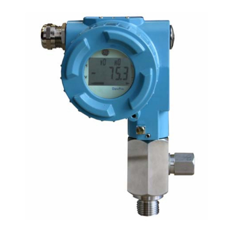
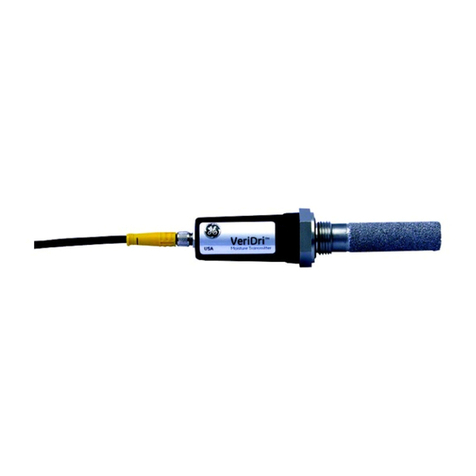
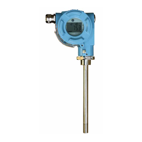
GE DewPro MMY31 User manual

GE Industrial
Sensing
DewPro MMY31
General Eastern Trace Moisture Transmitter
Installation and Operation Manual

GE Industrial
Sensing
DewPro MMY31
General Eastern Trace Moisture Transmitter
Installation and Operation Manual
A40251548A
September 2005
The
DewPro MMY31
is a General Eastern Instruments product. General Eastern Instruments has joined other
GE high-technology sensing businesses under a new name—GE Industrial Sensing.

iii
September 2005
Warranty Each instrument manufactured by GE Infrastructure Sensing, Inc. is
warranted to be free from defects in material and workmanship.
Liability under this warranty is limited to restoring the instrument to
normal operation or replacing the instrument, at the sole discretion of
GE Infrastructure Sensing, Inc. Fuses and batteries are specifically
excluded from any liability. This warranty is effective from the date of
delivery to the original purchaser. If GE Infrastructure Sensing, Inc.
determines that the equipment was defective, the warranty period is:
•one year for general electronic failures of the instrument
•one year for mechanical failures of the sensor
If GE Infrastructure Sensing, Inc. determines that the equipment was
damaged by misuse, improper installation, the use of unauthorized
replacement parts, or operating conditions outside the guidelines
specified by GE Infrastructure Sensing, Inc., the repairs are not
covered under this warranty.
The warranties set forth herein are exclusive and are in lieu of
all other warranties whether statutory, express or implied
(including warranties of merchantability and fitness for a
particular purpose, and warranties arising from course of
dealing or usage or trade).
Return Policy If a GE Infrastructure Sensing, Inc. instrument malfunctions within the
warranty period, the following procedure must be completed:
1. Notify GE Infrastructure Sensing, Inc., giving full details of the
problem, and provide the model number and serial number of the
instrument. If the nature of the problem indicates the need for
factory service, GE Infrastructure Sensing, Inc. will issue a RETURN
AUTHORIZATION number (RA), and shipping instructions for the
return of the instrument to a service center will be provided.
2. If GE Infrastructure Sensing, Inc. instructs you to send your
instrument to a service center, it must be shipped prepaid to the
authorized repair station indicated in the shipping instructions.
3. Upon receipt, GE Infrastructure Sensing, Inc. will evaluate the
instrument to determine the cause of the malfunction.
Then, one of the following courses of action will then be taken:
•If the damage is covered under the terms of the warranty, the
instrument will be repaired at no cost to the owner and returned.
•If GE Infrastructure Sensing, Inc. determines that the damage is not
covered under the terms of the warranty, or if the warranty has
expired, an estimate for the cost of the repairs at standard rates
will be provided. Upon receipt of the owner’s approval to proceed,
the instrument will be repaired and returned.

September 2005
iv
Table of Contents
Chapter 1: General System Information
Unpacking and Inspection . . . . . . . . . . . . . . . . . . . . . . . . . . . . . . . . . . . . . . . . . . . . . . . . . . . . . . . . . . . . . . 1-1
Unit Description . . . . . . . . . . . . . . . . . . . . . . . . . . . . . . . . . . . . . . . . . . . . . . . . . . . . . . . . . . . . . . . . . . . . 1-3
Theory of Operation . . . . . . . . . . . . . . . . . . . . . . . . . . . . . . . . . . . . . . . . . . . . . . . . . . . . . . . . . . . . . . . . . . . . 1-3
First 4–20mA Loop . . . . . . . . . . . . . . . . . . . . . . . . . . . . . . . . . . . . . . . . . . . . . . . . . . . . . . . . . . . . . . . . . 1-3
Planar Sensor . . . . . . . . . . . . . . . . . . . . . . . . . . . . . . . . . . . . . . . . . . . . . . . . . . . . . . . . . . . . . . . . . . . . . . 1-3
Calibration . . . . . . . . . . . . . . . . . . . . . . . . . . . . . . . . . . . . . . . . . . . . . . . . . . . . . . . . . . . . . . . . . . . . . . . . . 1-3
Chapter 2: Installation
Mounting the MMY31. . . . . . . . . . . . . . . . . . . . . . . . . . . . . . . . . . . . . . . . . . . . . . . . . . . . . . . . . . . . . . . . . . . 2-1
Wiring Configurations . . . . . . . . . . . . . . . . . . . . . . . . . . . . . . . . . . . . . . . . . . . . . . . . . . . . . . . . . . . . . . . . . . 2-3
Designing the Loop. . . . . . . . . . . . . . . . . . . . . . . . . . . . . . . . . . . . . . . . . . . . . . . . . . . . . . . . . . . . . . . . . 2-3
In a Normal Environment . . . . . . . . . . . . . . . . . . . . . . . . . . . . . . . . . . . . . . . . . . . . . . . . . . . . . . . . . . . 2-4
In Environments with Severe Electrical Noise . . . . . . . . . . . . . . . . . . . . . . . . . . . . . . . . . . . . . . . . 2-4
General Wiring Instructions . . . . . . . . . . . . . . . . . . . . . . . . . . . . . . . . . . . . . . . . . . . . . . . . . . . . . . . . . 2-5
Chapter 3: Troubleshooting
The Loop Current is Out of Range . . . . . . . . . . . . . . . . . . . . . . . . . . . . . . . . . . . . . . . . . . . . . . . . . . . . . . . 3-1
There Is No Current. . . . . . . . . . . . . . . . . . . . . . . . . . . . . . . . . . . . . . . . . . . . . . . . . . . . . . . . . . . . . . . . . . . . . 3-1
Chapter 4: Optional Display/User Interface
Installation. . . . . . . . . . . . . . . . . . . . . . . . . . . . . . . . . . . . . . . . . . . . . . . . . . . . . . . . . . . . . . . . . . . . . . . . . . . . . 4-1
Removing the Display . . . . . . . . . . . . . . . . . . . . . . . . . . . . . . . . . . . . . . . . . . . . . . . . . . . . . . . . . . . . . . 4-1
Programming Matrix . . . . . . . . . . . . . . . . . . . . . . . . . . . . . . . . . . . . . . . . . . . . . . . . . . . . . . . . . . . . . . . . . . . 4-2
Push Buttons - Special Functions . . . . . . . . . . . . . . . . . . . . . . . . . . . . . . . . . . . . . . . . . . . . . . . . . . . . . . . 4-4
Reset to “Normal” Display. . . . . . . . . . . . . . . . . . . . . . . . . . . . . . . . . . . . . . . . . . . . . . . . . . . . . . . . . . . 4-4
Display Only. . . . . . . . . . . . . . . . . . . . . . . . . . . . . . . . . . . . . . . . . . . . . . . . . . . . . . . . . . . . . . . . . . . . . . . . 4-4
Default Values . . . . . . . . . . . . . . . . . . . . . . . . . . . . . . . . . . . . . . . . . . . . . . . . . . . . . . . . . . . . . . . . . . . . . 4-4
Changing Values . . . . . . . . . . . . . . . . . . . . . . . . . . . . . . . . . . . . . . . . . . . . . . . . . . . . . . . . . . . . . . . . . . . 4-4
Matrix Functions . . . . . . . . . . . . . . . . . . . . . . . . . . . . . . . . . . . . . . . . . . . . . . . . . . . . . . . . . . . . . . . . . . . . . . . 4-5
Display and Output Mode. . . . . . . . . . . . . . . . . . . . . . . . . . . . . . . . . . . . . . . . . . . . . . . . . . . . . . . . . . . 4-5
Special Calibration . . . . . . . . . . . . . . . . . . . . . . . . . . . . . . . . . . . . . . . . . . . . . . . . . . . . . . . . . . . . . . . . . 4-6
Mode of Operation . . . . . . . . . . . . . . . . . . . . . . . . . . . . . . . . . . . . . . . . . . . . . . . . . . . . . . . . . . . . . . . . . 4-7
Chapter 5: Specifications
Technical Specifications . . . . . . . . . . . . . . . . . . . . . . . . . . . . . . . . . . . . . . . . . . . . . . . . . . . . . . . . . . . . . . . . 5-1
Optional Onboard Display with User Interface . . . . . . . . . . . . . . . . . . . . . . . . . . . . . . . . . . . . . . . . . . . 5-2
EMI/RFI . . . . . . . . . . . . . . . . . . . . . . . . . . . . . . . . . . . . . . . . . . . . . . . . . . . . . . . . . . . . . . . . . . . . . . . . . . . . . . . . 5-2
EMC . . . . . . . . . . . . . . . . . . . . . . . . . . . . . . . . . . . . . . . . . . . . . . . . . . . . . . . . . . . . . . . . . . . . . . . . . . . . . . . . . . . 5-2

Chapter 1

General System Information 1-1
September 2005
Unpacking and
Inspection
Upon receipt of the DewPro MMY31, examine the shipping carton
for broken or open packing, distortion, or any other evidence of
mishandling. If inspection indicates damage to the unit or any of its
components, notify the carrier (within 15 days of delivery) and
request an inspection.
Move the carton to a clean work area and unpack. The carton you
receive should contain:
•DewPro MMY31
•Installation and Operation Manual
•Calibration Certificate
Compare the last five numbers or letters on the model number (on the
product label shown in Figure 1-1 below) with the product structure
(see below) to ensure you have received everything you ordered.
Figure 1-1: DewPro MMY31 Product Label
GE Sensing
1100 Technology Park Dr.
Billerica, MA 01821 USA
Model:
S/N:
Supply:
Range:
Pressure Rating:
MMY31 - R8A2A

September 2005
1-2 General System Information
Table 1: Model Number Configuration
Certification/Approvals:
RStandard Certification (not certified)
AFM IS Cl. I, II, III, Div. 1; Grps. A-G
BFM XP Cl. I, Div. 1; Grps. A-D
CFM NI Cl. I, Div. 2, Grps. A-D; Cl. II, III, Div. 1; Grps. E-G
FATEX 3GEEx nA EEx 11C T4
SOther
Process Connection:
2¾” NPT-M compression fitting
3½” NPT-M compression fitting
4¾” x 16 “O” ring compression fitting (UNF thread)
6No mounting hardware
8G½ compression fitting with gasket
SOther
Protective Cap:
AStandard with 100 micron sintered filter
BWithout sintered filter
SOther
Enclosure Conduit:
1Enclosure Conduit M20 x 1.5-F with cable gland and plug
2Enclosure Conduit M20 x 1.5-F with ½” FNPT adapter and plug
SOther
Output Configuration/Dewpoint Range:
ATd –90°C to +10°C (–130°F to +50°F), no display, error 22 mA
BTd –90°C to +10°C (–130°F to +50°F), no display, error Hold
CTd –90°C to +10°C (–130°F to +50°F), no display, error 3.6 mA
D0-100 ppmv1 bar, no display, error 22 mA
E0-100 ppmv1 bar, no display, error Hold
F0-100 ppmv1 bar, no display, error 3.6 mA
GWith integral display, user interface
SOther
R 8 A 2 A Model Number example

General System Information 1-3
September 2005
Unit Description The DewPro MMY31 trace moisture transmitter is a loop-powered
dewpoint measuring device. The transmitter includes a sensor
element, a stainless steel probe, a weather-proof enclosure,
microprocessor electronics, and assorted fittings, all in a compact
assembly. It is designed to be installed “in-line.” Various types of
mounting hardware, such as flange and compression fittings, are
available for mounting into a process chamber or pipe.
An optional display with user interface feature allows the DewPro to
be configured by the user. See Chapter 4 for more information.
Theory of Operation
4–20mA Loop The DewPro MMY31 microcontroller operated electronics works
with a voltage supply of 12 to 28 VDC. At the nominal 24 VDC
supply, the maximum loop resistance is 600 ohms. The signal is
represented by the 4–20 mA loop current and is directly proportional
to the dewpoint temperature range in °C or °F. In the standard range,
4 mA corresponts to –90°C (–130°F) and 20 mA to +10°C (+50°F)
dewpoint temperature. The optional unit of measure is ppmvin the
standard range 0-100 ppmv, unless ordered differently
Planar Sensor The heart of the MMY31 is the planar sensor element. It incorporates
a superior aluminum oxide sensor that provides longer calibration
stability, excellent corrosion resistance, and improved speed of
response. The sensor, mounted on a ceramic substrate, also has a
reduced temperature coefficient.
Calibration Each DewPro is factory calibrated against precise NIST certified
moisture references and has an accuracy of ±2°C dewpoint at 25°C
temperature. For field validation, GE Sensing offers a unique
validation device. The MMY245 field validator connects to the
DewPro on site and offers a one-point or two-point correction.

Chapter 2

Installation 2-1
September 2005
Mounting the MMY31 Caution!
Before installing the unit, please read all the instructions.
The MMY31 is designed to be mounted onto pressurized
systems. Take all the necessary precautions when
mounting or removing the unit.
Choose a mounting location which allows enough clearance for the
use of tools and for connection of the field validator. Figure 2-1 below
shows the dimensions of the standard MMY31.
Figure 2-1: DewPro MMY31 Outline and Compression Fitting
5.43 (138)
4.25
(108)
9.45
(240) 0.79 (20)
0.50 (12.7)
Dimensions are in
inches (millimeters).
4.64 (118)* *without display

September 2005
2-2 Installation
Mounting the MMY31
(cont.)
Mount the MMY31 using a compression fitting connection. Be
certain that the tip of the probe does not touch the inside wall of the
pipe.
IMPORTANT: Ensure that your probe has a stainless steel ferrule,
which is required for use in pressurized systems.
Adjust the ferrule for a probe insertion length of 1” (minimum) and
tighten the compression fitting as follows (see Figure 2-2 below):
1. Hand-tighten the nut.
2. Then, using a wrench, tighten the nut 1½ turns. Now the fitting is
tight and can withstand pressure to 1750 psig (120 barg).
Figure 2-2: Mounting the MMY31
Minimum 1 in. (25 mm)

Installation 2-3
September 2005
Wiring Configurations Caution!
The DewPro system includes electronic components that
are susceptible to damage by static electricity. Use proper
handling procedures during the removal, installation, or
other handling of internal boards or devices.
Note: If the DewPro is equipped with an optional display/user
interface, please refer to Chapter 4.
Figure 2-3 below illustrates various power supplies and displays for
use with the DewPro MMY31.
Figure 2-3: System Configuration, Various
Designing the Loop When selecting a power supply, please note that the voltage at the +/-
terminal of the DewPro should not fall below 12 VDC. The maximum
loop resistance is an important measure for selection of the supply
voltage. Each device connected to the loop causes a voltage drop. For
instance, using a loop-powered display with an input impedance of
50 Ωwill cause a voltage drop of 1 VDC at 20 mA, using Ohm's law.
Connecting the loop to a PLC will cause a voltage drop across the
input.
When designing your loop, add up all voltage losses across the
devices connected to the loop and add 12 V. The sum will be the
minimum supply voltage required from the power supply. Calculate
with a 20% safety factor.
Sensing, such as Md102
Sensing
’
24 VDC (12...28 VDC)

September 2005
2-4 Installation
In a Normal Environment A standard two-wire, stranded cable can be used in a normal
environment to interconnect the DewPro with the power source.
In Environments with
Severe Electrical Noise
The DewPro MMY31 meets the EMC requirements of IEC 61326 for
equipment used in industrial locations. The MMY31 passed all tests
to the standards IEC 61000-4- to the performance criterion A. Test
details can be found in Chapter 5, Specifications.
Figure 2-4: Shielded Cable Wiring Diagram

Installation 2-5
September 2005
General Wiring
Instructions
To wire the DewPro MMY31:
1. Unscrew the cap on the terminal side of the unit (has a DewPro
label).
2. Loosen the cable gland located on the side of the unit.
3. Feed the cable through the conduit opening.
Note: Use a standard signal cable size.
4. Retighten the metal cable gland to meet IP 67 and to relieve any
stress on the wire.
5. Verify that a value between 12 and 28 VDC is across the terminals
marked + and –.
Note: This is the voltage that appears across the DewPro terminals,
not necessarily the power supply voltage due to voltage loss in
wire length, displays, indicators, etc.
6. In order to meet EMI/RFI immunity, a two-wire shielded cable
with a common foil shield layer is being used to power the
MMY31. Removing the insulation by 3 inches allows users to pull
back the foil, clamping it between the metal cable gland. The
ground wire must be connected to the internal grounding screw.
Figure 2-5: Electrical Connections
GND LOOP 1
–+
+
–
24 VDC Nominal (12-28V)
External GND/SHIELD Connection
Internal GND Connection

Chapter 3

Troubleshooting 3-1
September 2005
The Loop Current is Out
of Range
The loop current is outside the range of 4-20 mA, as shown on the
display or the current meter. For an example of error current at 22mA,
see below.
Solution The process dewpoint is out of range. If the dewpoint is above +10°C
(+50°F), the current will go to 22 mA. Apply dry air for 20 minutes.
If the dewpoint doesn't decrease, consult the factory.
If the dewpoint is below –90°C (–130°F), the current will go below
4 mA and then go to the error current, e.g. 22 mA. Expose the
DewPro to ambient air for several minutes. If the error remains, the
cause may be a defective sensor assembly or an electronics
malfunction. Consult the factory.
There Is No Current
Solution Check the voltage and polarity across +/- terminals with a DC
voltmeter. If the voltage is within 12-28 VDC, consult the factory.

Chapter 4
Other manuals for DewPro MMY31
1
Table of contents
Other GE Transmitter manuals
Popular Transmitter manuals by other brands

Eachine
Eachine DVR03 Product instruction manual

Lectrosonics
Lectrosonics WM quick start guide

YOKOGAWA
YOKOGAWA DpharpEJX vigilantplant EJX110 user manual

Sennheiser
Sennheiser SK 5012 instruction manual

AFRISO
AFRISO DMU 01 Translation of the original operating manual

Vibradorm
Vibradorm VFF/CDL-BF-07 operating instructions