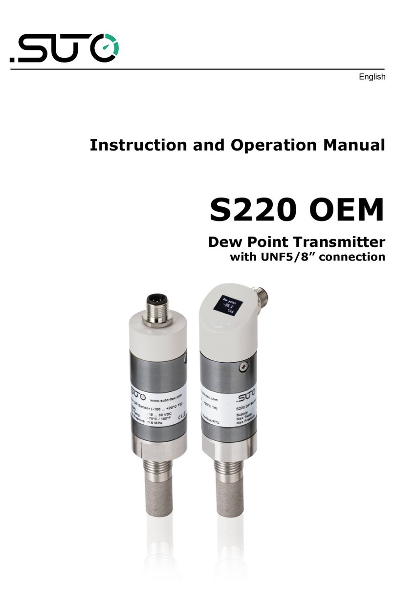
SUTO S217 OEM IO-Link Manual

English
Instruction and Operation Manual
S217 OEM IO-Link
Compact Dew Point Transmitter

Dear Customer,
Thank you for choosing our product.
The operating instructions must be read in full and carefully observed
before you start up the device. The manufacturer cannot be held liable
for any damage which occurs as a result of non-observance or non-
compliance with this manual.
Should the device be tampered with in any manner other than a
procedure which is described and specified in the manual, the warranty
is void and the manufacturer is e empt from liability.
The device is destined e clusively for the described application.
SUTO offers no guarantee for the suitability for any other purpose.
SUTO is also not liable for consequential damage resulting from the
delivery, capability or use of this device.
2 S217 OEM IO-Link

Ta le of contents
1 Safety instructions.......................................................................4
2 Registered trademarks.................................................................6
3 Application..................................................................................6
4 Features.....................................................................................6
5 Technical data.............................................................................7
5.1 General................................................................................7
5.2 Accuracy ..............................................................................8
6 Dimensional drawing....................................................................8
7 Electrical connection ...................................................................9
8 IO-Link Interface ......................................................................10
8.1 TD.....................................................................................10
8.2 Communication....................................................................10
8.3 Features.............................................................................10
8.4 Process Data ......................................................................11
8.5 ariables..............................................................................11
8.6 Events................................................................................13
8.7 Error Types.........................................................................14
9 Installation ...............................................................................15
9.1 Installation requirements......................................................15
9.2 Installation procedure ..........................................................15
9.3 Order information................................................................19
10 Calibration..............................................................................19
11 Maintenance............................................................................19
12 Disposal or waste.....................................................................20
S217 OEM IO-Link 3

1 Safety instructions
Please check if this instruction manual matches with the
product type.
Please observe all notes and instructions indicated in this
manual. It contains essential information which must be
observed before and during installation, operation and
maintenance. Therefore this instruction manual must be read carefully
by the technician as well as by the responsible user / qualified
personnel.
This instruction manual must be available at the operation site of the
dew point sensor at any time. In case of any obscurities or questions,
regarding this manual or the product, please contact the manufacturer.
WARNING!
Compressed air!
Any contact with quickly escaping air or ursting
parts of the compressed air system can lead to
serious injuries or even death!
•Do not e ceed the ma imum permitted pressure range (see
sensors label).
•Only use pressure tight installation material.
•Avoid that persons get hit escaping air or bursting parts of the
instrument.
•The system must be pressureless during maintenance work.
WARNING!
Voltage used for supply!
Any contact with energized parts of the product, may
lead to an electrical shock which can lead to serious
injuries or even death!
•Consider all regulations for electrical installations.
•The system must be disconnected from any power supply during
maintenance work.
•Any electrical work on the system is only allowed by authorized
qualified personal.
4 S217 OEM IO-Link

1 Safety instructions
ATTENTION!
Permitted operating parameters!
O serve the permitted operating parameters, any
operation exceeding this parameters can lead to
malfunctions and may lead to damage on the
instrument or the system.
•Do not e ceed the permitted operating parameters.
•Make sure the product is operated in its permitted limitations.
•Do not e ceed or undercut the permitted storage and operation
temperature and pressure.
General safety instructions
•It is not allowed to use the product in e plosive areas.
•Please observe the national regulations before/during installation
and operation.
Remarks
•It is not allowed to disassemble the product.
•Always use spanner to mount the product properly.
ATTENTION!
Measurement values can e affected y malfunction!
The product must e installed properly and
frequently maintained, otherwise it may lead to
wrong measurement values, which can lead to
wrong results.
Storage and transportation
•Make sure that the transportation temperature of the sensor is
between -30 ... +70°C.
•For transportation it is recommended to use the packaging which
comes with the sensor.
•Please make sure that the storage temperature of the sensor is
between -10 ... +50°C.
•Avoid direct UV and solar radiation during storage.
•For the storage the humidity must be <95% rH, no condensation.
S217 OEM IO-Link 5

2 Registered trademarks
SUTO® Registered trademark of SUTO iTEC
MODBUS® Registered trademark of the Modbus Organization,
Hopkinton, USA
HART®Registered trademark of the HART Communication
Foundation, Austin,USA
IO-Link®Registered Trademark of the PROFIBUS Nutzerorganisation
e.V., Germany
3 Application
The SUTO S217 OEM IO-Link Compact Dew Point Transmitter provides
reliable and long term stable dew point monitoring in industrial
applications. The newly developed device features improved signal and
stability in demanding industrial applications.
It’s designed for OEM applications in desiccant and refrigeration dryers.
The measured dew point is output via the IO-Link signal. The
parameters such as physical units, can be set e factory.
4 Features
•Small size makes it ideal for dryer installations
•Measures dew points down to –60ºC Td
•IO-Link communication interface
•IP65 casing provides robust protection in rough industrial
environment
•Very fast response time ensures safe and reliable indication
whenever dew points are out of valid ranges
•Can be installed directly into dryers through G 1/2” thread
•High accuracy of 1 … 2ºC Td dew point
•Withstands condensation
•M12 Connector
6 S217 OEM IO-Link

5 Technical data
5 Technical data
5.1 General
Measuring range
(model depending)
-60 ... +20°C Td
-20 ... +50°C Td
Accuracy ±1ºC Td [-5 … +50ºC]
±2ºC Td [-60 … -5ºC]
Pressure range -0.1 ... 5.0 MPa
-0.1 ... 35 MPa (optional)
Power supply 12 ... 30 VDC
Measured gas Non-corrosive gases
Ambient temperature -20 ... +50°C
Ambient humidity 0 ... 100% rH
Transport temperature -30 ... +70°C
Response time t90
(@ 4 l/min)
-40°C Td - > -20°C Td: 20 seconds
0°C Td - > -40°C Td: 120 seconds
Output signal IO-Link
IO-LINK Revision V1.1
Bitrate COM1
Minimum Cycle Time 40 ms
SIO Mode Supported No
Connection M12 connector, 5-pole (M12 plug included)
Casing Process connection: stain-less steel
Casing: Al alloy
Classification IP65
Process connection G ½” thread (ISO 228/1)
Sensor protection Stainless steel sinter filter pore size <30 µm
EMC According to IEC 61326-1
S217 OEM IO-Link 7

8 IO- ink Interface
8 IO-Link Interface
8.1 TD
Vendor ID 1490
Vendor Name SUTO iTEC
Vendor Te t www.suto-itec.com
Vendor URL www.suto-itec.com
Device ID 1038
8.2 Communication
IO-LINK Revision V1.1
Bitrate COM1
Minimum Cycle
Time
40 ms
SIO Mode
Supported
No
8.3 Features
Block
parametrization
Yes
Data storage Yes
10 S217 OEM IO-Link

8 IO- ink Interface
8.4 Process Data
Name Description /
Beschrei ung
Data
type
Bit
Offset
Bit
Length
Resol
ution
Unit
Dew point Pressure dew point
temperature value
Float32T 0 32 0.1 °F Td, °C Td
Temperature Temperature value Float32T 32 32 0.1 °F, °C
Alternative
Humidity unit
Alternative value with
humidity unit
Float32T 64 32 0.1 °C Td, °F Td,
mg/m³,
mg/m³ atm.
°C Td atm.
°F Td atm.
0.01 g/m³,
g/m³ atm.,
ppm(V)
0.001 % rH,g/kg
8.5 aria les
Name Descri
ption
Index Su index
itOffset
Data
Type
Length Access
Rights
Default Value
Range
Unit
Standard
Command
2 Sub 0 UInte
gerT
8bit WO (130)
Restore
Factory
Setting
(240) IO-
Link 1.1
system
test
command
240, Event
8DFE will
appear
(241) IO-
Link 1.1
system
test
command
241, Event
8DFE will
disappear
(242) IO-
Link 1.1
system
test
command
242, Event
8DFF will
appear
(243) IO-
Link 1.1
S217 OEM IO-Link 11

8 IO- ink Interface
system
test
command
243, Event
8DFF will
disappear
Device
Access
Lock
12 Sub 0 Recor
dT
16bit RW
Data
Storage
Lock
bitOffs 1 Boole
anT
1 Bit (0)
Vendor
Name
16 Sub 0 String
T
ma 12 RO SUTO
iTEC
Vendor
Te t
17 Sub 0 String
T
ma 18 RO www.su
to-
itec.co
m
Product
Name
18 Sub 0 String
T
ma 6 RO S217
Product
ID
19 Sub 0 String
T
ma 6 RO S217
Product
Te t
20 Sub 0 String
T
ma 24 RO Dew
point
sensor
IO-LINK
Serial
Number
21 Sub 0 String
T
ma 8 RO 123456
78
Hardware
Version
22 Sub 0 String
T
ma 5 RO 1.00
Firmware
Version
23 Sub 0 String
T
ma 5 RO V1.0
Applicatio
n Specific
Tag
24 Sub 0 String
T
ma 16 RW S217-
123456
Device
Status
36 Sub 0 UInte
gerT
8bit RO (0)
Device
is OK
Detailed
Device
Status
37 Sub 0 String
T
ma 5 RO 00 00
00 h
FOU2 OUT 2
behavio
ur in
case of
fault
532 Sub 0 UInte
gerT
8bit RW (4) OFF (2) ON
(4) OFF
Temperat
ure unit
Selectio
n of the
551 Sub 0 UInte
gerT
8bit RW (1) °C (1) °C
(2) °F
12 S217 OEM IO-Link

8 IO- ink Interface
temper
ature
unit
Dewpoint
alternate
unit
Selectio
n of
dew
point
sensor
alternat
e unit
553 Sub 0 UInte
gerT
8bit RW (3) % (3) %
(4) °C Td
(7) mg/m³
(8) g/kg
(9) g/m³
(30)
ppm(V)
(31) °C Td
atm.
(54) g/m³
atm.
(55)
mg/m³
atm.
DPStaticP
ressure
Dew
point
sensor
static
pressur
e, unit
is fi ed
as
bar(g)
554 Sub 0 Float3
2T
4 byte RW 6.0 0.0-100.0
8.6 Events
Code Name Type Description
35856 d / 8C
10 h
Process variable
range over-run
Warning Process data uncertain
35888 d / 8C
30 h
Process variable
range under-run
Warning Process data uncertain
36350 d / 8D
FE h
Test Event 1 Warning Event appears by setting inde 2 to value 240,
Event disappears by setting inde 2 to value 241
36351 d / 8D
FF h
Test Event 2 Warning Event appears by setting inde 2 to value 242,
Event disappears by setting inde 2 to value 243
S217 OEM IO-Link 13

8 IO- ink Interface
8.7 Error Types
Error Code Name Description
32768 d / 80 00 h Device application error -
no details
Service has been refused by the device
application and no detailed information of
the incident is available
32785 d / 80 11 h Inde not available Access occurs to a not e isting inde
32786 d / 80 12 h Subinde not available Access occurs to a not e isting subinde
32800 d / 80 20 h Service temporarily not
available
Parameter is not accessible due to the
current state of the device application
32803 d / 80 23 h Access denied Write access on a read-only parameter
32816 d / 80 30 h Parameter value out of
range
Written parameter value is outside its
permitted value range
32819 d / 80 33 h Parameter length overrun Written parameter length is above its
predefined length
32820 d / 80 34 h Parameter length
underrun
Written parameter length is below its
predefined length
32821 d / 80 35 h Function not available Written command is not supported by the
device application
32898 d / 80 82 h Application not ready Read or write service is refused due to a
temporarily unavailable application
14 S217 OEM IO-Link

9 Installation
9 Installation
Before installing the device, please make sure that all components listed
below are included in your package.
Qty Description Item No.
1 S217 OEM IO-Link Compact
Dew Point Transmitter
Model specific (See section 9.3.)
1 M12 Plug No P/N
1 Instruction manual No P/N
1 Calibration certificate No P/N
9.1 Installation requirements
The flowing air or gas must pass the sensor tip for a proper
measurement. This can be realized with a measurement chamber. For a
installation without measuring chamber you need to concern the
installation depth which is described in the ne t chapter.
9.2 Installation procedure
The following steps e plain the procedure of an appropriate installation.
Installation with the measurement cham er A699 3491
1. Mount the device on the
measurement chamber by
using the G1/2” connection.
2. Make sure the device is tightly
sealed, therefore the sealing
ring on the device must be
used.
3. Connect the measuring
chamber to the compressed
air system using a quick
connector. Make sure the
device is screwed on the
chamber before connecting.
The measurement chamber
will create a purge flow.
S217 OEM IO-Link 15

9 Installation
Installation with the y-pass measurement cham er A699 3493
For the model A699 3493, there are two installation methods:
Method 1: Full pass through by-pass installation
This method is to be used when the full air flow is passing through the
measuring chamber.
1. Connect the inlet of the chamber using a 6 mm teflon hose to your
system.
Note: The full flow must pass the measuring chamber. Ensure a
certain flow rate to get fast response time.
2. Connect the outlet of the chamber to your system using the 6 mm
hose quick connector.
See below figure for details.
16 S217 OEM IO-Link

9 Installation
Method 2: By-pass installation
Note : In order to use the measurement chamber in a by-pass you
must ensure a pressure difference between P1 and P2 as indicated in
the picture below.
1. Connect the inlet of the chamber to your pipe system.
2. Connect the outlet of the chamber to your pipe system where the
pressure is known to be lower than the inlet pressure.
Note : The pressure difference P1 > P2 is needed to create a by-pass
flow through the chamber. If there is no pressure difference between P1
and P2, there will be no flow through the chamber and therefore the
response time will be very slow or the device will not even respond at
all to the dew point changes.
S217 OEM IO-Link 17

9 Installation
Installation of the device without measurement cham er
Full flow installation. The sensor is in the
pipe.
•Install the sensor only if
the system is
pressureless.
•Not less than 1/3 of the
sensor tip should be inside
of the pipe. For this please
check the size of the
nozzle.
•The inner thread must be
G 1/2”.
Remarks
Please install the sensor only
in the recommended area
like you can see in the
picture. An upside down
installation is not permitted.
Please consider that the
distance to the vertical level
must be >30°.
Removal of the device
To remove the device unscrew the device from the measurement
chamber or from the nozzle. Please observe that the system is
pressureless when the device is removed.
18 S217 OEM IO-Link

9 Installation
9.3 Order information
Order no. Description
S699 2180 S217 OEM Compact Dew Point Transmitter, IO-Link,
-60 ... +20 °C Td, G1/2" thread, 5.0 MPa, M12 connector,
including M12 plug
S699 2181 S217 OEM Compact Dew Point Transmitter, IO-Link,
-20 ... +50 °C Td, G1/2" thread, 5.0 MPa, M12 connector,
including M12 plug
A1390 S217, customized measuring range
A1391 S217, high pressure option 35 MPa (350 bar)
A699 3491 Measuring chamber for easy installation in compressed air
system up to 15 bar
A699 3493 Measuring chamber bypass type (in and out 6 mm hose
connection)
10 Cali ration
The device is calibrated e work. The e act calibration date is printed on
the certificate which is supplied together with the device. The accuracy of
the device is regulated by the on site conditions, parameters like oil, high
humidity or other impurities can affect the calibration and furthermore
the accuracy. However we recommend to calibrate the instrument at
least once per year. The calibration is e cluded from the instruments
warranty. For this please contact the manufacturer.
11 Maintenance
Please observe from time to time the sinter cap. If it appears to be
dirty, it is recommended to replace it for this please contact the
manufacturer.
ATTENTION!
Contaminated filters can lead to longer response
time and to wrong measurements.
S217 OEM IO-Link 19

12 Disposal or waste
Electronic devices are recyclable material and do not
belong in the household waste.
The sensor, the accessories and its packings must be
disposed according to your local statutory requirements.
The dispose can also be carried by the manufacturer of the
product, for this please contact the manufacturer.
SUTO iTEC GmbH
Grißheimer Weg 21
D-79423 Heitersheim
Germany
SUTO iTEC (ASIA) Co., Ltd.
Room 10, 6/F, Block B, Cambridge Plaza
188 San Wan Road, Sheung Shui, N.T.
Hong Kong
Tel: +49 (0) 7634 50488 00
Fa : +49 (0) 7634 50488 19
Email: [email protected]
Website: http://www.suto-itec.com
Tel: +852 2328 9782
Fa : +852 2671 3863
Email: [email protected]
Website: http://www.suto-itec.com
All rights reserved © Modifications and errors reserved
S217_IO-Link_im_en_2022-1-1
20 S217 OEM IO-Link
Table of contents
Other SUTO Transmitter manuals
Popular Transmitter manuals by other brands

Allen-Bradley
Allen-Bradley 837TH-N1 Series installation instructions

Honeywell
Honeywell oneWireless XYR 6000 user manual

Artel
Artel FiberLink 3350 Series Installation and operation manual

Iluv
Iluv i707 instruction manual

Crestron
Crestron DigitalMedia 8G+ DM-TX-201-C Do guide

Emerson
Emerson Rosemount OCX 8800 quick start guide