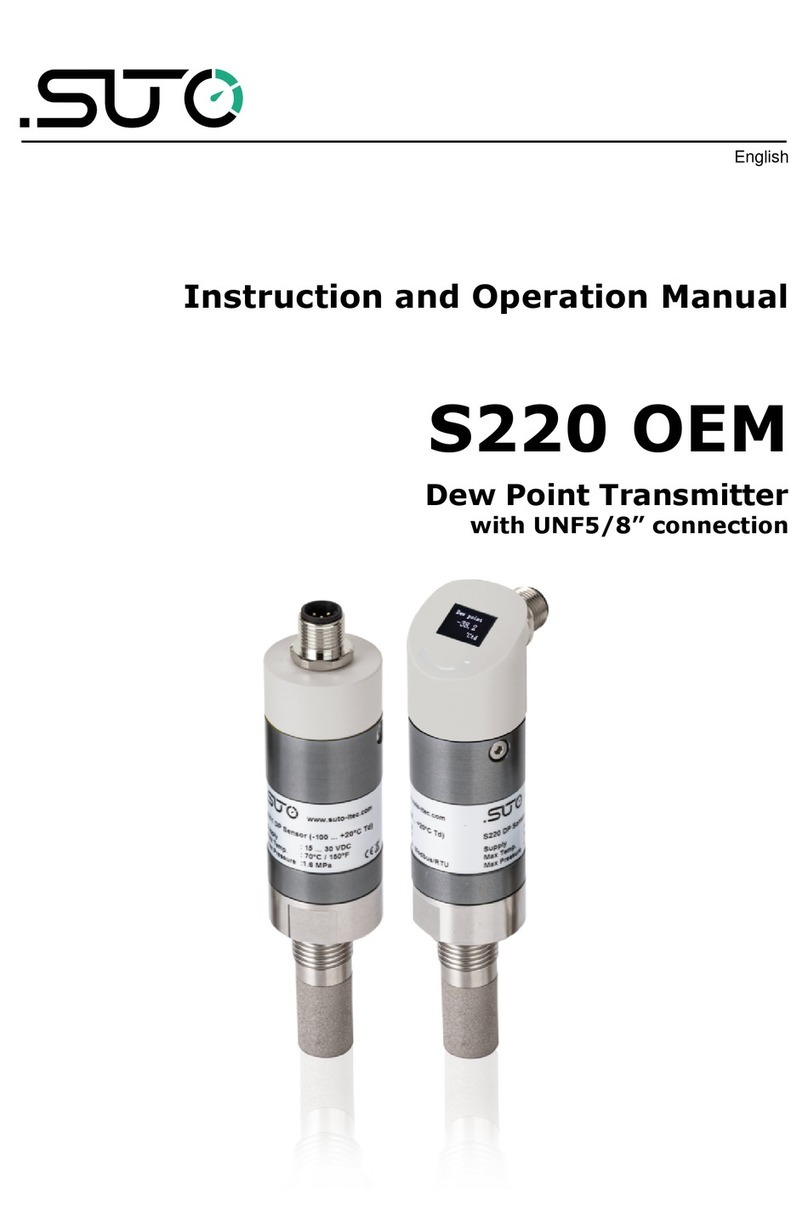
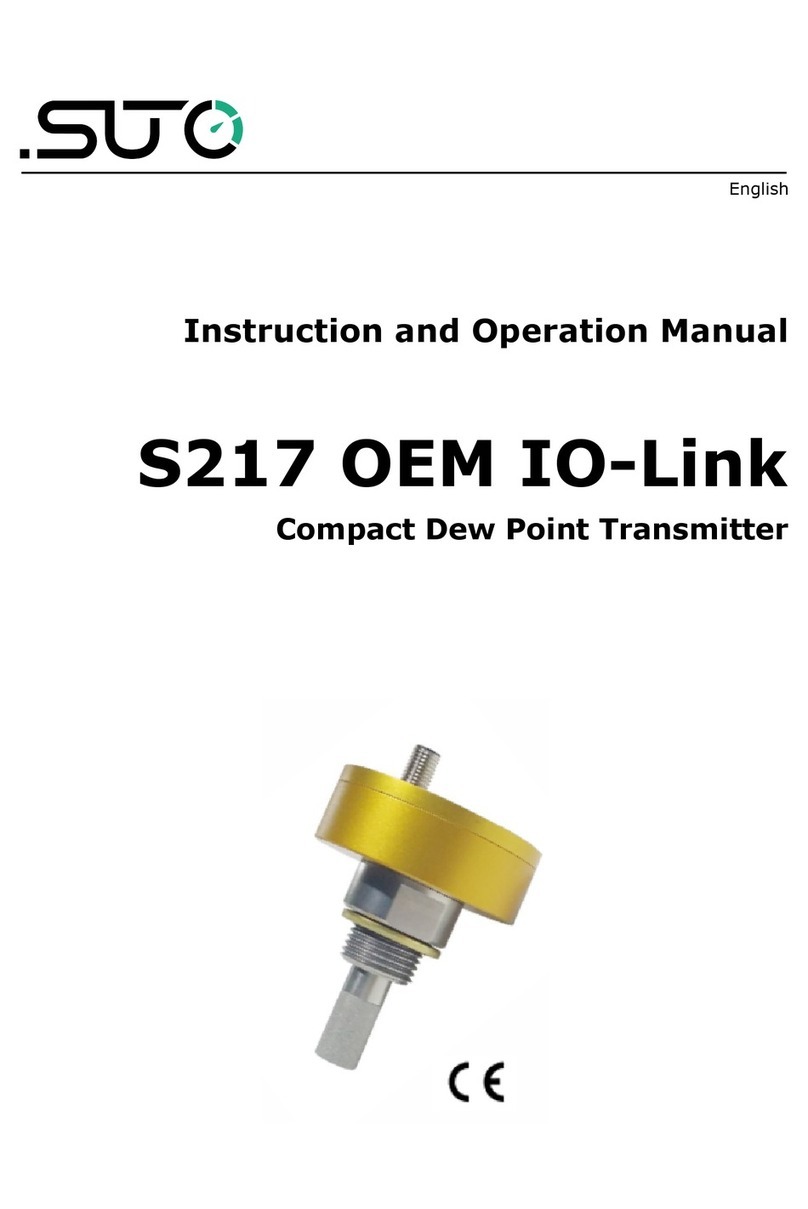
SUTO S230 Manual

English
Instruction and Operation Manual
S230/S231
S230 Ex/S231 Ex
Dew Point Transmitter for Ex pplications
The Dew Point Transmitter with optional hazardous approval for applications in
demanding industrial applications and hazardous environments.

Dear Customer,
Thank you for choosing our product.
The operating instructions must be observed before you start up the
device. The manufacturer cannot be held liable for any damage which
occurs as a result of non observance or non compliance with this
manual.
Should the device be tampered with in any manner other than a
procedure which is described and specified in the manual, the warranty
is cancelled and the manufacturer is exempt from liability.
The device is destined exclusively for the described application.
SUTO offers no guarantee for the suitability for any other purpose.
SUTO is also not liable for consequential damage resulting from the
delivery, capability or use of this device.
S230/S231
2 S230 Ex/S231 Ex

Table of contents
1 Safety Instructions......................................................................5
2 Registered Trademarks................................................................8
3 RF Exposure Information and Statement........................................9
4 Application...............................................................................10
5 Features...................................................................................10
6 Technical Data..........................................................................11
6.1 General.....................................................................................11
6.2 Electrical Data............................................................................11
6.3 Output Signals...........................................................................12
6.4 Accuracy...................................................................................12
6.5 Operating conditions .................................................................12
7 Dimensional Drawing................................................................13
8 Installation...............................................................................14
8.1 General Installation Considerations................................................14
8.2 Medium Temperature ..................................................................14
8.3 Cable Entries..............................................................................14
8.4 Fuse.........................................................................................14
8.5 Determination of the Installation Point...........................................14
8.6 Installation Requirements............................................................15
8.7 Installation to Compressed Air / Gas .............................................15
8.8 Electrical Connection .................................................................17
9 Ex Version S230 Ex/S231 Ex......................................................17
9.1 Special Conditions for the Ex Version.............................................17
9.2 Examination Certificates, Certificate of Conformity...........................18
9.3 Intrinsic Safety Ratings and Parameters.........................................18
9.4 Name Plates...............................................................................18
9.5 Installation................................................................................19
9.5.1 General Installation Considerations......................................19
9.5.2 Cable Entries....................................................................19
9.6 Potential Equalization..................................................................20
9.7 Service Kit.................................................................................20
9.8 Back Cover / Security Seal...........................................................20
9.9 Used Standards..........................................................................21
10 Signal Outputs........................................................................22
10.1 Analog Output..........................................................................22
10.2 Modbus Interface .....................................................................22
10.3 Connection between S230/S231 Outputs and Customer Equipment. .25
11 Optional Extra Accessories........................................................26
11.1 Measuring Chambers ................................................................26
11.2 Service Kit...............................................................................26
S230 Ex/S231 Ex 3

12 Calibration..............................................................................27
13 Maintenance...........................................................................27
14 Disposal or Waste....................................................................27
S230/S231
4 S230 Ex/S231 Ex

1 Safety Instructions
Please check if this instruction manual matches with the
product type.
Please observe all notes and instructions indicated in this
manual. It contains essential information which must be
observed before and during installation, operation and
maintenance. Therefore this instruction manual must be read carefully
by the technician as well as by the responsible user / qualified
personnel.
This instruction manual must be available at the operation site of the
dew point transmitter at any time. In case of any obscurities or
questions, regarding this manual or the product, please contact the
manufacturer.
This document contains important information for
the installation and operation of the dew point
transmitter in explosive environments (See chapter
8). Please read the instructions carefully and follow
the instructions mentioned in this manual.
•Do not exceed the maximum permitted pressure range (see
sensors label).
•The installation and the supply connection must be done in
compliance with national regulations.
•The compliance with all of the technical data of the device is
mandatory (see also nameplate).
•When opening the enclosure make sure that no dust or moisture
enters into the casing.
•Ensure that cable entries are tightly sealed
•Materials which come in contact with the medium are of stainless
steel and of sealing rubber NBR.
W RNING!
Compressed air!
ny contact with quickly escaping air or bursting
parts of the compressed air system can lead to
serious injuries or even death!
S230 Ex/S231 Ex 5

1 Safety Instructions
•Do not use S230 / S231 in hazardous environment without the
optional hazardous approval rating.
•Do not exceed the maximum permitted pressure range.
•Only use pressure tight installation material.
•Avoid that persons get hit escaping air or bursting parts of the
instrument.
•The system must not be pressurized during maintenance work.
•Consider all regulations for electrical installations.
•The system must be disconnected from any power supply during
maintenance work.
•Any electrical work on the system is only allowed by authorized
qualified personal.
TTENTION!
Permitted operating parameters!
Observe the permitted operating parameters, any
operation exceeding this parameters can lead to
malfunctions and may lead to damage on the
instrument or the system.
•Do not exceed the permitted operating parameters.
•Make sure the product is operated in its permitted limitations.
•Do not exceed or undercut the permitted storage and operation
temperature and pressure.
•The product should be maintained and calibrated frequently, at
least annually.
General safety instructions
•It is not allowed to use the product S230 / S231 in explosive
areas.
•Please observe the national regulations before/during installation
and operation.
•For S230 Ex/S231 Ex:
◦Repairs of the flameproof joints may only be made by the
manufacturer or on behalf of the manufacturer and on his own
responsibility. Repair in compliance with the values in IEC
60079 1 is not accepted.
S230/S231
6 S230 Ex/S231 Ex

1 Safety Instructions
◦The external earth connection facility shall be connected
reliably.
◦The equipment has been assessed with a Um of 30V DC and
shall be installed in accordance with the latest installation
requirements of IEC 60079 14 for intrinsically safe equipment
for EPL “Gb”.
◦The cable entries could be connected only with the cable gland
which is HSK M Ex d Series cable gland from Hummel with
M16*1.5 size, Certificate number is IECEx KEM 07.0013X.
◦The end user shall make sure the medium temperature range
has no significant influence on the ambient temperature so that
may cause a failure of explosion proof performance of the
equipment.
◦The equipment must only be wiped with a damp cloth.
Remarks
•It is not allowed to disassemble the product.
•Always use spanner to mount the product properly.
TTENTION!
Measurement values can be affected by malfunction!
The product must be installed properly and
frequently maintained, otherwise it may lead to
wrong measurement values, which can lead to
wrong results.
Storage and transportation
•Make sure that transportation temperature of the device is
between 30°C ... +70°C.
•For storage and transportation it is recommended to use the
packaging which comes with the device.
•Please make sure that the storage temperature of the device is
between 0°C ... +50°C.
•Avoid direct UV and solar radiation during storage.
•For the storage the humidity must be <95% rH, no condensation.
S230 Ex/S231 Ex 7

3 RF Exposure Information and Statement
This equipment complies with FCC RF radiation exposure limits set forth
for an uncontrolled environment. This equipment should be installed
and operated with minimum distance of 20 cm between the radiator and
your body.
This device complies with part 15 of the FCC rules. Operation is subject
to the following two conditions: (1) this device may not cause harmful
interference, and (2) this device must accept any interference received,
including interference that may cause undesired operation.
NOTE: The manufacturer is not responsible for any radio or TV
interference caused by unauthorized modifications to this equipment.
Such modifications could void the user’s authority to operate the
equipment.
NOTE: This equipment has been tested and found to comply with the
limits for a Class B digital device, pursuant to part 15 of the FCC Rules.
These limits are designed to provide reasonable protection against
harmful interference in a residential installation. This equipment
generates uses and can radiate radio frequency energy and, if not
installed and used in accordance with the instructions, may cause
harmful interference to radio communications. However, there is no
guarantee that interference will not occur in a particular installation. If
this equipment does cause harmful interference to radio or television
reception, which can be determined by turning the equipment off and
on, the user is encouraged to try to correct the interference by one or
more of the following measures:
•Reorient or relocate the receiving antenna.
•Increase the separation between the equipment and receiver.
•Connect the equipment into an outlet on a circuit different from
that to which the receiver is connected.
•Consult the dealer or an experienced radio/TV technician for help.
•This device and its antenna(s) must not be co located or operating
in conjunction with any other antenna or transmitter.
S230 Ex/S231 Ex 9

4 Application
4 pplication
The S230/S231/S230 Ex/S231 Ex is a dew point transmitter which is
designed to monitor the dew point in hazardous environments and
industrial application within the permissible operating parameters.
The S230/S231/S230 Ex/S231 Ex measures the following values:
•Dew point of the compressed air or gas.
•Temperature of the compressed air or gas.
•Other selectable moisture units such as: relative humidity [% rH],
absolute humidity [g/m3, mg/m3], humidity grade [g/kg], humidity
ratio by volume [ppmV] of the compressed air or gas.
The default factory settings are: temperature in °C and dew point in
°C Td. Other units can be programmed by the service kit.
5 Features
•Double sensor technology for best accuracy over the whole range
from 100°C ... +20°C Td dew point in S230 and S230 Ex
•Robust industrial design
•Outputs: 1 x 4 ... 20 mA, RS 485 (Modbus).
•IP67 casing provides robust protection in rough industrial
environment
•Very fast response time ensures safe and reliable indication
whenever dew points are out of valid ranges
•High accuracy
S230/S231
10 S230 Ex/S231 Ex

6 Technical Data
6 Technical Data
6.1 General
Parameters Dew point:°C Td or °F Td
Temperature:°C or °F
Other moisture units:
Relative humidity [% rH]
Absolute humidity [g/m3, mg/m3]
Humidity grade [g/kg]
Humidity ratio by volume [ppmV]
Sensor S230/S230 Ex: QCM and polymer sensor
S231/S231 Ex: Polymer sensor
Measuring range Dew point:
•S230/S230 Ex: 100°C ... +20°C Td
•S231/S231 Ex: 50°C ... +20°C Td
Temperature: 30 ... +70°C
Response time T90 ≤ 240 sec ( 20°C Td → 60°C Td)
≤ 30 sec ( 60°C Td → 20°C Td)
Casing material Process connection: stainless steel
Casing: aluminium alloy
Protection class IP67
Approvals II 2G Ex db ib IIC T4 Gb
II 2D Ex ib tb IIIC T135°C Db
CE
Dimensions See dimensional drawing on page 13.
Process connection G ½” thread (ISO 228/1)
Weight 770 g
6.2 Electrical Data
Power supply 10 ... 30 VDC, 45 mA @ 24 VDC
S230 Ex/S231 Ex 11

6 Technical Data
6.3 Output Signals
Analogue output 4 ... 20 mA, isolated
Analogue output
scaling
(default: dew point)
S230/S230 Ex: 4 mA = 100°C Td
20 mA = +20°C Td
S231/S231 Ex: 4 mA = 50°C Td
20 mA = +20°C Td
RS 485 Modbus/RTU
6.4 ccuracy
Accuracy Dew point ±1°C Td (0 ... 20 °C Td)
±2°C Td ( 60 ... 0 °C Td)
±3°C ( 100 ... 60 °C Td)
Temperature 0.3°C
Repeatability ±1.0°C Td
Stated accuracy at Ambient/process temperature: 23°C ± 3°C
Ambient/process humidity <95% rH, no
condensation
Airflow > 2 l/min at sensor tip
6.5 Operating conditions
Medium Air, Argon, O₂, N₂, CO₂
Medium quality ISO 8573 1: 4.6.3 or better
Medium temperature 30°C ... +70°C
Medium humidity ≤ 20 °C Td
Operating pressure 0.1 ... 1.6 MPa(g) (S230/S230 Ex)
0.1 ... 35 MPa(g) (S231/S231 Ex)
Ambient temperature 20°C ... +50°C
Ambient humidity 0 ... 100 % rH
Storage temperature 20°C ... +50°C
Transport temperature 30°C ... +70°C
S230/S231
12 S230 Ex/S231 Ex

8 Installation
8 Installation
8.1 General Installation Considerations
•The Dew Point Transmitter is only allowed to be used in the
permitted temperature class.
•Cables, drain plugs, cable glands and cable entries must be suitable
and certified.
8.2 Medium Temperature
TTENTION!
The minimum temperature for compressed air or gas
is –30°C.
8.3 Cable Entries
The cable glands/entries must be secured to prevent working loose and
the seals must be installed immediately adjacent to the casing.
Please ensure that the cable entries and cable glands are leak tight!
The cables used must be manufactured in a way that the build up of
electrostatic charges are avoided!
8.4 Fuse
The power supply for the transmitter needs to have a fuse with
following specification:
Voltage 16 to 30 VDC, fuse 0.5 A slow blow (cutoff capacity 1500 A)
8.5 Determination of the Installation Point
In order to maintain the accuracy stated in the technical data, the
device must be installed correctly. The air must flow on to the sensor
tip, otherwise it will lead to wrong measurement values. For further
instructions, please read the next chapter carefully.
Please consider that enough space exists at your site for a adequate
installation as described in this manual.
S230/S231
14 S230 Ex/S231 Ex

8 Installation
TTENTION!
Wrong measurement is possible, if the device is not
installed correctly.
It is strongly recommend not to install S230/S231/
S230 Ex/S231 Ex permanently in wet applications
such as the compressor outlet.
8.6 Installation Requirements
The flowing air or gas must pass the sensor tip for a proper
measurement. This can be realized with a measurement chamber. For a
installation without measuring chamber you need to concern the
installation depth which is described in the next chapter.
8.7 Installation to Compressed ir / Gas
The following steps explain the procedure of an appropriate installation.
Install the device with measurement chamber
1. Connect the device with
the measurement
chamber.
2. Connect the device and
the measurement
chamber with the fast
connector.
ttention:
For explosive gas application,
installation with measurement
chamber is not allowed!
S230 Ex/S231 Ex 15

8 Installation
Install the device without measurement chamber
•Install the device only if
the system is not
pressurized.
•Not less than 1/3 of the
sensor tip should be
inside of the pipe. For
this please check the
size of the nozzle.
•The inner thread must
be G 1/2”.
Remarks
Please install the transmitter
only in the recommended
area as you can see in the
picture. An upside down
installation is not permitted.
Please consider that the
distance to the vertical level
must be >30°.
Removal of the device
To remove the transmitter unscrew the transmitter from the
measurement chamber or from the nozzle. Please observe that the
system is not pressurized when the transmitter is removed.
S230/S231
16 S230 Ex/S231 Ex

8 Installation
8.8 Electrical Connection
VBNegative power supply
+VBPositive power supply
D+ Modbus D+
D Modbus D
G Modbus Ground
Earth, shielding connection
I+ 4 ... 20 mA positive connection
I 4 ... 20 mA negative connection
9 Ex Version S230 Ex/S231 Ex
9.1 Special Conditions for the Ex Version
•Ambient temperature range between 20°C and +50°C.
•Do not separate when energized.
•Do not open in hazardous area.
•Integration into the potential equalization is carried out via the
installation.
•The device must only be operated with a fuse with a 1500 A cut
off capacity.
•The operating instructions must be observed.
•The intrinsically safe maximum values can be found in Section 7.3.
Special ttention!
Integration into the potential equalization is carried out via
the installation.
The device must be connected to the potential equalization
system.
S230 Ex/S231 Ex 17

9 Ex Version S230 Ex/S231 Ex
9.2 Examination Certificates, Certificate of Conformity
The system meets the fundamental health and safety requirements for
the design and construction of devices and protective systems intended
for use in potentially explosive atmospheres in accordance with directive
2014/34/EU.
9.3 Intrinsic Safety Ratings and Parameters
Electrical parameters supply and signal circuit in type of protection
intrinsic safety Ex ib IIC:
•Um: 30V DC
•Max Input power: 1 W
•Max available short circuit current: 1 A
9.4 Name Plates
Below are the name plates when ordered with hazardous approval.
TEX:
Manufacturer: SUTO iTEC (China) Co.Ltd.
Address:No. 1001 Zhongshanyuan Rd., Nanshan, Shenzhen, PRC
S230/S231
18 S230 Ex/S231 Ex

9 Ex Version S230 Ex/S231 Ex
IECEx:
Manufacturer: SUTO iTEC (China) Co.Ltd.
Address: No. 1001 Zhongshanyuan Rd., Nanshan, Shenzhen, PRC
9.5 Installation
9.5.1 General Installation Considerations
Cables and pipe entries must be certified (Ex d IIC) and must be
suitable for operating temperatures of up to 105°C. When using pipe
entries, the associated sealing equipment must be fitted directly at the
housing.
9.5.2 Cable Entries
The cable glands/entries must be secured to prevent working loose and
the seals must be installed immediately adjacent to the casing.
Please ensure that the cable entries and cable glands are leak tight!
The cables used must be manufactured in a way that the build up of
electrostatic charges are avoided!
S230 Ex/S231 Ex 19

9 Ex Version S230 Ex/S231 Ex
Only following cable gland is allowed to be used and can be ordered at
SUTO:
Hummel
Order No. Description Thread
size Cable entry
Gland 1.622.1600.50 HSK M Ex d/Metr M16 x 1.5 5 ... 10 mm
Cable outer diameter must be between 5.0 … 10 mm!
9.6 Potential Equalization
For the safety of the operation in explosive environment the potential
equalization is very important. The device has a screw terminal outside
the enclosure to connect the earth signal.
The device can also be integrated to the equalization through the
pipeline as long the earth connection is conform to regulations.
9.7 Service Kit
No connection of service kit or any other devices are permitted if the
atmosphere is considered to be explosive.
Alternatively device settings can be done through the Modbus interface
from a remote location (non explosive area) if the cable is installed.
Please contact our service for available devices and software.
9.8 Back Cover / Security Seal
The Back cover of the device is secured with a screw to avoid the
opening of the cover by unauthorized persons. Please ensure that the
security screw is tighten up after finishing the installation!
S230/S231
20 S230 Ex/S231 Ex
This manual suits for next models
3
Table of contents
Other SUTO Transmitter manuals
Popular Transmitter manuals by other brands

Allen-Bradley
Allen-Bradley 837TH-N1 Series installation instructions

Honeywell
Honeywell oneWireless XYR 6000 user manual

Artel
Artel FiberLink 3350 Series Installation and operation manual

Iluv
Iluv i707 instruction manual

Crestron
Crestron DigitalMedia 8G+ DM-TX-201-C Do guide

Emerson
Emerson Rosemount OCX 8800 quick start guide