Sutter CURIS flow User manual

INSTRUCTIONS FOR USE
CURIS®flow Irrigation pump
REF 350950


Read carefully before use
and retain for future reference!

CURIS®flow Instructions for Use
i
Table of contents
1EXPLANATION OF SYMBOLS AND ABBREVIATIONS ...................................................................... 1
2SYSTEM DESCRIPTION.................................................................................................................... 3
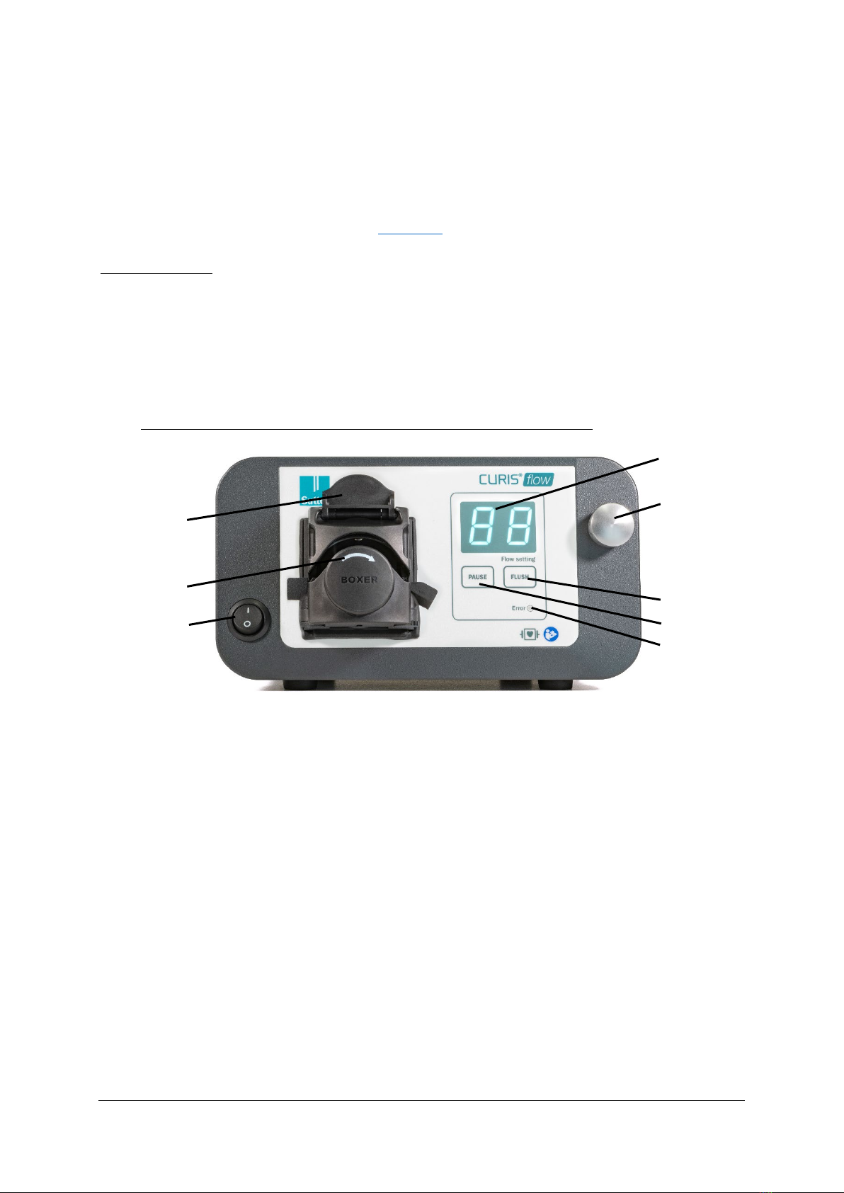
2.1 Function and meaning of the display and control elements................................................ 3
2.2 Intended use ........................................................................................................................... 5
2.2.1 Purpose ........................................................................................................................... 5
2.2.2 Contraindications ........................................................................................................... 5
2.2.3 Side effects ..................................................................................................................... 5
2.2.4 Essential performance characteristics ......................................................................... 5
3COMMISSIONING ............................................................................................................................ 5
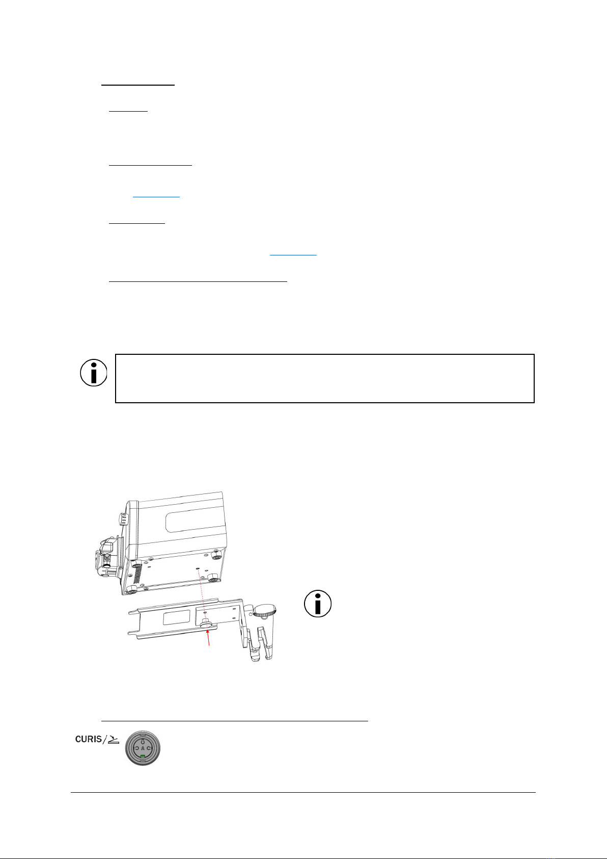
3.1 Setup for use with the corresponding footswitch ................................................................. 5
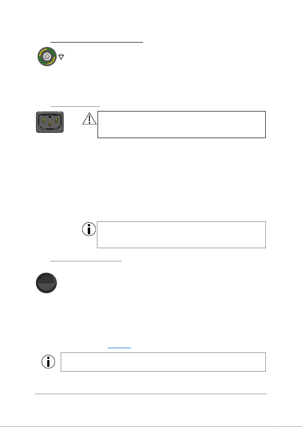
3.2 Potential equalization connection ......................................................................................... 6
3.3 Mains connection.................................................................................................................... 6
3.4 System start and self-test....................................................................................................... 6
3.5 Inserting the bipolar cord and tubing set .............................................................................. 7
4OPERATION...................................................................................................................................... 8
4.1 Additional operating functions ............................................................................................... 9
4.2 Decommissioning..................................................................................................................10
5SAFETY MEASURES AND PRECAUTIONS .....................................................................................10
6CLEANING AND DISINFECTION.....................................................................................................11
7ERROR DISPLAY AND TROUBLESHOOTING .................................................................................11
7.1 Maintenance and repair .......................................................................................................14
8ACCESSORIES................................................................................................................................14
9TRANSPORTATION AND PACKAGING ...........................................................................................15
9.1 Incoming inspection and transport damage .......................................................................15
9.2 Claims for damages..............................................................................................................16
9.3 Returns ..................................................................................................................................16
9.4 Device disposal .....................................................................................................................16
10 TECHNICAL INFORMATION............................................................................................................17
10.1 Technical data, standards, certification ..............................................................................17
10.2 Guidelines and manufacturer declaration for electromagnetic compatibility ..................17
10.2.1 Electromagnetic emissions..........................................................................................18
10.2.2 Electromagnetic interference resistance....................................................................18

1
1Explanation of symbols and abbreviations
Warning, attention
Note
Temperature limit
Relative humidity limit
Air pressure limit
Medical device
Compliant with Regulation 2017/745/EU (MDR)
Sale restricted to attending physicians (USA)
Disposal notice (WEEE symbol)
Manufacturer
Manufacturing date
Catalog number
Serial number
Observe the instructions for use
/ PA
Potential equalization
/ CF
Type CF applied part (Cardiac Floating)
Error (fault indication or error message)
This side up
Protect against moisture
Caution, fragile
IP21
Protection class (IP class)
°C
Degrees Celsius
%
Percent
Ø
Diameter

2
AC
Alternating current
A/m
Ampere/meter
cm
Centimeter
dB(A)
Assessed sound pressure level
EMC
Electromagnetic compatibility
ESD
Electrostatic discharge
GHz
Gigahertz
hPa
Hectopascal
HF
High frequency
Hz
Hertz
kg
Kilogram
kHz
Kilohertz
kV
Kilovolt
m
Meter
mA
Milliampere
ml
Milliliter
max.
Maximum
MHz
Megahertz
min
Minute
mm
Millimeter
PE
Potential equalization
RF
Radio frequency
V
Volt
VA
Volt-ampere
Veff.
Effective value
V/m
Volt/meter
W
Watts

3
2System description
The CURIS®flow is an irrigation pump for the supply of isotonic saline solution to the surgical area
with the integrated peristaltic pump, an insertable irrigation tubing and a bipolar irrigation
instrument. The selected flow setting is displayed on the irrigation pump and can be changed using
a control element. It can be used with the corresponding one-pedal footswitch with push-button,
available as an option (see accessories in Chapter 8).
Scope of delivery:
1x CURIS®flow Irrigation pump (REF: 350950)
1x US mains cable (REF: 93001047)
1x CURIS®RF Generator interconnecting cable (REF: 93008120)
1x Instructions for use (REF: 899080-XX)
1x CURIS®flow IV pole mounting bracket (REF: 360901)
2.1 Function and meaning of the display and control elements
Front of the device:
1
Power switch
Turns the irrigation pump on and off
2
Display
Shows the selected flow setting
3
Flow setting control element
Turning clockwise increases, turning counterclockwise decreases the flow rate
4
Flush function button
Pressing the “Flush” button activates the irrigation pump with a predefined, fixed
flow setting
(max. flow rate)
5
LED status indicator
Lights up red and indicates a device defect
6
Pause function button
Pressing the “Pause” button activates pause mode
, supply of irrigation fluid is paused and the
flow setting on the display starts flashing
7
Rotary pump with flow direction indicator
Pumps the irrigation fluid in the specified
flow direction through the inserted bipolar cord /
tubing set or irrigation tubing to the surgical area
8
Rotary pump lock lever
1
3
4
6
5
2
8
7

4
Back of the device:
9
Connection socket
For the optional CURIS
®
flow one-pedal footswitch with push-button (REF: 360115)
10
Mains cable connection socket
11
PE connection for electric potential equalization
To establish a potential equalization connection in rooms where potential equalization is
required
12
Type plate
Bottom of the device:
13
IV pole mounting bracket connection socket
For connecting
the supplied CURIS®flow IV pole mounting bracket (REF: 360901)
NOTE
In the chapters that follow, the numbers in brackets, for example (X), represent the item
numbers of the display and control elements in the illustrations of the front and rear of
the device.
9
10
12
11
13

5
2.2 Intended use
2.2.1 Purpose
The Sutter irrigation pump is indicated to provide sterile isotonic saline solution for improved
procedural site visualization.
2.2.2 Contraindications
No contraindications that apply to the product directly are known at this time. The safety measures
described in Chapter 5 have to be observed in addition.
2.2.3 Side effects
No side effects that apply to the product directly are known at this time. To avoid unintended
effects, the safety measures described in Chapter 5 have to be observed.
2.2.4 Essential performance characteristics
The Sutter CURIS®flow Irrigation pump has no essential performance characteristics.
3Commissioning
NOTE
To avoid unintentional irrigation, the irrigation pump has to be switched off during setup.
Position the CURIS®flow Irrigation pump on a sturdy, horizontal surface.
Alternatively, the CURIS®flow IV pole mounting bracket (REF: 360901) that is part of the delivery
scope can be used to connect the irrigation pump to an IV stand (Ø 15 - 25mm).
To do so, attach the IV pole mounting bracket to
a corresponding IV stand. Then connect the IV
pole mounting bracket to the irrigation pump
using the connection socket (13) on the bottom
of the device. Use the supplied mounting screws
for this purpose.
NOTE
When the IV pole mounting bracket is
mounted on an IV stand, check for tipping
resistance and ensure this is maintained
at all times.
3.1 Setup for use with the corresponding footswitch
Connect the CURIS
®
flow one-pedal footswitch with push-button, available as
an option
(REF: 360115), to the connection socket (9) on
the rear of the
irrigation pump.

6
3.2 Potential equalization connection
Potential equalization is a connection of device housings with good electrical
conductivity. It is intended to ensure that the devices consistently maintain the
same electrical potential, even in case of an electrical defect. For optional
potential equaliz
ation, use the potential equalization connection (11).
Push the potential equalization cable on firmly until it snaps into place. The
potential equalization cable is not included in the scope of delivery.
3.3 Mains connection
WARNING
To exclude the risk of electric shock, this device may only be connected
to a mains network with protective conductor.
The device is equipped with a multi
-
voltage power supply. It can be operated in
the
following voltage range without switching:
100 – 240 V AC, 50 / 60 Hz
Connect the mains cable to the connection socket (10) on the rear of the device
and connect the other end of the mains cable to an outlet.
For the all
-
phase, full disconnection of the device in case of danger, either the
connection socket on the device or the outlet where the mains cable is plugged
in should be left accessible.
No special measures are required to take the device out of operation.
NOTE
Inspect the mains cable and plug for proper function and damage before
each use.
3.4 System start and self-test
Turning the device on and off:
The device is turned on and off
by using the power switch on the front of the device (1).
When it is switched on, an automatic self-
test is performed. The display (2) and LED
status indicator (5) light up briefly. When the self-
test has successfully completed, the
LED status indicator (5) turns off and the last used flow setting is displayed, indicating
that the irrigation pump is operational.
An error in the self-test sequence indicates a device defect, the LED status indicator (5)
lights up red and the error message “
E
” is shown on the display.
See “Error display and
troubleshooting” in Chapter 7.
NOTE
The factory flow setting “0” is shown the first time the device is powered up.

7
3.5 Inserting the bipolar cord and tubing set
WARNING
Make sure that the CURIS
®flow Irrigation p
ump is turned off while inserting the tubing
set. Failure to comply can result in user injury!
NOTE
Sutter recommends using compatible bipolar cord
/ tubing sets or irrigation tubing
.
Using other bipolar cord
/ tubing sets or irrigation tubing
may cause deviating fluid
volumes (excess or short dosing of the irrigation fluid) and failure of the irrigation pump.
The CURIS
®flow Irrigation pump can be used with the sterile B
ipolar irrigator integrated
tubing and cord set (REF: 6790
-100-004, 6790-100-
003) manufactured by Stryker
and the sterile CODMAN®
Integrated Bipolar Cord and T
ubing sets (REF: 9190001RP,
9190002RP).
NOTE
When using a sterile bipolar cord / tubing set or irrigation tubing, verify that the sterile
packaging is intact before use.
Do NOT use the bipolar cord / tubing set or irrigation tubing if:
-The sterile packaging or product is visibly damaged
-The packaging has been opened
-Applied sterility indicators do not have the required color
-The expiration date has been exceeded.
1. Use sterile means to remove the bipolar cord / tubing set or irrigation tubing from
the packaging and ensure that sterility is maintained while inserting it.
2.
Open the lock lever of the rotary pump (8) and
insert the soft silicone segment into
the rotary pump (7), making sure that the flow direction matches the
direction of
flow indicator.
NOTE
The spike of the irrigation tube has to be located on the left side and the
luer connection on the right side of the rotary pump (7).
3.
Close the lock lever of the rotary pump (8).
WARNING
Make sure that the
inserted silicone segment is not pinched while closing the
lock lever.

8
4. Priming the tubing set:
Switch on the device with the power switch on the front of the device (1).
Release the clamp on the irrigation tubing and then start priming
using one of the
following two methods (4a or 4b).
a. Press and hold the “Flush” button (4) until the irrigation fluid flows freely through the
irrigation tubing and is as free of visible bubbles as possible.
b. Turn the flow setting control element (3) clockwise until the flow setting “20” is
displayed. Press and hold the foot pedal until the irrigation fluid flows freely through
the irrigation tubing and is as free of visible bubbles as possible.
4Operation
Functionality:
CURIS®flow Irrigation pump is activated when the CURIS®flow one-pedal footswitch with push-
button (REF: 360115) pedal is operated. Pressing the push-button on the footswitch activates the
flush function. See Chapter 4.1 Additional operating functions.
WARNING
Prior to operation, make sure that the lock lever of the rotary pump (8) is closed.
Failure to comply can cause injury to the user!
1: CURIS®flow Irrigation pump (REF: 350950) 3: Compatible bipolar cord / tubing set or irrigation tubing
2: CURIS®flow one-pedal footswitch with push-button 4: Bipolar irrigation instrument
(REF: 360115) 5: Irrigation fluid
1
2
3
4
5

9
The CURIS
®flow Irrigation pump offers the possibility to select 20 flow settings from
0 to 20. When the recommended bipolar cord
/ tubing set or irrigation tubing is used,
these correspond to 0 to 20 ml/min.
Check the
selected flow setting before each use and adjust if required.
NOTE
In principle, select the lowest flow setting for the required irrigation and
increase the flow rate if needed.
Turn the control element (3) to select the desired flow rate. The selected flow setting is
shown on the display (2).
NOTE
The flow setting can be increased by turning the control element (3) clockwise
or decreased by turning it
counterclockwise. The flow setting
can be changed
during operation.
To supply irrigation fluid to the surgical area, press and hold the CURIS
®
flow
one
-pedal footswitch connected to the irrigation pump.
Release to interrupt the supply of irrigation fluid.
NOTE
Make sure that sufficient irrigation fluid is available at all times. If needed, change the
irrigation fluid bag before it is entirely empty.
4.1 Additional operating functions
The device is equipped with the following additional operating functions.
Flush function
The flush function can be activated with the button (4) on the front of the
device or the additional push-
button on the footswitch. It activates the
irrigation pump with the maximum flow setting. Irrigation fluid is supplied as
long as the button (4) or push-button on the footswitch is activated.
The flush function can be used to prime the irrigation tubing,
see chapter 3.5, point 4.
Pause function
The pause function can be activated / deactivated with the button (6) on the
front of the device.
The supply of irrigation fluid is paused and the flow setting
on the display starts flashing.

10
4.2 Decommissioning
No special measures are required to take the device out of operation.
Turn the device off with the power switch on the front of the device (1).
Subsequently, open the lock lever of the rotary pump (8) and remove the inserted tubing
set. Then close the lock lever of the rotary pump (8) again.
5Safety measures and precautions
WARNING
To avoid danger for the patient, operating personnel, or third parties, the device must
always be used carefully and strict compliance with the operating and safety instructions
is required!
The irrigation pump is intended for operation exclusively by qualified medical personnel.
Verify the correct functioning of the mains
and interconnecting cable before each surgical
use and replace if needed.
Verify the correct flow direction while inserting the
tubing set into the rotary pump! Failure
to observe the indicator arrow can cause injury to the patient!
Only use irrigation fluids that met the needs of the medical procedure, and which are
suitable for medical use.
Verify the correct functioning of the CURIS®flow Irrigation pump before each use.
Always keep the lock lever of the rotary pump closed during operation –
do not open it.
Failure to comply can cause injury to operating personnel.
The user must not touch the CURIS®flow Irrigation p
ump and the patient at the same
time.
Serious incidents that occur in relation to the product must be reported to the
manufacturer and the responsible public
authority in the member state in which the user
and/or patient resides.
Portable and mobile HF communication equipment may affect electromedical devices.
See the guidelines and manufacturer declaration for electromagnetic compatibility in
Chapter 10.2
The CURIS®flow Irrigation pump has no safety measures against burns with the application of HF
surgery devices.
The CURIS®flow Irrigation pump can be used in conjunction with HF surgery devices. However,
powerful electromagnetic interference produced in the immediate vicinity of electric motors, high-
voltage power lines, PCs, monitors, or other – possible defective – electric appliances may interfere
with the functioning of the device in some cases.

11
Consider such interference if inexplicable phenomena are observed on the device. Proceed as
follows to restore the proper functioning of the device:
1. Set up the devices at a safe distance from each other, observe their functionality, and check
them for plausibility.
2. Make sure that cables do not touch each other, since electromagnetic coupling may occur
during energy input of the HF surgery device.
3. Take all necessary precautions to avoid malfunctions.
NOTE
Observe the instructions and recommendations of the HF surgery device
manufacturer
Only approved accessories specified by the manufacturer may be used so that the device is not
negatively influenced by electromagnetic phenomena. Furthermore, this ensures that the
electromagnetic interference emission is maintained as determined in the type test.
6Cleaning and disinfection
For cleaning and disinfection, turn the device off, disconnect it from the mains network, and remove
connected components and accessories. Liquids must not be allowed to get into the interior of the
device when applying cleaning agents and disinfectants.
Submerging or spraying the device can lead to hazards or destroy the irrigation pump.
Use the wiping method for cleaning and disinfection.
Use a cloth moistened with a mild soap solution or 70% isopropanol solution for cleaning. After
cleaning, disinfect the surfaces with a pH-neutral, approved disinfectant on a detergent-alcohol
basis with up to 70% alcohol. Always follow the instructions of the disinfectant manufacturer for
disinfection.
Ensure that cleaning agents and disinfectants are fully removed or evaporated before using the
device.
Visual inspection: The sockets of all connections and the plugs of the connecting cables must not
be soiled in any way.
7Error display and troubleshooting
If an error in the self-test sequence or during the operation is detected
, the LED status
indicator (5) lights up red and the error message “E” is shown on the display. The
irrigation pump then stops operating, and operation cannot be resumed.
For troubleshooting see below table or turn off the irrigation pump with the power switch (1) on the
front of the device, check all connections, and turn the device back on with the power switch.
If the LED status indicator (5) still lights up red, contact your Sutter representative or the
manufacturer.

12
Device fault
Cause
Corrective action
There is no device
function and the
elements on the front
remain off
No power supply
Check the power supply
Mains cable is not or not
correctly inserted into the
socket or into the mains cable
connection socket (10)
Check the connection of the mains
cable
Device is not switched-on
Switch on the device by using the
power switch on the front of the
device (1).
Internal power supply defective
Device is defective, service case.
Contact your Sutter representative
or the manufacturer
Flow setting control
element (3) has no
function
Rotary encoder is defective
Replace rotary encoder.
Contact your Sutter representative
or the manufacturer
Device is switched on,
but no irrigation fluid is
conveyed
Rotary pump lock lever (8) is
open
Close the rotary pump lock lever
(8)
The silicone segment was
pinched during insertion into
the rotary pump
Open
the rotary pump lock lever (8)
and make sure the silicone
segment us not pinched while
closing the lock lever
The silicone segment was not
inserted correctly into the rotary
pump (7)
Open
the rotary pump lock lever (8)
and make sure the silicone
segment is inserted according to
the flow direction indicator (7)
A non-compatible bipolar cord /
tubing set or irrigation tubing is
used.
Use only from the manufacturer
recommended bipolar cord /
tubing set or irrigation tubing
Irrigation fluid bag is empty
Replace the irrigation fluid bag
The selected flow setting is „0“ Increase the flow setting by turning
the control element (3) clockwise
Pause function is activated
Deactivate the pause function with
the pause
button (6) on the front of
the device
Not enough irrigation
fluid is conveyed
There is not enough irrigation
fluid
Make sure that sufficient irrigation
fluid is available, if needed change
the irrigation fluid bag
Selected flow setting is too low Increase the flow setting by turning
the control element (3) clockwise
Irrigation fluid bag is not
connected correctly with the
spike of the irrigation tubing
Check that the spike of the
irrigation tubing is inserted
correctly
Luer connection is not
connected correctly
Check that the luer connection of
the irrigation tubing is fully inserted

13
The silicone segment was
pinched during insertion into
the rotary pump
Open
the rotary pump lock lever (8)
and make sure the silicone
segment is not pinched while
closing the lock lever
A non-compatible bipolar cord /
tubing set or irrigation tubing is
used.
Use only from the manufacturer
recommended bipolar cord /
tubing set or irrigation tubing
The rollers located in the rotary
pump (7) must be replaced
Replace rotary pump rollers.
Contact your Sutter representative
or the manufacturer
No device function while
operating with CURIS®
flow one-pedal footswitch
with push-button
CURIS® flow one-pedal
footswitch cable is not or not
correctly inserted into the
connection socket (9)
Check the connection of the
CURIS® flow one-pedal footswitch
CURIS® flow one-pedal
footswitch with push-button is
defective
Replace CURIS® flow one-pedal
footswitch with push-button.
Contact your Sutter representative
or the manufacturer
Internal defect
Device is defective, service case.
Contact your Sutter representative
or the manufacturer
The LED status indicator
(5) lights up red and the
error message “E” is
shown on the display
after self-test sequence
Internal defect
T
urn the irrigation pump off with the
power switch (1) on the front of the
device, check all connections, and
turn the device back on with the
power switch. If the LED status
indicator (5) still lights up red,
contact your Sutter representative
or the manufacturer.
Device is defective, service case
The LED status indicator
(5) lights up red and the
error message “E” is
shown on the display
during the operation
Internal defect
Turn the irrigation pump off with the
power switch (1) on the front of the
device, check all connections, and
turn the device back on with the
power switch. If the LED status
indicator (5) still lights up red,
contact your Sutter
representative
or the manufacturer.

14
7.1 Maintenance and repair
The irrigation pump does not contain any parts that can be maintained or repaired by the user.
The product may only be repaired by the manufacturer or persons/organizations authorized by the
manufacturer. Otherwise the warranty and any possible additional liability claims against the
manufacturer are voided.
Contact your Sutter representative or the manufacturer for repair or replacement.
Warning
Unauthorized changes can cause malfunctions or failure of the irrigation pump.
8Accessories
Sutter Medizintechnik GmbH recommends the following tested, compatible accessories:
•CURIS®flow one-pedal footswitch with push-button (REF: 360115)
REF: 360115
Product availability depends on regulations in various markets and may vary as a result.
To avoid injury to the patient and/or operating personnel, only use the device with
accessories and single-use items for which safe, unproblematic use is confirmed.
If untested accessories of other manufacturers that are not included in the scope of
delivery for the device or approved as accessories by the manufacturer and that are
connected to the interfaces of the device are to be used, these have to verifiably comp
ly
with the corresponding EN specifications (for example, EN
60601 for electromedical
devices). Any person who connects additional devices is a system configurator and
therefore responsible for compliance with the current version of the system
requirements according to the IEC 60601-
1 standard. Using device components that do
not correspond to the original version may impair performance, safety, and EMC
characteristics.
Maintenance, cleaning, and disinfection of the CURIS® flow one-pedal footswitch with push-button
When these instructions are followed, the footswitch requires minimal maintenance. Depending on
the ambient conditions and frequency of use, regular maintenance and the inspection of the
housing and connecting cables for damage and problematic dirt is recommended. For exclusively
manual cleaning, only use a cloth wetted with water and a mild cleaning agent.

15
Never use cleaning agents that may attack the plastic surfaces, such as instrument cleaners,
scouring cleaning agents, or cleaners containing solvents.
Technical data – CURIS® flow one-pedal footswitch with push-button
Standards
IEC 60601-1
IEC 60529
Class
Class I according to Regulation 2017/745/EU
Material Pedals made of break-proof, self-extinguishing thermoplastic material,
cast aluminum housing
Connecting cable
Permanently connected and sealed control cable
Protection category
IP X8 (1 m / 35 min) according to IEC 60529
Switching element
Reed contact
Switching voltage
Max. 25 V AC / 60 V DC
Switching current
Max. 1 A
Breaking capacity
Max. 20 VA
Service life
>1 million switching cycles
Approvals
AP compatible
Environmental
conditions for
transportation and
storage
Ambient temperature
Relative humidity
Atmospheric pressure
-40 °C to +70 °C
10 % to 100 %
500 hPa to 1120 hPa
Environmental
conditions for operation
Ambient temperature
Relative humidity
Atmospheric pressure
-10 °C to +60 °C
10 % to 100 %
800 hPa to 1060 hPa
9Transportation and packaging
Observing the transportation notes on the packaging and the prescribed environmental conditions
for transportation and storage (see Chapter 10.1) is mandatory for transportation of the device
Failure to comply can result in damage. To avoid damaging the device, transport the product
exclusively in the original packaging.
NOTE
When removing the irrigation pump from the
packaging, note that the device’s center of
gravity is at the front.
9.1 Incoming inspection and transport damage
The device and accessories must be inspected for possible transport damage and defects
immediately on receipt (see scope of delivery in Chapter 2).

16
9.2 Claims for damages
Claims for compensation can only be asserted if the seller and/or shipper is notified promptly. A
record of damages must be prepared immediately. The record of damages has to be submitted to
the nearest Sutter representative or directly to Sutter so that claims for compensation can be
reported to the insurer.
9.3 Returns
Use the original packaging to return a device to Sutter or a Sutter service center. If this is not
available, packaging that properly protects the device being returned is mandatory. In case of
improper packaging, liability rests exclusively with the sender. The following accompanying
documents must be included:
•Name and address of the sender/return recipient
•Model and device number
•Description of the defect and, if applicable, where the defect occurred
•The version of these instructions for use
•A notice that the device has been properly disinfected
9.4 Device disposal
The entire packaging can be returned to the seller and is recycled as far as possible. Otherwise
dispose of the packaging as waste paper and/or household garbage.
Identification of electrical and electronic equipment according to Directive
2012/19/EU (WEEE2)
This device contains materials that must be disposed of in accordance with
environmental protection requirements. The European Directive 2012/19/EU on
waste electrical and electronic equipment (WEEE2) applies to this device.
Therefore, this device is marked with the symbol of a crossed-
out waste bin on the
type plate.
You can return the device to the manufacturer/ Sutter representative
. This ensures
disposal in accordance with the respective national version of the WEEE directive.
NOTE
Disposables used with the device, such as bipolar cord and tubing sets, have to be
disposed of according to the clinic’s procedures and rules.
This manual suits for next models
1
Table of contents
Other Sutter Medical Equipment manuals
Popular Medical Equipment manuals by other brands

Spacelabs Healthcare
Spacelabs Healthcare elance Series Service manual

Gilson
Gilson PIPETMAN L user guide

Gate
Gate Bure XL Technical manual

BioTel Care
BioTel Care BGM user manual

VitalGo
VitalGo Total-Lift Bed 425T Assembly, Operating and Maintenance Instruction

Ossur
Ossur Form Fit Ankle Brace Instructions for use