3
studio
ENG
Operation Manual
x
0,7 x
0,5 x
26°
70°
0,5 x
1,4 x
4.
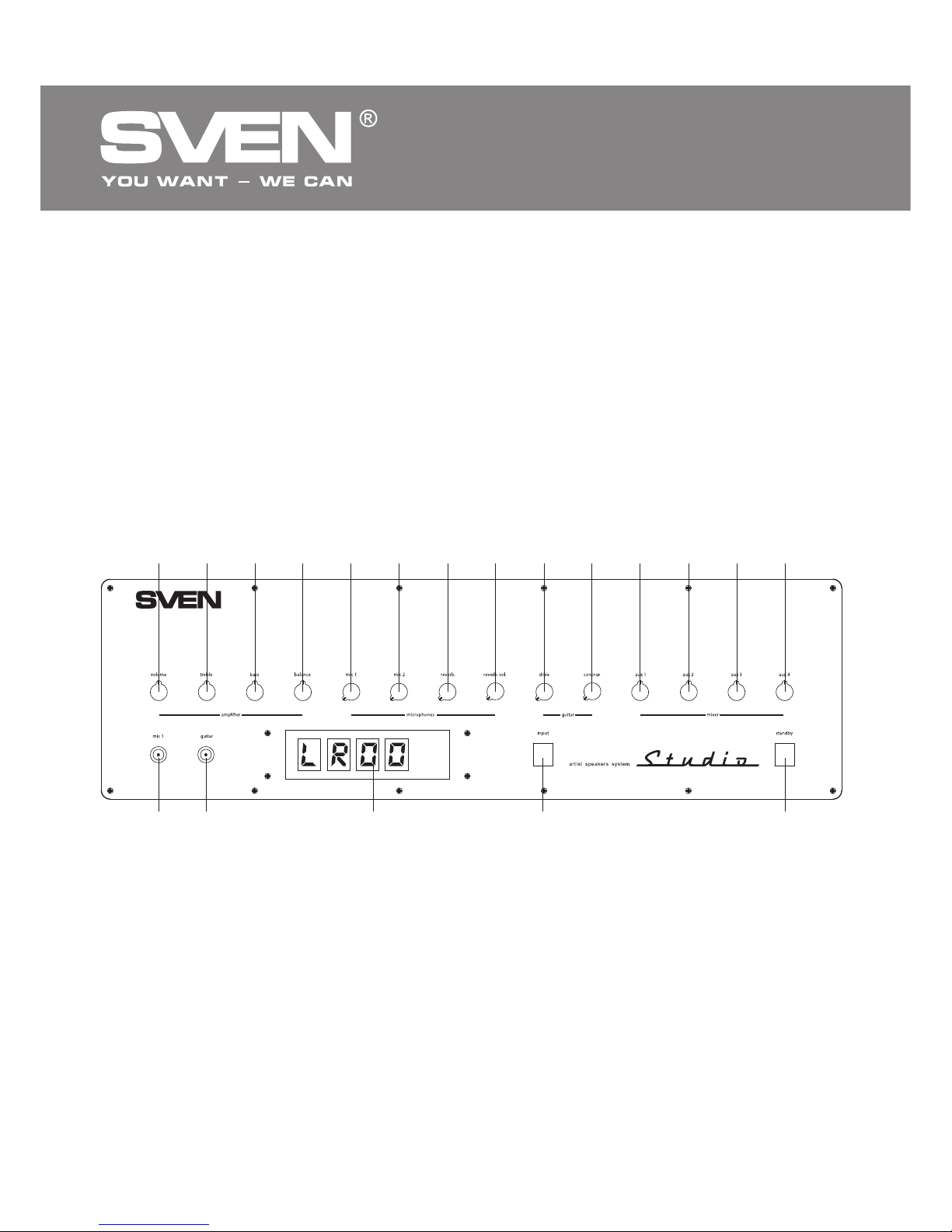
SPECIAL FEATURES
• Built-in dual-channel Hi-Fi power amplifier
• Two CD and PC stereo inputs, USB input, headphone jack, two microphone jacks, guitar
connection input, two mono inputs for connecting electronic musical instruments
• Horn tweeters with increased sound pressure
• LED display
• Built-in FM tuner
• Karaoke module with digital control
• Distortion effect module for electric guitars
• Full function remote control
• Master volume control and timbre control, headphone and microphone volume control,
reverberation level control
• High quality USB DAC for high fidelity sound transmission via a USB cable by connecting to PC
• High quality headphone amplifier
• Built-in high quality surge protector
• Carry handles
• MDF case of speakers
5. SPEAKER SYSTEM PLACEMENT
• Installation of STUDIO speaker system graded as Hi-Fi
(High Fidelity) class system is one of the most important
factors in achieving the best sound of the system. One
should know that location of speakers affects tonal
balance, intensity and quality of bass components, sound-
stage depth and width, midrange sounds transparency. On
the one hand, the closer the speakers are placed to walls
and corners, the more powerful the sound of the bass
components is. On the other hand, the farther the speakers
are located from walls, the better the soundstage depth is
rendered. Angular position and height of speakers’ location
in relation to the listener affect the timbral balance
formation (especially, treble), soundstage width, and
acoustic image focusing. Therefore speakers are best
located along the shorter wall of the room. The listener and
the speakers should be located in the corners of an
isosceles triangle as shown in the scheme, Fig.1 where
optimal Aand partial Bstereo effect zones are shaded.
Angular position and height of the speakers’ location in
relation to the listener should be defined by experiment.
The axes of the speakers should not intersect within the
area where the listeners are located.
Fig. 1. MSS location scheme
B
A