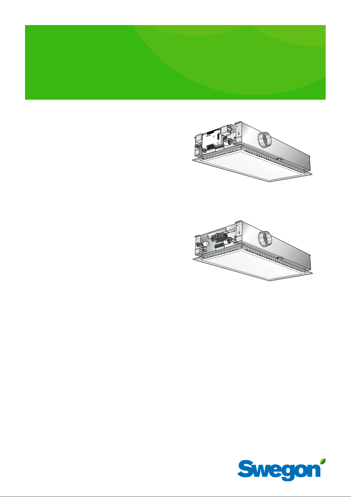
PARASOL VAV
10 Swegon reserves the right to alter specifications. 20160301
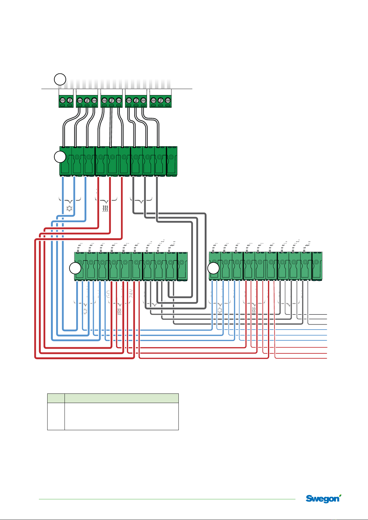
Conductor W4.1 VAV,
Commissioning/Checking the airflows
This information is a summary of the most important
points in connection with commissioning, checking the
airflows and adjustments.
For more detailed information see also Conductor
Technical Manual and Parasol VAV Product Datasheet at
swegon.com.
• Use CONTROL Zone dampers or equivalent dampers for
the best operation and constant pressurisation in the
zone.
• Check that all the products/constituent units are ener-
gised.
• Check that Conductor W4.1 VAV is set to Parasol VAV.
- Appl. parameter
- P_1964
- Value = 3
• Check that the Modbus address is correct if Super WISE
or another BMS is used.
- The Modbus address is unique for each room.
• For a correct Modbus addressing in the SuperWISE, the
room numbering is done in steps of 4.
Example
The master product in room no 1 shall have Modbus ID 4
The master product in room no 2 shall have Modbus ID 8
The master product in room no 3 shall have Modbus ID 12
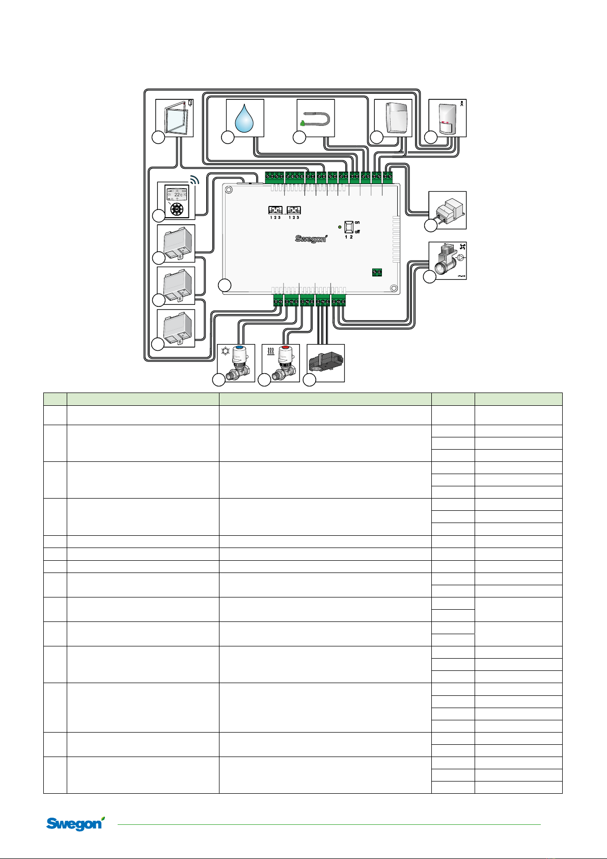
• Check the pressure sensor's address
- SA1 = 3
- SA2 = 6
-EA = 4 (optional: extra pressure sensor if the extract
air damper is controlled from Conductor)
To set the C-factors and airflows
The Conductor W4.1 VAV calculates how the air damper
should either open or close in order to obtain the required
airflow. The Conductor W4.1 VAV calculates the airflow
in the air duct on the basis of the C-factor (resistance) and
the pressure in each air duct.
The C-factor SA1 and SA2 respectively are the sum of
C-factor of SA1: long sides (side 2 + 4) and SA2: short
sides (side 1 + 3) for all the modules (Master and slave
modules) connected to a Conductor W4.1 VAV.
• Check and adjust, if required, the C-factors and airflows
• Ensure that the C-factors of the SA1 and SA2 and the
required airflows are correct:
- RE Settings
- C-factor SA1 = Enter the total C-factor for the long
sides.
- Norm SA1 = Enter room's required airflow for occu-
pancy.
- Boost SA1 = Enter the maximum airflow for the
room.
- C-factor SA2 = Enter the total C-factor for the short
sides.
- Boost, SA2, does not have to be changed since the
setting for SA1 is used even here.
+40°
-40°
0°
-40º +40º
0º
-40º 0º
0º
Vacancy flow
Conductor W4.1 VAV can also manage extract airflows.
Enter the vacancy flow as a percentage of the occupancy
flow (Norm SA1).
• Check and adjust the vacancy flow in menu P_1938.
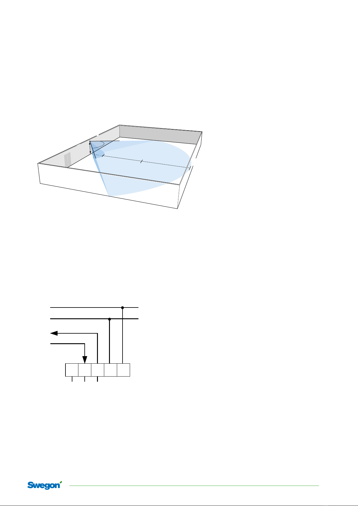
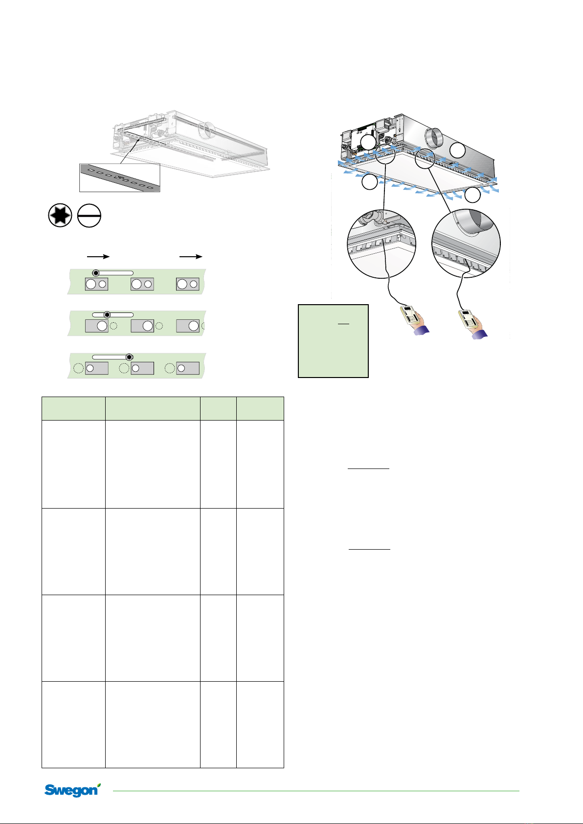
To check the performance of the actuators
• Check that the valve actuators for chilled water and
heated water are operating correctly.
- Settings - Commissioning – Water
- Activate and open the valve actuators with Cool
valve - Open or Heat valve – Open.
- Check after 2 - 3 minutes the actuator's indicator
which should now be in the raised position above
the enclosure which indicates that the actuator is in
the open position.
Commissioning and checking the airflows
Before you begin commissioning, ensure the following:
• The air handling unit has been started up
• The fire dampers, if required, are fully open
• The zone damper is in full operation
• Open the air damper of all the modules:
- Settings - Commissioning – Water
-Air – Max.Occ – On
The modules will now adjust themselves to product the
airflow that has been entered in Boost SA1.
• Check that the max. flow has been reached.
- Adjust the pressure setpoint of the zone dampers
upwards using the TUNE Control hand-held termi-
nal until the correct airflow has been obtained. If
the max. flow has still not been obtained, you can
close another/other zone damper(s).
The module (reference module) with the greatest devia-
tion from the design max. flow can be found by measur-
ing the max. flow of all the modules in the zone.