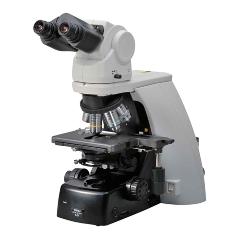
Nikon S-kt User manual

MICROSCOPEmodeI
S-Kt
INSTRUCTIO
NS
NIPPON
KOGAKUK.K.

I
1.
2.
CONTENTS
NOMENCLATURE
ATTACHINGTHELENSES .......6
(1) Mounting
the
Objectives.. 6
(2) MountingtheEyepieces
... l
(3) Mounting
the
Condenser
.. 7
ILLUMINATION .... 8
(1) CondenserlrisDiaphragm
.. g
3. (z
(3
(4
(5
(6
17
LightSource... g
Condenser
Focusing
Knob
. ; g
Brightness
Adjustment q
Preparation
andAdjustmentfor Observation f6
Observation
Photom
icrography
4.
(8) Filters
(9) llluminationforVeryLowMagnifications p
(10)
Replacingthe
Bulb . . n
FOCUSTNG . . ... 13
(1)
Focusins
nOiusireni........... ....13
(21 EyepieceAdjustment ....13
(3)
CoarseFocusing .......1a
tf
(41
PresetDevice ...14
(5)
FineFocusing ........14
(6)
Oillmmersion .....i........15
(Vl ExchangingStages . ..1b
MOVTNG
THESPECTMEN
ON
THE
STAGE ... ..
16
(1) RectangularMechanical
Stage
"R" ...
16
l2l Circular
GlidingStage
"C" ....
17
PHOTOMICROGRAPHY ....18
COMBINATIONS. ...19
(1) lnterchangeableEyepieceTubes ......20
(21
lnterchangeableStages ........20
OBJECTIVES,EYEPIECES,CONDENSERS ......21
(1) Objectives ......2i
(21 Eyepieces . ....29
(3) Combinationsof Objectivesand
Eyepieces .. 23
(4)
Condensers.. .....25
(5) llluminationSystem .....25
5.
6.
7.
8.
9. CAUTIONSINHANDLINGANDMAINTENANCE -27

I. NOMENCTATURE(]YIODEL
SBR.I{I)
E
yep
iece
Revolving
nosepiece
Objective
Stagelock screw
F
ield
lens
Voltmeter
window
Field
diaphragm
ring
Lamphousing
socket
Voltage
change-over
key
Filter
holderfor 33mm
diameterfilter
Condenser
focusing
knob
(range
2Bmm)
Field
diaphragm
centering
screw

fi=
Diopter
adjusting
rrng
Interpupillary
distanceadjusting
knob
(54-74mm)
Frrcnicectilhc clamn
Screw
Slide
holder
Condenser
clamP
Lock screw
for the condenser
diaph
ragmeccentering
lever
Condenser
diaph
ragmeccenteri
ng
leverfor oblique
illumination
Condenseririsdiaphragm
ring
Knob for longitudinaltravelof stage
Knob for lateraltravel
of stage
Coarse
focus
tensionadjusting
ring
Coarse
focus
knob (range
38mm)
F
ine
focus
knob
one
rotation0.2mm,
range38mm)
Brightness
adjusting
dial
Mainswitch
Coarse
focus
Preset
lever
Cordconnector
5

2. ATTAC]IINO
THTLENSTS
Before attaching the objective
and the
eyepieceto the microscope,
clean the
outer lenssurfaces.
Even a light finger
mark may often interfere with image
contrast.
(1) Mounting
the
Objectives
Take special care when handling the
objectives.
Beforeattaching
theobjectives
to the nosepiecerevolver, lower the
microscope
stage sufficiently. Securing
each objective with the fingers
of one
hand, screw it into eachnosepiece
hole
with thoseof the other hand (Fig.
3)
Microscope
model
S-Kt has
on the upper
srrrface of the noseniece
revolver
f
our
spots
indicated
@,
@),O and
O (Fig.
4) lt
is advisableto mount the objectives
below the indication
spot in order
from
lowto high
powers
as
below:
example
@
@
o.... 4xobjective
....10Xobjective
....40Xobjective
@.. . ...looxobjective
When rotating the revolver, hold the Fig'
4
outer milled rim with your thumb and
first finger. Do not push the objective
barrelsbecausealignmentof the objec-
tives
maV
bedisturbed
Fis.
3

(2)Mounting
the
Eyepieces
For mounting,simply
put theeyepiece
into theeyepiecetube.lt is
recommend-
edthattheeyepiecebeleft inplace
even
whennot in use
in orderto prevent
the
entrance
of dust into theeyepiecetube.
Or insert
theeyepiececap
inplace
of the
removed
eyepiece.The inclined
eyepiece
tube,
trinocular,binocular
gr monocular,
canbe rotated
after
looseningtheclamp
screw,
for convenience
in viewing
from
anvdesired
direction
withoutmoving
the
microscopestand.By further releasing
the clamp screw (Fig. 5) the eyepiece
tube canbe removed
and replaced
with
another
type.
(3)Mountingthe
Gondenser
To mountthecondenser,
loosenthe
lock
screw.and insert the condenser
from
beneath
thecondenser
holderas
farasit
will go.
Then,tighten
the
lock
screw.
In
this
case
locatethediaphragm
eccentering
lever
and its screw
at a convenient
posi-
tionsoas
to facilitatetheirmanipulation
with one hand (Fig. 6). The correct
distance
for retainingimmersion
oil be-
tween
the lowersurface
of theslide
and
the too of condenser
is obtained
when
thecondenser
israisedto theupper
limit
byturning
thecondenser
focus
knob.
Fis.5
Fis.6

3. ITTlJ]t|I]{ATION
Resolution
and
image
contrast
are
greatly
affected
bythe
illumination
method.
(1)
Condenser
lris
Diaphragm
Stopdown the condenser
iris
diaphragm
and slideit in a radial
direction
from
centerto edge.
The morethe iris dia-
phragm
isoff-center,
thehigher
thecon-
trastandresolution.
Details
of theobject
are
distinguished
byincreased
and
unsym-
metrical
shadows
atthe
boundaries
(Fig.
7,a,bl.
When
the irisdiaphragm
is
positioned
so
asto let
thelightbundleenter
theobject
at an angleof inc.idence
equalto the
apertureangleof theobjective,
thereso-
lutionreaches
themaximum
andtwice
as
muchastheresolution
by central
illumi-
natron.
lf thediaphragmisfurther
decenteredto
suchan extent
as
to prevent
the light
bundleentering
the objective,
oblique
darkfield illumination
will beobtained
(Fig.
7,c).lf theiris
diaphragm
isopened
wide,images
by illumination
at various
angles
are
obtained.
An illumination
angle
unfavorablefor the object may be in-
cl
uded.
In centralillumination
maximumresolu-
tionis
obtainedwhenthe
openingofthe
iris diaphragm
just corresponds
to the
apertureangleof the objective.
In this
case
excessiveouterrays
asused
fordark
field
illumination
arecutoff and
flare
is
minimized.lf the
opening
ismade
small-
er, contrastis enhanced,
althoughthe
resolution is lowered.
But if the iris
diaphragm is large enough to cover
60-700/0of the objective
aperture,the
decrease
of resolution
will not be pro-
nounceo.
lf thediaphragmis
stoppeddownto the
minimum
for admittingonlyvery
small
light
bundles,theeffects
of diffraction,
reflection,refraction,
etc., may be ex-
aggerated
so that fringes
may beseenat
the
image
edgeswhichmaylikely
induce
misinterpretationof the image,but it
(a)
Central
illumination (b) Obliqueillumination (c) Dark field illumination
Fig.7

may be effective
for special
occasions
(e.9.
definitionofthe
general
structureof
unstained
specimens).
(2)
LightSource
As already
discussed,
the irisdiaphragm
plays
an important
role
in illumination
for microscopy.
In principle,
the dia-
phragm
should
be so adjusted
that the
numericalaperture
of the condenser
is
equal
to thatof theobjectivebeing
used,
in order
to obtain
maximum
resolution.
ln practice,
however,
keeping
out stray
light
whlch
would
reduceimagecontrast
by closing
theaperture
of the
condenser
down to 60-700/o
of thatof theobjective
will bringabout good resultsin most
cases.
Thecoincidence
of condenser
dia-
phragm
aperture
with theaperture
(exit
pupil)
of theobjective
canbeascertained
by lookingdown the microscopetube
after
removingtheeyepieceand
closing
the diaphragm
slowly.
An experienced
user,
however,
may dispense
with this
procedure,
andobtain
thesame
resultby
adjusting
the diaphragm
opening
until
satisfactory
distinctness
of the image
is
obta
ined
.
lf high
resolutionand,atthesame
time,
high
contrastare
desirable,
oblique
illumi-
nation
maybe
effective.This
isespecially
suited
forlightlystainedspecimens,
trans-
Fig.I
parent phase
specimens,
etc. However,
withthis
illumination,
asharp
variation
in
contrast
and resolution
may appear;
it
may
benecessaryto change
thedirection
of illumination,
by turning
the
irisdia-
phragm.
The
condenser
aperture
maybedecenter-
ed
in
any
direction
by
rotating
and
atthe
same
time
radiallysliding
thediaphragm.
This
manipulation
canbe
doneby only
using
one hand,the thumb and first
finger
for decentering
and the middle
fingerfor opening
or closing
the dia-
phragm.
(See
Fig.8)
(3)
Condenser
Focusing
Knob
Condenser
focusing
is accomplished
by
turning
thecondenser
focusing
knob.
This
manipulation
isnecessary
mainly
for
Koehler
type illumination
or dark
field
observation.
The condenser
is usually
placed
attheupper
limitand
need
not
be
lowered.
(4)Brightness
Adjustment
Theconventional
method
ofadiusting
the
brightness
of the microscope
lamphas
been by a rheostat or transformer,
whereby the voltage
or amPerage
is
cnangeo.
Either method,however,
is disadvan-
tageous
in thattheformer
produces
heat
and the latter,
due to its largesize,
presents
difficulty
in mounting
it inthe
microscope
base.
Modern,advanced
semi-conductor
tech-
nologyhas
provided
a facility
forchang-
ingthe flow time of electric
means.A
so-called
thyristor
ofextremely
small
size
hasbeen
developed
to enable
regulation
of the
brightness
of the
lamp,The
Micro-
scope
Model
S-Kt
has
adopted
this
type
of lightadjuster
built in the
microscope

Dase.
Turnthe
brightnessad
justing
wheel
atthe
side
of the
base,andthe
green
area
in
the
voltmeter
windowwill indicate
thevolt-
age,
increasing
asthewheel
isturnedin
thedirectionofthe
arrowbelowit.
(5) Preparation and Adjustment for
Observation
O AttachingtheLamp
Cord
As shownin Fig.
9, insert
the cord
connector,facing
the notch
upward,
and fasten
it by a clockwise
turn of
theoutside
lockring.
@ Attaching
theLamp
Socket
The lampsocket
isattached
asfol-
lows:
Insert the socket,
fitting the key
groove
accordingto themarkinS
(FiS.
10).Turnit clockwise
and
push
it in
Since
the
socketwill automatically
be
positioned
by
friction,
thereis
no
need
forfurther
ad
justment.
Do not insert
the socket
fullv, but
leave
a clearance
of about2mm to
attainthe
brightestillumination.
O Centering
theRadiantField
Diaphragm
Usingthe 40X objective,
bringthe
specimen
into
sharp
focus.
Fully
close
the radiantfield
diaphragm.Move
the
condenser
lens vertically,
until a
sharply
focused
image
of the dia-
phragm
is obtained
on thespecimen
surface.Then, move
the diaphragm
imageto the center
by manipulating
thetwocentering
screws
(Fig.
11).
When
switchingto other objectives,
the diaphragmimage
may slightly
deviate
from the centered
position.
producing,
however,
no objectionable
resultsfor
routine
observation.
Fis.
9
Fig.10
Fig.
11
10

(6)Observation
Themicroscope
permits
observationwith
uniformly bright illuminationranging
from the 4X objectiveup to the oil-
immersion
100X
objective,
with no need
of changingtheillumination
system.
For
interference or phase-contrast
observa-
tion, turn the brightnessadjdsting
dial
(Fig.
12)
to
get
a
brighterimage
Notethat this
microscope
cannotbeused
for interference
phase-contrast
observa-
tion with the 100X oil-immersion,
be-
causeof insufficient
brightness.
It canbeused
with the40Xobjectivefor
up to a total magn
ificationof 400X,
when the illuminationls adiusted
for
maximum
brightness.
(7)Photomicrography
Comparedwith the NikonS-Ke
Micro-
scope,the
Model
S-Kt
will providephoto-
graphs
of somewhat
lower
contrast.
In monochromatic
photography,
good
contrast
can
be
obtained
by theuseof a
green
(monochrombtic)
filter.
In color
photomicrography.
asshownin
Fig. 13, the dial of the built-inlight
adjusterat the side
of the microscope
base
is to be set with the voltmeterin
PHOTO
position
(near
7.5V),where
the
green
area
fills
the
window.
UseNikonFilter
CBi65 orWratten58.
(8)Filters
Filters33mmin
diameter
areusedinthe
filter holder
beneaththecondenser
lens,
and 45mm diameterf
ilters abovethe
illuminationfield
lens.
Rri,rhtnocc :rlirrciino rl i:l
Fis.12
Fis.13

(9)llluminationforVeryLow
Magnifications
As shownin Fig. 14, usea low power
condenser
lens.Lower
thestage
to secure
a sharply
focused
imagein a uniformly
ilI
um
inatedviewfield.
In photomicrography,
for unlformly
brightillumination
wlthverylowmagnifi-
cations,
it is necessaryto movethe bulb
backand
forth.
(10)
Replacingthe
Bulb
First,
reverse
the attaching
procedure
to
removethe socket,andthen,whenthe
lampbulb
iscool,turn it inthedirection
opposite to the arrow mark on the
socket.
Insertthe
new
bulb
(6V
15W),as
shown
in Fig.15,
fitting
the
notchonthe
brim
ofthebulb
tothewhitecircle
found
on the foot of thearrow,and
rotatethe
lamp
socket
in thedirection
of thearrow
to instal
|.
/ Low power condenser ens
J\
Fig.
14
Fis.
15
12

4.
t0cljstilG
(1
) Focusing
Adjustment
Themodel
S-Ktis
provided
withcoaxial,
coarse
and fine focus knobs,
both of
which are loCated
nearthe base.
Clock-
wise
rotation
of either
of thefocusknobs
by the operator
lowersthe microscope
stageandviceversa
(Fig.
16,a,
b).
(2) Eyepiece
Adjustment
When using
a binocular
or trinocular
eyepiecetube
for observation,
theadjust-
ment of the user'seye-sight
(diopter)
discrepancy
between
the right and left
eyes
isnecessary.
Thisisdone
by rotating
the adjusting
ring on the lefthandeye-
piece
tube.
After focusing
with the right eye by
raisingor lowering
themicroscope
stage,
turn the adjusting
ring left or right to
obtain
asharp
image
withyourlefteye
as
well. Then, regulate
the interpupillary
distance
of thebinoculartubeby sliding
the eyepiecesleft or right by means
of
theknob
(Fig.
17),untiltheviewfieldsof
both eyepiecesmerge.lt will be advan-
tageousto memorize
theattaineddiopter
and interpupillary
distance
readingsfor
futureuse.
The reddot engraved
on the interpupil-
larydistance
scaleindicatesthe position
where the mechanical
tube lengthbe-
comesexactly
160mm.The HK (high
eyepointtype)eyepieces
have
aneyecup
on top,theextension
of whichwillgive
proper eye-to-lens
distance.
For those
who weareyeglasses,
the eyecup
should
be slipped
on to protectthe spectacle
tenses.
Fig.16,a
Fig.16,
b
Fig.17

(3)
Coarse
Focusing
The coarseadjustment
may be easedor
tightened
by meansof the coarse
focus
tension
adjusting
ring.
lf the
rotationof thecoarse
focus
knobis
too loose,turntheadjusting
ringcounter-
clockwise.
Too much 'tension
may be
adjusted
by turning
clockwise.
Excessive
rotation
intheoppositedirection
should
beavoided.
Never twist the focus knobs for this
adjustment
asin traditional
microscopes
whose
focus
knobs,coarseandfine,are
locatedseparately
(not
coaxial).
Focusing
may
be
performed
as
follows:First,
raise
the microscope
stage
until the distance
between
the specimen
andthe objective
becomes
lessthanthe
workingdistance
of
theobjective
tobeused
(See
tableon
p.21
and p.221
, then lookingthrough
the
eyepiece,lower the stage until the
specimen
to be examined
is clearlY
visible.
4X, 10X,40X and100X-objectives
are
parfocal,
andare
approximately
in focus
when revolvedinto positionone after
another. The use of the fine focus
knob
only isrequired
for critical
focus-
Ing.
(4)PresetDevice
The right-hand
focusknobhasa preset
leveronits
drum
(Fig.
18).
When the leveris fastenedby turning
clockwise
(as indicatedby the arrow)
until it stops,
the coarse
focus knobs
cannot be turned to move the stage
closerto the objective. This preset
is
utilized for quick refocusing
after the
stagehas been lowered and defocused
for changing
a specimen
or applying
immersion
oil. The preset
device,
when
locked,
prevents
damagingthe objective
and
glass
slide.
(5) Fine
Focusing
Manipulationof the
finefocus
knob
(Fig.
18)
is
necessary:
a. Toobtain
the
sharpest
image.
b. To transferthe focusfrom center
to
an
edgeofthe
viewfield.
c. To focusupon differentlayers
of a
thickspecimen.
d. To correct
aslight
blurring
which
may
occurwhenshifting
the
slide.
e. To measure
thethickness
of an
object
underexamination.
The microscope
issodesigned
that one
revolutionof the
fine
focusknob
raisesor
lowersthe
microscopestage
0.2mm.
This
permits
direct reading
on the left-hand
knob scale,
looking
from the front,to
0.002mm
(2ttm\.
The complete
range
of
f
ine
motion
is
38mm;
thesame
as
thatof
coarse
motion.
I
{
I
l
Fis.18
14

(6)
Oil
lmmersion
When
usingthe100X
objective,
theappli-
cation
of immersion
oil in the minute
space
(0.1-0.16mm)
between
theobjec-
tive and the cover
glass
is necessary
to
attain the specified
numerical
aperture.
Forcritical
workimmersion
oil
should
be
placed betweenthe top lens of the
condenser
and the slide
aswell as be-
tweenthe objective
andthe cover
glass.
Oil immersion
observation
is performed
as follows:
First,using
a 10X or 40X
objective
(dry system),
focusthe speci-
menandcenter
it inthe
viewfield.Set
the
preset
leverby turningclockwise.
Lower
the microscope
stage
and revolve
the
nosepiece
revolverto the'100X
objective.
After applying
a drop
of immersion
oil
onto thecover
glass,
raisethestage
to the
preset limit. Then focus by looking
through
theeyepiece
and
raisingthestage
carefully
by manipulating
thefine
focus
knob.The
oil immersion
100X
objective
isdesigned
to attainitscritical
focusby
about 1/3 forward rotationof the fine
focus
knob,that is,by bringing
thestage
about 0.08mm closer
to the objective
fromthe
parfocalposition.
Airbubbles
in
the
immersion
oil,
whichmaysometimes
spoil
the
microscope
image
andare
visible
whenlooking
into themicroscope
tube
withouttheeyepiece,
canbe
removed
by
repeating
slight
movements
of the nose-
piece
or by adding
a certain
quantity
of
immersion
oilorbv
meansofa
needle.
Unremoved hardened oil may often
impairthe image.
Therefore,
immediately
after finishing the work, removethe
remainingoil from thelens
usinga soft
cotton
clothmoistened
with xylol. Never
use
alcoholor immersethe front of the
objective
in xylol.
Becareful
not to useimmersion
oil that
has
been
agedand
thickened.
Therefractive
indexof theimmersion
oil
should
be1.515.
(7)ExchangingStages
Lower the stage
by meansof the coarse
focus knob and unlock the stage
lock
screw.
Thestage
can
thenbe
removed.
l
15

5. |||Ot|ING
THE
SPECIMEN
ON
T||E
STAGE
(1)Rectangular
Mechanical
Stage
ttRrt
This
stageenables
fine
crosswise
travelof
the slidein a range
of 50mm
x 75mm.
allowingreading
of the movement
to
O.imm by the useof the vernier
pro-
vided.
Forsecuring
theslide
inposition
on the
stage,
open
the
slideholder.
Each direction travel is performed
by
rotation
of twocoaxialknobs
located
one
above the other on the vertical rod
protruding
belowon the
left
sideviewed
from
the
front,
theupper
knob
being
for
longitudinal
and
thelower
one
for
lateral
travelof theslideonthe
stage
(Fig.
19).
Influorescence
microscopy
orwhen
using
oil immersion
objectives,
where
theclear-
ance
betweenthecondenser
andthe
slide
also
shouldbe
oil-immersed.
thickened
oil
maycause
irregular
travelofthe
slide.
In thiscase,removing
thecircular
open-
ing plateat the center
of the stageor
fastening
the
slide
holder
lock
screwwill
behelpfulfora
positive
travelof the
slide
(Fig.
20).Also,
theuseof thestage
with
spiral
grooves
is
recommended.
By loosening
thestagelock
screwon the
edgeof the
stage,thestage
canbe
rotated
horizontallyfor convenience
in observa-
tion from theopposite
sideof themicro-
scope
(Fig.21),
where
theeyepiece
tube
isrotated
180'.Thisrotation
of the
stage
may often be of use in photom
icro-
graphy,
when
the
picture
format
ischang-
ed from vertical
to horizontal
or vice
versa.lt is recommended
that the slide
adapteronthe
stage
(Fig.21)
beused
for
sufficient
longitudinal
travel
of the
slide
in
such
reversed
position.
Fig.
19
Slide holder lock screr"ry
Fig.2O
Fis.21
16

(2)
Circular
GlidingStage
"C"
The
circular
gliding
stage
(Fig.
22)
glides
and
rotates
smoothly
and
precisely
inany
desireddirection
within
acircleiSmm
in
diametersimply
by pushing
the rim of
the
stage
withones
f
ingers.
Tolockthe
gliding
stage
in
position.press
it downwardandturn
therimof the
stage
counterclockwise.
Fastening
of the glid-
ing stageis necessary
when using an
attachable
mechanicalstage(Fig. 23),
whichisavailableon
order.
Also
available
is the centerable
circular
rotating
stage
type G, which permits
measurementof
the rotating
angle
of specimen
with its
graduated
circular
scale
(Fig.
24).
Fis.22
Fig.23
Fig.24

6. P1|OTOillICROGRAP]|Y
TheMicroscope
Model
S-Kt,incorporat-
ing Koehlertype illumination
with the
light
sourcebuilt
inthe
microscope
base,
enables
convenient
andexcellent
photo-
micrography
by additionally
mounting
a
camera connected
to the microscope
eyepiece with a photom
icrograph
ic
adapter.
Therefore,
when
taking
photographs
of
the microscopic
imageon35mmfilm,
it
isrecommended
thattheNikonMicroflex
Model EFM (with built-in exposure
meter), AFM (with built-in exposure
meter permitting
automaticexposure
setting)
or PFM (manual
exposure
set-
ting) and the N
ikon F or Nikkormat
cameraor Nikon Dark Box M-35S
be
useo.
The importance
of photographic
record-
ing in modern m
icroscopy
being a
primary consideration,
the Microscope
Model S-Kt is rigidly constructed
to
accepta heavy
photographic
attachment
on top of the microscope
tubewith no
possibility of being affected by the
weight
or by vibration
due to shutter
operation.
For photomicrography,
the useof the
trinoculareyepiece
tube or the photo-
graphic
verticaleyepiece
tube is neces-
sary,
for directlymounting
the photo-
graphic
attachment.However,
theuse
of
the photographic
standwhich supports
the cameraindependently
and transfers
lessshuttervibration
t,tthemicroscope
is
preferable.
It isconvenient,
whenobserving
amoving
specimen
through
thebinoculartube,
to
usethe
trinoculartube,in
whichthelight
is
separatedbythehalf-reflecting
internal
prisms
andistransmitted
to theeyepiece
tubeandthe
camera.
lmportant
points
in photomicro-
graphy:
1.Avoid extraneouslight
coming
from
theoutside.
Setup the microscope
in a place
free
from vibration.
Usea vibration-proof
plate under the microscope,
if pos-
sible.
2. Carefully
adjustthe illumination
field
andaperture
diaphragms
for Koehler
type
illumination.
3. Photo-sensitive
film, has no accom-
modationfacility
such
asthehuman
eye.
Therefore,in photomicrography,
it is necessary
to adjust
the accom-
modation
of thefinder
to the
eve
to
seethecross-hairsinthefinder
sharply
at all times.
In otherwords,
focus
precisely
so that the image
of the
specimenand of the cross-hairsare
simultaneouslysharp,exceptwhen
usingthe
ground
glass
screen.
Forhigh
magnificationswith oil-immersion,
etc.,
thephotographic
stand,as
cited
above,is
specially
recommended.
For details on photomicrographic
methods,refer to the Instructionsfor
UsingtheNikonMicroflex
EFM,
AFMor
PFM
andother
manuals.
18

1. CO]||BINATIO}IS
The Nikon Microscope
Model S-Kt is
available
in various
combinations
with
different objectives, eyepieces,
con-
densers,
eyepiece
tubes,
andstages.For
example,Model SBR-Kt consists
of
Trinocular (45")
rinocular (30o)
with
Model
S microscope
standwith Koehler
type
built-inbase
illuminator.
Binocular
eyepiece
tube "8" and Bectangular
mechanical
stage
"R"
R
ectangu
lar
Mechan
ical
Circu
lar
Gliding
Fig.25
19
sm
3
so
rf
tI
.,-._
/-
-.
I rti'Fr
$0
aduated,
Rotatable
Vertical
Photo @(3oo)

(1
) InterchangeableEyepiece
Tubes
a "U" Trinocular
Magnificationfactor
1X.Has
provision
for
dioptercompensationand
interpupillary
distanceadjustmentfrom 54mmto 74mm.
Observation
binocularsinclined45o,
phototube
upright,360o rotatable.With built-in
sliding
prism
system,
light
transmission
can be switched
threewaysto permit photomicrography
through
verticaltubewhileviewing
throughbinoculartube;i00% of lightdirected
to
observationbinoculars
by switching
light path or total lightdirected
to vertical
photo
tube
for photomicrography,
micro-projection
or closed-circuit
T.V.
pickup.
. "F" Trinocular
Magnificationfactor 1.25X.2-way sliding
prism;lOOo/oof light directedto
observationbinocularsortotallight
directed
to vertical
photo
tubefor photomicro-
graphy.
Inclined
30o
from horizontal
and
rotatable
360o.
Has
provision
fordiopter
compensation.Interpupillarydistance
adjustment
from
54mm
to74rnm.
. "8" Binocular
Magnif
icationfactor
1X.
Inclined
45oand
rotatable
360o.
Has
provision
fordiopter
compensation.Interpupillarydistance
adjustment
from
54mm
to74mm.
. "Y" Binocular
Magnificationfactor
i.25X. Inclined
30o
fromhorizontaland
rotatable
360o.
Has
provision
for
dioptercompensation.Interpupillarydistanceadjustment
from
54mm
to74mm.
. "A" InclinedMonocularwithVertical
Photo
Tube
Magnificationfactor
1X.Observationmonocularinclined30"
from
horizontal,and
photo
tubeupright,
360"
rotatable,
withbuilt-in,2waysliding
prism.
lnclined
Monocular
Magnification
factor
1X.
Inclined
45oand
rotatable
360o
(2)lnterchangeable
Stages
o "R" Rectangular
Medranical
Stagesurface130mmx 140mm.
Haslow-positioned
coaxial
X and Y motion
controlswhich provide
exceptionallyfine, smooth
crosstravelwithin rangeof
50mmx 75mm.
Scales
graduated
to0.1mmonvernier.
. "C" Circular
Gliding
Stagesurface140mmin diameter.
Provided
with stage
clips.Acceptsattachable
mechanical
stageavailableonorder.Moves
smoothly
inanydirection
withincircle
diameterof 18mmin straightand/or
rotatingmotion.
Canbeclamped
in any
desired
position.
. "G" Graduated,
Circular
Rotatable
Stagesurface
140mm
in diameter.360o
rotatable.
Goniometer
dividedinto 1o
increments
and
reads
to 6'with vernier.Centerable
stage
provided
withclamping
screw.Suppliedwithstageclips.
. "P" Sguare
Plain
Stagesurfacei30mm x 130mm.Provided
with stage
clips.Acceptsattachable
mechanical
stageavailableonorder. 20

8.
(1)
Objectives
o Forbiological
andmedical
use
(For
general
observation)
EYEPIECES,
CONDENSERS
OBJTCTIt|ES,
Table 1
Type
4X 0.10 28.3 9.50
14.8 7.10
Dry No cover
glass
type
Spring-loaded
Dry Ptan rox -l.is 15.6 7.o
[Orv -' prun 2OX O.4O 7.5 1.6 Spring-loaded
!otv_=_ llql 1!l_ 0.65 4.o _ 0.24_ qrr1o-loaded
rtrv ptrn NC4n)( n Aq ? R 't
? No cover
glass
type,
Dry Plan NC40X 0.65 3.8 1.3 Sor.s:i"#"j
Oif-immersion
Plan 100X 1.30 1.6 O.12 Spring-loaded
Oif-immersion Fl 7OX 1.25 2.5 0.16 Sorinq,loaded
D:t l{ Plul aor _ !.75 9j_0r45_ _
Sprins-loaded
Oil-immersion F/ Plan '100X 1.30 'l
.6 O.12 Spring-loaded
Apo 40X 0.80 4.3 0.19 Spring-loaded
Apochromat t ^.:-
ult-rmmersron Apo '100X 1.40 1.7 0.10 Spring
loaded
(For
special
observation)
Individual
Magnification Numerical
Aperture
Dry
, Dw 2OX
Achromat , Dry S40X
Oil-immsrsion Spring-loaded
oil.immersion 100x 1
.25 1.g 0.16 Withirisdiaphragmfor
dark-field
Dry Plan l.2X O.O3 35.8 2g.l
Dry Plan 2X 0.05 42.3 35.6
Dry Plan 3X 0.08 37.7 28.6
Dry Plan 4X 0.1O 2g.5 '18.2
Plan
Achromat
Table
2
Type Individual
Magnification
LWD4OX
WlOX
W2OX
W40X 0.65 4.4
^,..-^-,^^,
' Focal lworfing I
'ifiijjii' t-,""et1'
Distanc-e Remarks
' tmm, tmm,
0.60
o.22
0.33
4.O
16.0
7.7
2.O For tissue
cultureobservation,
spri
ng-l
oaded
0 - Water-immersionobjective
Achromat
l
2.O Spring-loaded
0 - Water-immersion
objective,
2.O Spring-loaded
^ 1A Water-immersionobjective,
Sp
rinq-loaded
The obiectives are designed to give the above magnifying powers with the best definition, when used
with a microscope whose tube length is 'l6Omm.
Basides the magniJying power, the numerical aperture or angular aperture of the light cone admitted
into the objective isalso an important consideration, as it largely determines the resolution or def ining
power, depth of focus and the brightness of the microscope image.
All the above obiectives
are
parfocal within the fine focusing range.
For AOx objectives, a cover glass (O.1
7mm thick) must be used. In casethe cover glass
is unusable, use
an NC 40x objective.
Length Distance i
Fluorite
21
Table of contents
Other Nikon Microscope manuals

Nikon
Nikon 50i User manual

Nikon
Nikon LABOPHOT-POL User manual

Nikon
Nikon eclipse Ci-S User manual

Nikon
Nikon Eclipse Ti TIFT 1454 User manual

Nikon
Nikon Eclipse E400 POL User manual

Nikon
Nikon A1+ Manual

Nikon
Nikon ECLIPSE E200 POL User manual

Nikon
Nikon coolscope User manual

Nikon
Nikon Eclipse E400 POL User manual

Nikon
Nikon Eclipse E600W User manual

Nikon
Nikon Optiphot User manual

Nikon
Nikon SMZ1500 User manual

Nikon
Nikon Eclipse 50i POL User manual

Nikon
Nikon N-STORM User manual

Nikon
Nikon Eclipse E600 User manual

Nikon
Nikon Multizoom AZ100 Release Note

Nikon
Nikon E800 User manual

Nikon
Nikon SMZ-U User manual

Nikon
Nikon Optiphot Operating instructions

Nikon
Nikon Eclipse TS100 User manual