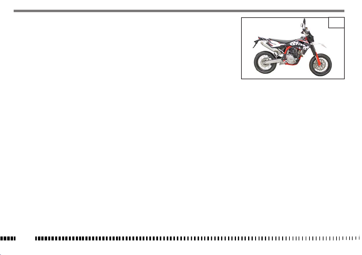
SWM SM 500R User manual

SM 500R
Manual - Operation - Maintenance

SM
EN - 2
PRESENTATION
Welcome to the SWM motorcycling Family!
Your new SWM motorcycle is designed and manu-
factured to be the best in its field.
The instructions in this book have been prepared
to provide a simple and understandable guide for
your motorcycle’s operation and care.
Follow the instructions carefully to obtain maxi-
mum performance and your personal motorcycling
pleasure. Your owner’s manual contains instruc-
tions for owner care and maintenance.
The main repair or maintenance work requires the
attention of a skilled mechanic and the use of spe-
cial tools and equipment.
Your SWM Dealer has the facilities, experience and
original parts necessary to properly render this
valuable service.
This “Owner’s Manual” is part and parcel of
the motorcycle, hence, it shall remain with
the motorcycle even when sold to another
user.
This motorcycle uses components designed thanks
to systems and state-of-the-art technologies
which are thereafter tested in competitions.
In racing motorcycles, every detail is verified after
each race in order to always guarantee better per-
formance.
To ensure trouble-free operation of the vehicle, it is
necessary to follow the maintenance and inspec-
tion table found under Appendix A.
IMPORTANT NOTICES
1) SM models are STREET LEGAL motorcycles; they
are guaranteed exempt from functional defects
and covered with legal guarantee, as far as the
STANDARD CONFIGURATION IS MAINTAINED and the
suggested maintenance table, shown in Appendix
A, is observed.
2) All the motorcycles and any of their parts
used in competitions of any type are excluded
from the warranty.

EN
EN - 3
Parts Replacement
When parts replacement is required, use only SWM
ORIGINAL parts.
WARNING*: After a crash, inspect the motor-
cycle carefully. Make sure that the throttle,
brake, clutch and all other systems are un-
damaged. Riding with a damaged motorcycle
can lead to a serious accident.
WARNING*: Never attempt to start or operate
your motorcycle unless you are wearing ap-
propriate protective clothing. Always wear a
motorcycle helmet, boots, gloves, goggles and
other appropriate protective clothing.
IMPORTANT
In order to maintain the vehicle’s “Guarantee
of Functionality”, the client must follow the
maintenance programme indicated in the
user’s manual by carrying out maintenance
inspections at authorised SWM dealers.
The cost for changing parts and for the labour
necessary in order to comply with the mainte-
nance plan is charged to the Client.
Note*: the warranty is NULL AND VOID if the
motorcycle is rented.
Important Notice
Read this manual carefully and pay special attention
to statements preceded by the following words:
WARNING*: Indicates the possibility of severe
personal injury or death if instructions are not
followed.
CAUTION*: Indicates the possibility of personal
injury or vehicle damage if instructions are
not followed.
Note*: Gives helpful information.
WARNING*:
• Park the vehicle where it is unlikely to be
bumped into or damaged.
Even slight or involuntary bumps can cause
the vehicle to tip over, with subsequent risk
of serious harm to people or children.
• To prevent the vehicle from tipping over,
never park it on soft or uneven ground, nor
on asphalt strongly heated by the sun.
• Engineandexhaustpipesbecomeveryhot
during riding. Always park your motorcy-
cle where people or children can not easily
reach these parts, in order to avoid serious
scalds.

EN - 4
SAFE RIDING AND MOTORCYCLE SAFETY
Here are some basic principles for riding your mo-
torcycle safely.
- Remember that your safety and the safety of
your passenger come rst. Reaching your desti-
nation safely must be your main aim.
- The rider and the passenger must wear appropri-
ate protective clothing, such as suit, gloves, shoes
and helmet homologated for motorcycle use..
- The rider must be seated on the motorcycle in a
position that gives the best possible visibility of
the road ahead.
- Ride the motorcycle carefully and set the speed
according to trac and the type of road.
Smooth riding helps you to assess danger and en-
ter bends more precisely.
- Always observe road signs and adjust your speed
accordingly.
- Always observe speed limits.
- Always assess the road conditions and adjust
your speed accordingly.
- Reduce speed if it is raining and especially if there
are puddles of water on the road.
- When riding on wet or low grip surfaces (snow,
ice, mud, etc.) keep a moderate speed and avoid
sudden braking and manoeuvres.
- Keep a safe distance from the vehicles in front of
you.
- Before overtaking, check there are no obstacles
in front of the vehicle you want to overtake and
always check in the rear-view mirrors that there
are no vehicles coming up from behind.
- Brake using both the front and the rear brake at
the same time: this helps to maintain the stability
of the vehicle.
- Release the clutch gradually when downshifting.
- If you feel tired or sleepy, take a break.
- Downshift in the following instances:
When going downhill and when braking to in-
crease the braking action through engine com-
pression; using only brakes when going downhill
could cause the brake pads to overheat and re-
duce the braking action;
When going uphill or on the at when the gear
does not match the speed of the motorcycle (high
gear and low speed);

EN
EN - 5
WARNING*: Downshift one gear at a time;
downshifting more than one gear at a time
may cause the engine to overrev and/or block
the rear wheel.
- Do not switch o the engine when going downhill.
- When you ride with a passenger, increase the dis-
tance from the vehicles in front of you and bar in
mind your weight when you brake and when you
have to round a bend or overtake.
- The riding position of both the rider and the pas-
senger is important for motorcycle control.
- While riding, the rider must keep both hands on
the handlebar and both feet on the footrests in
order to keep the motorcycle under control.
- The passenger must always hold on to the rider
or the passenger handle with both hands and
keep both feet on the passenger footrests. Never
carry a passenger that is unable to rmly place
both feet on the passenger footrests.
- Never ride under the inuence of alcohol or drugs.
- This motorcycle is designed exclusively for road
use. It is not suitable for o-road use.
Risks related to carbon monoxide
Exhaust gas contains carbon monoxide, a colourless
and odourless gas. Breathing in carbon monoxide
may cause loss of consciousness and death.
If you start the engine in a fully or partially closed
environment, the air you breathe in may contain a
hazardous amount of carbon monoxide. Never start
the motorcycle in a garage or other closed places.
WARNING*:
Carbon monoxide is a toxic gas.
Breathing in carbon monoxide may cause loss
of consciousness and death.
Avoid any areas or activities where you may
be exposed to carbon monoxide.

EN - 6
SUMMARY Page
PRESENTATION.......................................................................... 2
IMPORTANT NOTICES ............................................................ 2
IDENTIFICATION DATA ........................................................... 7
CONTROLS LOCATION ............................................................8
TECHNICAL DATA .....................................................................9
TABLE FOR LUBRICATION, SUPPLIES ..............................10
CONTROLS...................................................................................11
RIDING .........................................................................................21
ELECTRICAL COMPONENTS LOCATION..........................59
EQUIPMENT...............................................................................67
APPENDIX..................................................................................68
PRE-DELIVERY INSPECTION ............................................... 69
ALPHABETICAL INDEX ..........................................................70
SCHEDULED MAINTENANCE.......................... APPENDIX A
Note
• References to the “left” or “right” of the motor-
cycle are considered from the point of view of a
person facing forward.
• Z: number of teeth
• A: Austria
AUS: Australia
B: Belgium
BR: Brazil
CDN: Canada
CH: Switzerland
D: Germany
E: Spain
F: France
FIN: Finland
GB: Great Britain
I: Italy
J: Japan
USA: United States of America
• Unless otherwise specified, all the data and the
instructions are referred to any and all Countries.

1
2
*ZN0B600AAKV000000*
(
l
) (▲)(
♦
)
EN
EN - 7
IDENTIFICATION DATA
The engine identification number is stamped at the
top of the crankcase, while vehicle serial number
or Vehicle Identification Number is stamped on the
steering head tube.
Always quote the number stamped on the
frame when ordering spare parts or requesting
further details about your vehicle and note it on this
booklet.
CHASSIS NUMBER
VEHICLE IDENTIFICATION NUMBER (V.I.N.)
The full 17-digit serial, or Vehicle Identification Num-
ber, is stamped on the steering tube (R.H. side).
(
l
) = Model designation
(
▲
) = Model Year (2018)
(
♦
) = Progressive no.
1. Chassis serial number
2. Engine serial number

2
56
1
3
4
7
9
8
EN - 8
CONTROLS LOCATION
1. Front brake lever
2. Throttle grip
3. Rear brake control pedal
4. Right handlebar switch
5. Digital instrument
6. Ignition switch
7. Left handlebar switch
8. Clutch control lever
9. Gearbox control pedal (to engage first gear, push
the lever down, for other gears push it upwards.
The “idle” gear is between the first and second
gear).

EN
EN - 9
TECHNICAL DATA
ENGINE
Type .....................single cylinder, 4 stroke
Cooling liquid with electric fan
Bore .....................................3.81 in.
Stroke ..................................2.67 in.
Displacement ........................ 30.56 cu. in
Compression ratio..........................12,9:1
Starting .................................electric
(with automatic decompressor)
TIMING SYSTEM
Type ..........double overhead camshaft; 4 valve
Valve clearance (with engine cold)
Intake..........................0.004 ÷ 0,006 in.
Exhaust ........................0.007 ÷ 0,009 in.
LUBRICATION
Type ................Dry sump with two oil pump
rotor and cartridge filter
IGNITION
Type ..............Electronic, inductive discharge,
with adjustable advance (digital control)
Spark plug type........................NGK CR8E
Spark plug gap .........................0.027 in.
FUEL SYSTEM
Type .....................Electronic injection feed
PRIMARY DRIVE
Drive pinion gear- Clutch ring gear.......Z 23- Z 63
Transmission ratio .........................2,739
CLUTCH
Type .................oil bath multiple disc clutch,
hydraulic control
TRANSMISSION
Type ...................constant mesh gear type
Transmission ratio
1st gear ..........................2,000 (z 28/14)
2nd gear ...........................1,611 (z 29/18)
3rd gear...........................1,333 (z 24/18)
4th gear..........................1,086 (z 25/23)
5 th gear .........................0,920 (z 23/25)
6 th gear ..........................0,814 (z 22/27)
SECONDARY DRIVE
Transmission sprocket-
Rear wheel sprocket....................Z 15- Z 42
Transmission ratio .........................2,800
FRAME
Type .... single beam, double cradle in steel tubes;
rear frame in light alloy.
FRONT SUSPENSION
Type .........”Upside-down” telescopic hydraulic
front fork with advanced axle
(adjustable in compression and
rebound stroke); stanchions tubes Ø 1.89 in.
Legs axis stroke .........................9,84 in.
REAR SUSPENSION
Type ............progressive with hydraulic single
shock absorber (adjustable in compression
and rebound stroke)
Wheel stroke .............................11,41 in.
FRONT BRAKE
Type ....................floating disc Ø 12.59 mm
“Wave” type with hydraulic control
and fixed radial caliper
REAR BRAKE
Type ....................fixed disc, ø 9.45 in. with
hydraulic control and floating caliper
RIMS
Front.......................in light alloy: 3,50x17”
Rear ........................in light alloy 4,25x17”

EN - 10
TIRES
Front.................................120/70-17”
Rear .................................150/60x17”
COLD TYRE PRESSURE
Rider only
Front ....................................2.0 psi
Rear .....................................2.2 psi
Rider and passenger
Front.....................................2.2 psi
Rear .....................................2.4 psi
DIMENSION, WEIGHT, CAPACITY
Wheelbase .............................57.68 in.
Overall length............................83.15 in.
Overall width ...........................32.30 in.
Overall height...........................48.03 in.
Saddle height............................37.01 in.
Minimum ground clearance ...............11.73 in.
Dry weight .............................lb. 293.21
Fuel tank capacity (1.58 Imp. Qt./ 1.9 U.S. Qt.
reserve included) .......1.58 Imp. Gall./ 1.9 U.S. Gall
Coolant capacity ...............2.0÷2.4 Imp. Pints;
2.3÷2.7 U.S. Pints
Transmission oil
Oil and oil filter replacement Imp. Quarts 1.5,
U.S. Quarts 1.8
Oil replacement ...................Imp. Quarts 1.3,
U.S. Quarts 1.6
TABLE FOR LUBRICATION, SUPPLIES
Engine, gearbox and primary drive lubricating oil
MOTUL 7100 TECHNOSYNTHESE 5W40
Engine coolant
MOTUL MOTOCOOL EXPERT
Brake system fluid
MOTUL DOT 3&4
Clutch fluid
SAE 10 MINERAL OIL FOR HYDRAULIC CIRCUITS
Grease lubrication
MOTUL GREASE 100
Final drive chain lubrication
MOTUL CHAIN LUBE
Front fork oil
MOTUL FORK OIL LIGHT 5W
Oil for rear shock absorber
MOTUL MOTUL SHOCK OIL FL
Electric contact protection
MOTUL EZ LUBE

1
1
2
EN
EN - 11
CONTROLS
FUEL
Recommended fuel: premium grade UNLEADED fuel
(R.O.N. 98).
WARNING*: Do not continue operation if the
engine pings or knocks.The engine will be
damaged and could seize.
WARNING*: Fuel is extremely flammable and
can be explosive under certain conditions.
Always stop the engine and do not smoke or
allow flames or sparks in the area where the
motorcycle is refuelled or fuel is stored.
WARNING*: Do not overfill the tank. Refer to
the lower mark on filler. After refuelling,
make sure the tank cap (1) is closed securely.
SIDESTAND
A kickstand (1) is supplied with every motorcycle.
WARNING*: The stand is designed to support
the weight of the MOTORCYCLE ONLY. Do not
sit on the motorcycle using the stand for sup-
port as this could cause structural failure to
the stand and could cause serious bodily in-
jury.
WARNING*:
The motorcycle must ONLY be stood on its
kickstand AFTER the rider has dismounted.
Once the motorbike has been brought from
its rest position on the ground into vertical po-
sition, the driver has to raise the stand from
the lowered to the raised position with his left
foot.
WARNING*: A safety sensor (2) is fitted on the
motorbike, which allows starting it with the
stand lowered and the gear in neutral.
If a gear is engaged with the stand lowered,
the engine turns off.

4
5
21
3
A
EN - 12
DIGITAL INSTRUMENT, WARNING LIGHTS
The motorcycle is equipped with a digital instru-
ment with 5 indicator lights: high-beam headlight,
engine malfunction, direction indicators, neutral,
and ABS.
1) High-beam light (BLUE).
Turns on when the low-beam headlights are acti-
vated.
2) Engine malfunction indicator light (ORANGE).
Turns on when the engine is not functioning prop-
erly; in this case, it is recommended to visit an
SWM service centre as soon as possible.
The indicator light turns o once the malfunction
has been resolved.
3) Turning indicator light (GREEN).
Starts ashing when the right or left direction in-
dicator is activated.
4) Neutral warning light (GREEN).
Turns on when the gear shift lever is in the neutral
position.
5) ABS warning light ABS (ORANGE).
Starts ashing when the rear wheel’s ABS func-
tion is deactivated.
Remains on if an ABS system malfunction is de-
tected; in this case, it is recommended to visit an
SWM service centre as soon as possible.
The indicator light turns o once the malfunction
has been resolved.
NOTE:
- The display check will be carried out for the first
few seconds after turning the key; once the check
phase has been completed, the instrument will
display the last function set.
- When the engine is turned o, the instrument
does not show any functions.
- To select instrument functions and reset func-
tions, use the SCROLL button (A)
- The functions, which can be selected in order are
as follows:
1- SPEED / ODO / FUEL
2- SPEED / H / FUEL
3- SPEED / CLOCK / FUEL
4- SPEED / TRIP 1 / FUEL
5- SPEED / STP 1 / FUEL
6- SPEED / AVS 1 / FUEL
7- SPEED / SPEED MAX / FUEL
8- SPEED / TRIP 2 / FUEL
9- TRP 2 / CLOCK / FUEL
10- SPEED / RPM (engine r.p.m. numerical value) /
FUEL
.................

1
12
EN
EN - 13
RESERVE FUEL LEVEL INDICATOR
When the fuel inside the tank reaches the reserve
level, bar (1), will begin flashing; in this case, it is
recommended to refuel as soon as possible.
1- SPEED (kmh or mph) / ODO / FUEL
(figure 1)
- SPEED: 299 kmh or 299 mph;
- ODO: odometer- maximum value: 99999 km;
To replace kilometers with miles or miles with kilom-
eters proceed as follows:
1) set to gure 1, place the ignition key in the OFF
position and push the knob SCROLL (A);
2) place the ignition key in the ON position while
pressing the SCROLL wheel for 3 seconds (A)
To confirm the conversion, the “SET” and the Miles
and mph or km and kmh segment will activate for
3 seconds; afterwards the standard function in Fig.1
will reappear.
NOTE
After the previously described operation, the
ODO setting will be converted and all other
data reset (the H Counteris unchanged).
2- SPEED / H / FUEL (figure 2)
- SPEED: 299 kmh or 299 mph;
- H: shows the running hours of the engine (data
are saved in permanent memory every 10 min-
utes). Maximum value: 9999:59.

3 4 5
EN - 14
3- SPEED / CLOCK / FUEL (figure 3)
- SPEED: 299 kmh or 299mph;
- CLOCK: Clock- reading from 0:00 to 23:59:59 (the
data will be lost after detaching battery);
To set clock, press the SCROLL button (A) for 3 sec-
onds or more to increase the hour; release button
and after 3 seconds the minutes can be increased.
4- SPEED / TRIP 1 / FUEL (figure 4)
- SPEED: 299 kmh or 299mph;
- TRIP 1: distance- maximum value: 999.9 km (the
data will be lost after detaching battery).
If the STP 1 is set to zero, the functions TRIP 1 and
AVS1 will also be set to zero.
The function TRIP 1 is ON together with the
function STP 1 (*).
(*): see gure 5
5- SPEED / STP 1 / FUEL (figure 5)
- SPEED: 299 kmh or 299mph;
- STP 1: miles/kilometers covered time
- Reading from 0:00 to 23:59:59 (the data will be
lost after detaching battery).
To activate the function STP 1, push the knob SCROLL
(A) for more than 3 seconds.
- 1st step: function ON;
- 2nd step: stop counters;
- 3rd step: reset STP 1, TRIP and AVS 1 data;
- 4th step: activate function;
- 5th step: stop counters
.............................
and so on
NOTE
STP 1 data + TRIP 1 data = AVS 1 (*).
(*): see figure 6

6 7 8
A
EN
EN - 15
6- SPEED / AVS 1 / FUEL (figure 6)
- SPEED: 299 kmh or 299 mph;
- AVS 1: shows the average speed for vehicle cov-
erage, distance data (TRIP 1) and covered time
(STP1) (the data will be lost after detaching bat-
tery).
NOTE
Resetting the STP 1 also resets the TRIP 1 and AVS
1 data.
7- SPEED / V MAX / FUEL (figure 7)
- SPEED: m 299 kmh or 299 mph;
- V MAX: Shows the maximum speed reached by
the vehicle, in kmh or mph.
Maximum value: 299 kmh or 299 mph. To set to zero
V MAX, push the knob SCROLL (A) for more than 3
seconds.
8- SPEED / TRIP 2 / FUEL (figure 8)
- SPEED: 299 kmh or 299 mph;
- TRIP 2: distance- maximum value: 999.9 km/
miles (the data will be lost after detaching bat-
tery);
To set TRIP 2 to zero, push the knob SCROLL (A) for
more than 3 seconds.

910
EN - 16
9- TRP 2 / CLOCK / FUEL (figure 9)
- TRIP 2: distance- Max value: 999.9 km / miles
(the data will be lost after detaching battery).
To set TRIP 2 to zero, push the knob SCROLL (A) for
more than 3 seconds;
- CLOCK: Clock-reading from 0:00 to 23:59:59 (the
data will be lost after detaching battery).
To reset the clock, push the knob SCROLL (A) for
more than 3 seconds in order to increase the hours;
release the knob then, after 3 seconds, it is possible
to increase the minutes.
10- SPEED /RPM / FUEL (engine r.p.m. numeri-
cal value) (figure 10)
- SPEED: 299 kmh or 299 mph.

1
3
1
4
2
EN
EN - 17
THROTTLE CONTROL
The throttle twistgrip (1) is located on the right-hand
side of the handlebar. The position of the throttle
control can be adjusted by loosening the two retain-
ing screws (2).
CAUTION*: Do not forget to tighten the screws
(2) after the adjustment.
FRONT BRAKE CONTROL
The brake control lever (3) is located on the right-
hand side of the handlebar. The position of the
throttle control can be adjusted by loosening the
two retaining screws (4).
CAUTION*: Do not forget to tighten the screws
(4) after the adjustment.
IGNITION SWITCH
The ignition switch has two positions:
motorcycle start position (key not removable)
key removal position
- Key removal position
Turning the key to position , the engine and
the lights go o and you can remove the key from
the ignition block.
- Start position
From the key removal position , turn the key
(1) clockwise to the start position ; the lights
and the display will come and you can start the
motorcycle.

2
1
1
EN - 18
STEERING LOCK
The motorcycle is equipped with a steering lock (1)
on the R.H. side of the steering head tube.
To lock it, procede as follows:
turn the handlebar leftwards, place the key in lock
and turn counterclockwise. Push the key inwards (if
necessary, turn to and from). Turn the key clockwise
and remove it from the lock.
To unlock the steering lock, reverse the above pro-
cedure.
WARNING*: Do not turn the handlebar while
the key is in the steering lock, to avoid break-
ing the key.
R.H. HANDLEBAR SWITCH
The right-hand switch features the following con-
trols:
1) Engine start button
2) Engine KILL SWITCH.

1
2
3
4
5
A
B
C C
B
EN
EN - 19
LEFT HAND HANDLEBAR SWITCH
The left hand handlebar switch contains the follow-
ing commands:
Headlamp (A)
1) High beam flasher (automatic turn-off)
2) High beam switch
Low beam switch
Indicators (turning signals) (B), (C)
3) Left turn indicator
Right turn indicator
To deactivate the indicators, press the control level
after it has returned to centre.
4) Horn
5) Rear wheel ABS exclusion selector
- The ABS function on the rear wheel can be deac-
tivated for circuit riding.
NOTE
In order to activate or deactivate the ABS func-
tion on the rear wheel, the motorcycle must be
stationary.
Rear wheel ABS deactivation
- To deactivate the ABS function on the rear wheel,
move the selector (5) towards “ ” and hold it
there for 3 seconds; the “ ABS ” indicator light on
the digital instrument will begin flashing.
Rear wheel ABS activation
- To reactivate the ABS function, move the selec-
tor to “”for at least one second; the “ ABS
” indicator light on the digital instrument will turn
off.
NOTE
Each time the ignition key is moved from the “OFF”
position to the “ON” position, the ABS system will be
automatically reactivated.

N
1
2
3
456
A11
1
EN - 20
REAR BRAKE CONTROL
The rear brake control (1) is placed on the right-hand
side of the motorcycle.
GEAR SHIFT CONTROL
The lever (1) is placed on the left-hand side of the
engine. The operator must release the lever after
each gear change to allow it to return to its central
position. Neutral position (N) is between the first
and second gears.
First gear is engaged by pushing the lever down-
wards; the other gears are engaged in a sequence
by pushing the lever upwards.
The position of the gear shift lever on the shaft can
be varied as follows: loosen the screw, pull the
lever out, and place the lever in a new position on
the shaft.
Tighten the screw once operation is completed.
CAUTION*: Do not shift gears without disen-
gaging the clutch and closing the throttle. The
engine could be damaged by overspeed.
WARNING*: Do not downshift when travelling
at a speed that would force the engine to over-
rev in the next lower gear, or cause the rear
wheel to lose grip.
CLUTCH CONTROL
The hydraulic clutch control lever (1) is located on
the left-hand side of the handlebar and is protected
against dirt.
The clutch control position on the handlebar can be
adjusted by loosening the lower retaining screw (A).
CAUTION*: Do not forget to tighten the screw
after the adjustment.
Table of contents
Other SWM Motorcycle manuals

SWM
SWM VAREZ 125 2020 Service manual

SWM
SWM RS 650 R 2016 Instruction Manual

SWM
SWM SIX DAYS 2018 User manual

SWM
SWM RS 500 R 2016 Service manual

SWM
SWM Superdual 2021 User manual

SWM
SWM SM 500 R E4 2018 User manual

SWM
SWM RS 650 R 2016 Service manual

SWM
SWM RS 125 R 2016 Service manual

SWM
SWM OUTLAW User manual

SWM
SWM Superdual E4 2017 Service manual

SWM
SWM SIX DAYS User manual

SWM
SWM SIX DAYS Service manual

SWM
SWM SIX DAYS 2018 Service manual

SWM
SWM RS 125 R 2020 Instruction Manual

SWM
SWM RS 300 R Instruction Manual

SWM
SWM RS 125 R 2016 Instruction Manual

SWM
SWM RS 300 R 2017 User manual

SWM
SWM SILVER VASE Instruction Manual

SWM
SWM SM 500 R E4 2018 User manual

SWM
SWM VAREZ 125 Instruction Manual