Swyx SwyxDECT 700 Technical manual

SwyxDECT 700
Site Planning and Measurement Guide
As of: January 2017

© 2000-2017 Swyx Solutions AG. All rights reserved.
Legal Information
Whilst we attempt to convey accurate and up-to-date information in this documentation, it may contain
typographical or technical errors.
This documentation including all information contained herein is provided “as is”, without any warranty
of any kind, whether expressed or implied, including but not limited to any implied warranties of mer-
chantability or fitness for a particular purpose.
Trademarks: All mentioned trademarks and product names are registered trademarks of Swyx Solutions
AG and/or its respective owners. This documentation is proprietary intellectual property of Swyx Solu-
tions AG. Reproduction, adaptation, or translation of this documentation without the express written
consent of Swyx Solutions AG is prohibited and will be prosecuted as a violation of intellectual property
rights.
Swyx Solutions AG
Emil-Figge-Str. 86
D-44227 Dortmund
www.swyx.com

1
Safety precautions....................................................................................................... 3
Introduction................................................................................................................. 4
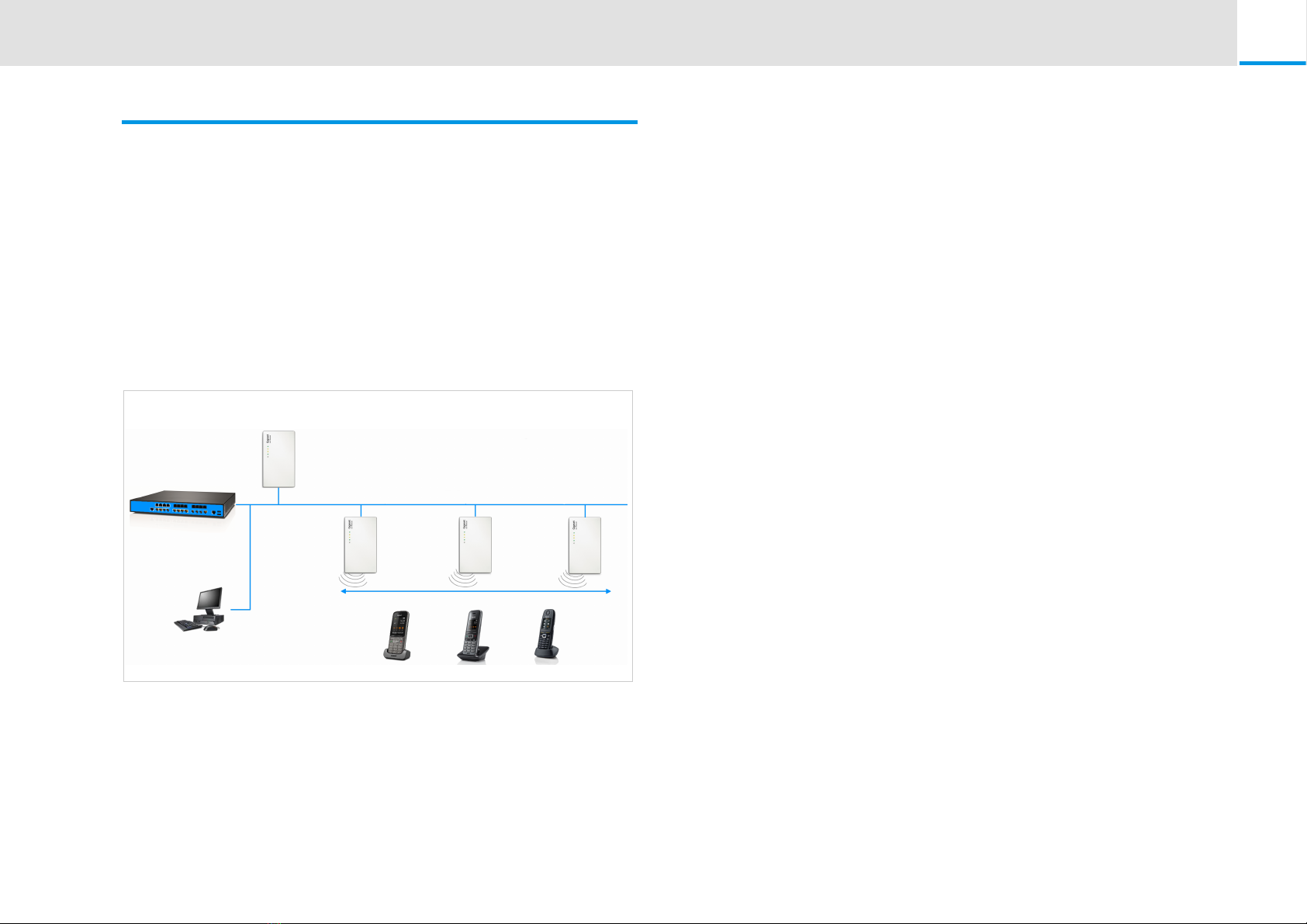
2.1 The SwyxDECT 700 .................................................................................. 4
2.2 Criteria for an optimum DECT wireless network............................... 5
2.2.1 Wireless coverage ............................................................................ 6
2.2.2 Capacity............................................................................................ 6
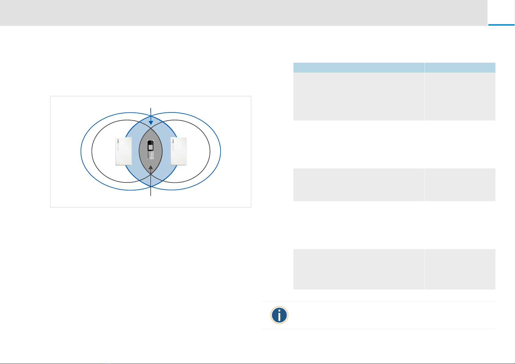
2.2.3 Overlapping and synchronising ...................................................... 7
2.3 How to proceed....................................................................................... 7
Projecting the DECT network.................................................................................... 8
3.1 Determining the requirements for the telephone network............ 8
3.1.1 Subscribers and subscriber behaviour............................................ 8
3.1.2 Environmental conditions................................................................8
3.2 Conditions for the positioning of the base stations ......................... 9
3.2.1 Features of the SwyxDECT 700......................................................... 9
3.2.2 Technical conditions........................................................................ 9
3.2.3 Installation guidelines...................................................................... 9
3.2.4 Synchronisation planning.............................................................. 10
3.2.5 Capacity measurement .................................................................. 11
3.2.6 Material characteristics and interference factors ......................... 13
3.3 Preliminary identification of the positions of the base stations ... 14
3.3.1 Creating a planning drawing ......................................................... 14
3.3.2 Positioning the base stations in the plan ...................................... 14
Taking measurements............................................................................................... 16
4.1 Defining limit values ............................................................................. 17
4.2 Measuring the wireless range of the planned base stations ......... 18
4.2.1 Measurement sequence ................................................................18
4.3 Measuring the cell of a base station................................................... 18
4.4 Measuring the synchronisation overlap of neighbouring
base stations ........................................................................................... 19
4.5 Evaluating measurements .................................................................... 21
Working with the SwyxDECT 700 SPK PRO.......................................................... 22
5.1 Checking the package contents.......................................................... 22
5.2 Further recommended accessories.................................................... 23
5.3 Setting up the measuring base station .............................................. 23
5.3.1 Preparing the base carrier.............................................................. 23
5.3.2 Charging the batteries ................................................................... 24
5.3.3 Alternative power supply............................................................... 24
5.3.4 Mounting the measuring base station on the stand ..................... 25
5.4 Starting up the measuring handset .................................................... 25
5.4.1 Connecting the charging cradle .................................................... 26
5.4.2 Inserting the batteries and closing the battery cover ................... 26
5.4.3 Initial charging and discharging of the batteries .......................... 26
5.4.4 Connecting a headset to the handset............................................ 27
5.5 Operating the measuring handset ..................................................... 27
5.5.1 Display in metering mode.............................................................. 27
5.5.2 Checking the quality of the connection to the measuring
base station..................................................................................... 28
5.5.3 Activating/deactivating the measuring handset ............................ 28
5.5.4 Activating/deactivating speaker mode .......................................... 28
5.5.5 Activating/deactivating metering mode ........................................ 29
5.5.6 Changing the settings for metering mode .................................... 29
DECT installations in special environments........................................................... 31
6.1 DECT networks over several floors .................................................... 31
6.2 Stairwells and lifts.................................................................................. 31
6.3 Several buildings.................................................................................... 31
6.4 Outside area ........................................................................................... 31
6.5 Handover over the whole site............................................................. 32
Help, Enviroment, Care, Accessories...................................................................... 33
7.1 Customer care and help....................................................................... 33
7.2 Environment ........................................................................................... 33
7.2.1 Environmental management system ............................................. 33

2
7.2.2 Disposal.......................................................................................... 33
7.3 Care.......................................................................................................... 33
7.3.1 Contact with liquid ........................................................................ 33
7.4 Authorisation.......................................................................................... 33
7.5 Specifications ......................................................................................... 34
7.5.1 Handset batteries........................................................................... 34
7.5.2 Operating times/charging times for batteries............................... 34
7.6 Accessories ............................................................................................. 34
Glossary ..................................................................................................................... 35
8.1 Bandwidth............................................................................................... 35
8.2 Broadband mode................................................................................... 35
8.3 Cell ........................................................................................................... 35
8.4 Cluster ..................................................................................................... 35
8.5 Codec....................................................................................................... 35
8.6 dBm .......................................................................................................... 36
8.7 DCS .......................................................................................................... 36
8.8 DECT ........................................................................................................ 36
8.9 DECT Manager ....................................................................................... 36
8.10 Erlang ....................................................................................................... 36
8.11 Frame ....................................................................................................... 36
8.12 Frame quality.......................................................................................... 36
8.13 Frequency ............................................................................................... 36
8.14 Handover ................................................................................................ 36
8.15 HD-voice ................................................................................................. 36
8.16 Multi-cell system.................................................................................... 36
8.17 Narrowband mode ................................................................................ 37
8.18 RFP............................................................................................................ 37
8.19 RFPI........................................................................................................... 37
8.20 Roaming .................................................................................................. 37
8.21 RPN........................................................................................................... 37
8.22 RPP............................................................................................................ 37
8.23 RSSI .......................................................................................................... 37
8.24 Slot pair.................................................................................................... 37

Safety precautions 3
1 Safety precautions
Read the safety precautions and the user guide before use.
The device cannot be used in the event of a power failure. In case of a
power failure it is also not possible to make emergency calls.
Do not use the devices in environments with a potential explosion haz-
ard (e.g. paint shops).
The devices are not splashproof. For this reason do not install them in a
damp environment such as bathrooms or shower rooms.
Use only the power adapter indicated on the device.
Use only the cable supplied for LAN connection and connect it to the
intended ports only.
Use only rechargeable batteries that correspond to the specification
(see "Specifications"). Never use a conventional (non-rechargeable)
battery or other battery types as this could result in significant health
risks and personal injury. Rechargeable batteries, which are noticeably
damaged, must be replaced.
If you give your device to a third party, make sure you also give them the
user guide.
Remove faulty devices from use or have them repaired by our Service
team, as these could interfere with other wireless services.
Do not use the device if the display is cracked or broken. Broken glass
or plastic can cause injury to hands and face. Send the device to our
Service department to be repaired.
Using your telephone may affect nearby medical equipment. Be aware
of the technical conditions in your particular environment, e.g. doctor's
surgery. If you use a medical device (e.g. a pacemaker), please contact
the device manufacturer. They will be able to advise you regarding the
susceptibility of the device to external sources of high frequency
energy (for the specifications of the product see Specifications, page 34)

Introduction The SwyxDECT 700 4
2 Introduction
This document explains the preparations necessary to install a multi-cell
DECT network and take measurements for the optimum positioning of
the base stations. It also provides technical and practical background
information.
2.1 The SwyxDECT 700
The SwyxDECT 700 is a DECT multi-cell system for connecting DECT base
stations to a VoIP PABX. It combines the options of IP telephony with the
use of DECT telephones.
The following illustration shows the components of the SwyxDECT 700
and how they are embedded in the IP telephone environment:
SwyxServer DECT
base stations
SwyxDECT
700 Base
DECT Manager
SwyxDECT 700
Manager
LAN
Configuration via
Web interface
Handover & roaming
handsets
SwyxDECT 700 Manager
Central management station for managing the DECT network. One DECT
Manager must be used for each installation.
Manages up to 30 DECT base stations
Manages up to 100 handsets on multi-cell systems
Enables division into subnets (see Cluster, page 35)
Forms the interface to an IP PABX
A Web user interface is available for configuring and administering the
DECT network.
SwyxDECT 700 Base stations
These are the cells of the DECT telephone network.
Each base station can manage up to eight calls simultaneously (see
the see Capacity, page 6)
Handsets
Up to 100 handsets can be connected and up to 30 calls conducted
simultaneously.
Subscribers can accept or initiate calls in all DECT cells with their
handset (see Roaming, page 37), and can also switch between the
DECT cells during a call (see Handover, page 36).
PABX
You can connect your DECT telephone system to a PABX for VoIP, ISDN
or analogue telephony.
Establishes the connection to a public telephone network for ana-
logue, VoIP or ISDN calls.
Enables central management of telephone connections, directories,
network mailboxes, etc.

Introduction Criteria for an optimum DECT wireless network 5
Cluster formation with SwyxDECT 700
You can divide DECT base stations that you have installed at your loca-
tion into several independent groups, i.e., clusters, and manage them
using one SwyxDECT 700 Manager.
The DECT Manager is connected to the base stations and the PABX via
the local network and is therefore not dependent on DECT ranges. This
means that you can install separate DECT islands at your location but
manage them centrally, i.e., they have access to the centrally configured
IP connections, directories, etc.
For further information about the options provided by the SwyxDECT
700, and about installing, configuring and operating the devices men-
tioned, see the relevant user guide.
Swyx offers the SwyxDECT 700 SPK PRO (Site Planning Kit) to help you
with measuring the wireless coverage and quality of your DECT network.
For information on setting up and using the measuring equipment, see
Working with the SwyxDECT 700 SPK PRO, page 22 chapter.
LAN
DECT
Manager
Cluster 1 Cluster 2
2.2 Criteria for an optimum DECT wireless network
A carefully planned DECT wireless network with adequate coverage is
the prerequisite for operating a telephone system that offers good call
quality and sufficient call options for all subscribers in all buildings and
areas belonging to the PABX.
It is difficult to assess the technical wireless conditions of a DECT instal-
lation in advance as they are influenced by many environmental factors.
Therefore, the specific circumstances on-site must be determined by
taking measurements. This produces a reliable statement about the
material required as well as the locations of the wireless units.
Various aspects need to be taken into consideration when planning a
DECT wireless network. The following requirements must be considered
when deciding how many base stations are required and where they
should be placed:
Sufficient DECT wireless coverage of the entire site so that every sub-
scriber can be reached.
Sufficient wireless channels (DECT bandwidth), in particular in "hot-
spots", to avoid capacity bottlenecks.
Sufficient overlap of cells to enable synchronisation of the base sta-
tions and to guarantee freedom of movement for subscribers when
making calls.

Introduction Criteria for an optimum DECT wireless network 6
2.2.1 Wireless coverage
The selection of locations where the base stations are to be installed
should guarantee optimum wireless coverage and enable cost-effective
wiring.
Optimum wireless coverage is achieved if the required reception quality
is delivered at all points of the wireless network. If costs need to be con-
sidered, this should be done with a minimum number of DECT base sta-
tions.
To ensure an interference-free switch of call connections from one cell
to another (handover), there must be an area where good reception is
ensured for both base stations. To achieve this, a minimum quality for
reception must be defined.
2.2.1.1 Signal transmission
The ideal signal transmission of a base
station is shaped like a ring, i.e., so that
the registered handsets can be the
same distance away from the base sta-
tion in all directions without the wire-
less signal being interrupted.
Wireless cell
Base station
Overlap
However, the transmission is influ-
enced by various environmental con-
ditions. For example, obstacles such as
walls or metal doors can impede the
wireless signals or interfere with their
even transmission.
You should investigate the actual con-
ditions that the planned wireless net-
work will be subjected to by
measuring the signal transmission of the measuring base station at
appropriate positions.
2.2.2 Capacity
The capacity of the cells must be large enough to guarantee that the sub-
scribers can be reached in high-density traffic. A cell is at full capacity
when the number of connections required for each base station is larger
than the number of possible connections. A SwyxDECT 700 Base can
manage eight connections simultaneously when operated in narrow-
band mode (see Narrowband mode, page 37). In broadband mode, four
simultaneous connections are possible (see Broadband mode, page 35).
There are two options for increasing the capacity:
Reducing the distance between the base stations.
This means that the cells overlap more,
giving the subscriber access to the base
stations of the neighbouring cells. This
results in a more even wireless quality.
However, this can result in considerable
installation costs for an existing system.
Installing parallel base stations.
The cell size remains generally constant
but the number of possible connections
increases. Installing the base stations
close to one another means that the
additional assembly costs are low, but a
minimum distance must be observed
between the base stations. For further
information please refer to Technical conditions, page 9.).

Introduction How to proceed 7
To keep the costs for the devices and for the installation and mainte-
nance low, as few base stations as possible should be installed.
2.2.3 Overlapping and synchronising
For interference-free cooperation in a multi-cell DECT network, the base
stations must synchronise. In order to synchronise the base stations and
ensure a smooth handover, the cells must overlap.
A sufficient number of large overlapping zones between neighbouring
cells must be ensured. To achieve synchronisation, the reception must
be of sufficient quality to ensure that the base stations can receive one
another securely. For a handover, a handset must have a connection of
sufficient quality to both base stations. You will find information about
possible interferences in section Defining limit values, page 17.
The more densely the base stations are installed, the greater the overlap.
Here, a compromise must be found between keeping the area relatively
open and installing the lowest possible number of base stations.
Handover overlap
Synchronisation overlap
2.3 How to proceed
Use the following guide to quickly locate the most important topics.
Information on ... is located here
Determining the requirements for the tele-
phone network
Determine the requirements for the
telephone network and collect information
about the environmental conditions for the
planned DECT wireless network.
see Determining the
requirements for the
telephone
network, page 8
Creating an installation plan
Create a building plan and enter the planned
DECT base stations in this plan. You should
take account of the general conditions deter-
mined and the technical requirements of
DECT telephony in the process.
see Creating a planning
drawing, page 14
Taking measurements
Use the installation plan to take measure-
ments and adapt the installation plan to your
measurement results.
see Taking
measurements, page 16
Working with the measuring equipment
Have you purchased the SwyxDECT 700 SPK
PRO (Site Planning Kit)? Here you can read
about how to set up the measuring equip-
ment and how to use it to take measure-
ments.
see Working with the
SwyxDECT 700 SPK
PRO, page 22
Special environments
Do you want to set up your DECT network in
a difficult environment?
Helpful information and tips are available
here.
see DECT installations in
special
environments, page 31
If you have any questions about using your measuring devices, please con-
tact our Customer care team (see Customer care and help, page 33).

Projecting the DECT network Determining the requirements for the telephone network 8
3 Projecting the DECT network
There are a number of conditions to be considered when setting up a
DECT network. They affect the subscribers' requirements for the tele-
phone system as well as the technical requirements for the DECT wire-
less network. These conditions must therefore be recorded and
evaluated in a projection phase.
To project your DECT network, proceed as follows:
First determine the requirements for the telephone network and
establish the environmental conditions for the DECT wireless net-
work.
Define how many base stations are required and their probable opti-
mum positioning. Create an installation plan for the base stations.
Take measurements to check whether the positioning of the base
stations at the assumed positions meets the requirements and
whether the reception and sound quality is sufficient everywhere. If
necessary, change the installation plan to optimise the DECT wireless
network.
3.1 Determining the requirements for the
telephone network
Clarify the following questions to determine the requirements for the
telephone network:
3.1.1 Subscribers and subscriber behaviour
How many employees should be able to make calls and how many
subscribers should be able to make calls simultaneously?
How many handsets are required?
How many base stations are required?
Where should telephone calls be possible?
In which buildings (floors, stairwell, basement, underground
garage)?
Outdoors (on footpaths, on the car park)?
For further information please refer to Outside area, page 31.
How are the handsets distributed from a location perspective?
How many calls will be made?
What is the telephony behaviour of the subscribers? How long
is the average call?
Where are the hotspots, i.e., where do a lot of subscribers
gather simultaneously (open-plan office, canteen, cafeteria,
etc.)?
Where are telephone conferences held? How many telephone
conferences are held and how long are these?
3.1.2 Environmental conditions
Where is the site that is to be covered by the DECT wireless network?
Total area of the required wireless coverage
Position and dimensions of the rooms, building plan
Number of floors, basements
What is the basic structure of the building?
What materials and construction types have been used for the
buildings?
What type of windows does the building have (e.g., tinted
glass)?
What construction changes are expected in the near future?
What disruptive influences can be identified?
What are the walls made of (concrete, brick, etc.)?
Where are the lifts, fire doors, etc. located?
What furniture and devices are present or planned?
Are there other wireless sources in the vicinity?
For detailed information on material characteristics and interference fac-
tors, see Material characteristics and interference factors, page 13.
Request a building plan that shows positions and dimensions and that can
be used to document the subsequent installation planning.

Projecting the DECT network Conditions for the positioning of the base stations 9
3.2 Conditions for the positioning of the base
stations
3.2.1 Features of the SwyxDECT 700
A SwyxDECT 700 Manager can manage a maximum of 30 base stations
and 100 handsets.
The DECT network can be divided into clusters; i.e., you can install
several independent DECT islands that are managed centrally by a
DECT Manager.
A SwyxDECT 700 Base base station can establish a maximum of eight
connections simultaneously (four connections in Broadband mode,
see also Broadband mode, page 35).
This must be taken into consideration in the capacity calculations (see
also Capacity measurement, page 11).
3.2.2 Technical conditions
The following values can be used as a guide for the planning. They are
values that are influenced by environmental conditions and that should
therefore be checked via measurements.
The wireless range of a DECT base station for handsets is (guide val-
ues)
Up to 50 m indoors
Up to 300 m outdoors
Ensure adequately sixed overlap zones between neighbouring cells
are taken into consideration. For an interference-free handover, a
spatial overlap of 5 to 10 metres with satisfactory signal strength
should be sufficient, even for fast walking. Neighbouring base sta-
tions must be able to receive one another with sufficient signal
strength to guarantee the synchronisation and handover (see also
Defining limit values, page 17).
Maintain sufficient distance between the base stations as they can
interfere with one another. The minimum distance depends on the
These guide values do not apply to the maximum possible distance
between two base stations. To ensure the handover of a handset from the
cell of one base station to the cell of another, this distance is derived from
the necessary overlap zone.
circumstances. If no obstacles are present, the required distance can
be 5 to 10 metres. If there is an absorbent wall or absorbent furniture
between the base stations, 1 to 2 metres may be sufficient.
You will also find information about possible interferences in section
Material characteristics and interference factors, page 13.
In a horizontal direction, good connections can still be established
behind 2–3 normal brick walls. In a vertical direction and on the
ground floor or in basements, concrete ceilings are difficult to pene-
trate. This means that every floor may have to be supplied separately.
Please note that in empty buildings, adding furniture and equipment
(machines, movable walls, etc.) at a later stage will affect the wireless
quality.
Openings in obstacles improve the technical wireless conditions.
Consider any possible interference factors (see Material characteris-
tics and interference factors, page 13).
3.2.3 Installation guidelines
The following points must be considered when installing DECT base sta-
tions:
For wireless coverage within a building, always install the base sta-
tions on internal walls. For information on installation in an outside
area, see Outside area, page 31.
Depending on the room height, the optimum installation height of a
base station is between 1.8 and 3 m. If you want to install the base sta-
tions at a lower height, interference can occur as a result of furniture
or movable objects. There should be a minimum clearance of 0.5 m
to the ceiling.
We recommend installing all base stations at the same height.
The SwyxDECT 700 Base stations require an Ethernet connection to
the PABX, i.e., it must be possible to connect to the LAN.
The SwyxDECT 700 Base stations are powered by PoE (Power over
Ethernet, IEEE 802.3af). Therefore, you do not normally require a
power connection. However, if you use an Ethernet switch that does
not support PoE, you can use a PoE injector as an alternative. If there
is an option of connecting to the mains power supply in the vicinity
of the base station, you can also use the power adapter to provide a
power supply (to be ordered separately).

Projecting the DECT network Conditions for the positioning of the base stations 10
Do not install the base station in suspended ceilings, cupboards or
other closed furnishings. The wireless coverage can be significantly
reduced, depending on the materials used.
The base station should be installed vertically.
The location and alignment of the base station installed should be
identical to the position deemed optimum during the measurement
stage.
Avoid installation in the direct vicinity of cable channels, metal cup-
boards or other larger metal parts. These can reduce the radiation
and couple into interfering signals. There should be a minimum dis-
tance of 50 cm.
Observe the safety distances and safety regulations. Observe the
regulations specified in rooms where there is a danger of explosions.
3.2.4 Synchronisation planning
Base stations that combine to form a DECT wireless network must syn-
chronise with one another to ensure a smooth transition of the handsets
from cell to cell (handover). No handover is possible between cells that
are not synchronised.
They are synchronised via what is known as an air interface, i.e. via the
DECT wireless network. This means that the signal strength between
neighbouring base stations must be sufficient for synchronisation. The
guide value is a minimum of –70 dBm, but this can also be influenced by
environmental conditions.
For further information please refer to Defining limit values, page 17.
The synchronisation takes place in a master/slave procedure. This means
that one base station (master) defines the synchronisation cycle for one
or more other base stations (slaves). Since it is generally the case that not
all base stations have a good enough connection to all other base sta-
tions in a multi-cell DECT network, it is not possible to have only one
master station and to configure all others as slaves. Instead, you have to
set up a synchronisation hierarchy. You can configure this hierarchy
using the Web user interface of the DECT Manager.
During configuration, assign one level in the synchronisation hierarchy
(sync level) to each base station. Sync level 1 is the highest level; it
Synchronisation always refers to a cluster. You can set up several clusters
that are not synchronised with one another, so there is no possibility of a
handover between clusters.
appears only once in each cluster. A base station always synchronises
itself with a base station that has a better sync level. If it sees several base
stations with a better sync level, it synchronises itself with the base sta-
tion that has the strongest signal. If it does not see any base station with a
higher sync level, it cannot synchronise. A SwyxDECT 700 Base station
shows its synchronisation status with an LED.
For information on synchronising base stations, please refer to the user
guide for the SwyxDECT 700 Base and SwyxDECT 700 Manager.
During the synchronisation planning, make sure that the distance to the-
base station with sync level 1 is as short as possible from all sides, i.e.,
that there are as few levels as possible. It makes sense to select the sta-
tion that is at the centre of your DECT network as the base station with
sync level 1.
Depending on the topology of your DECT network, your synchronisation
hierarchy could look like this, for example.
We recommend giving the base stations a name during planning and enter-
ing the name in the plan. The name should define the unique location in
the building. It is also helpful to document the assignment of the names to
the MAC addresses of the devices.
This makes the configuration of the synchronisation hierarchy in the Web
user interface and the assignment to the installed devices easier later on.
Correct:
Incorrect:
3 2 321
54321

Projecting the DECT network Conditions for the positioning of the base stations 11
3.2.5 Capacity measurement
The capacity of the PABX must be large enough to guarantee that the
subscribers can be reached in high-density traffic. Both the capacity of
the entire PABX and the capacity of the individual cells must be taken
into account.
The capacity of the PABX is determined using the following criteria:
Number of connection channels available
The number of connection channels available defines how many
calls can be conducted simultaneously. Reminder: the number of
possible connections per base station is eight in Narrowband mode
(see Narrowband mode, page 37) and four in Broadband mode (see
Broadband mode, page 35).
Grade of service (GoS)
The grade of service determines the number of connections that may
not be achieved due to the system being at full capacity, i.e., the line
is engaged. A grade of service of 1% means that out of 100 calls, one
cannot be connected for capacity reasons.
The capacity required can be determined using these two factors and the
traffic volume expected.
Please note that the volume of traffic can vary during the course of the
day.
5 4 3
5432
543
13
2
22
2
3
33
33
3
3
4
44
4
44
4
2
1
5432
2
1
1
2
22
2
3
33
3
3.2.5.1 Traffic volume
The traffic volume is expressed in "erlangs (E)". One erlang corresponds
to the continuous full capacity utilisation of one connection channel in a
specific period. Erlangs are usually calculated over an observation period
of one hour. Accordingly, the occupation of a connection channel over
one hour equals one erlang.
For example: if all eight connections of a base station are continuously
occupied, this corresponds to eight E. If a connection is occupied for 20
minutes, this corresponds to 1/3 E.
Examples:
Let us assume that 500 calls lasting 3 minutes each are made within one
hour.
500 x 3 min/60 min = 25 E
Therefore, at least 25 connection channels, i.e., four base stations (in
Narrowband mode), would be necessary for this call volume.
However, this only applies if the grade of service is less than 4%. With a
grade of service of 4%, you need only three base stations, i.e., 24 con-
nection channels. With a grade of service of 4%, it is permissible for 20
calls from 500 not to be established. This means that only 480 connec-
tions have to be achieved. The calculation is as follows:
480 x 3 min/60 min = 24 E
Since the traffic volume is not normally evenly distributed over the site
to be covered, the traffic volume must be calculated for each area
(offices, reception, hotspots, stairwell, etc.) in order to determine the rel-
evant number of base stations that need to be installed.
The capacity must always be adjusted to the highest possible traffic volume
if capacity bottlenecks are to be excluded.

Projecting the DECT network Conditions for the positioning of the base stations 12
The table contains some sample values for the calculation of the traffic
volume depending on the grade of service, call duration and number of
calls per hour.
Using the data you have determined about the telephony behaviour, you
can realistically estimate your requirements.
Alternative calculation for small systems
For smaller systems, an approximate evaluation of the traffic volume can
be sufficient.
Examples:
The traffic volume is evaluated for every area as "low", "medium" or
"high". The evaluation specifies the number of handsets that can con-
duct calls simultaneously as a percentage:
Grade of service Calls at 3 min. per hour
10 50 100 500
0 % 0.5 E 2.5 E 5 E 25 E
2 % 0.49 E 2.45 E 4.9 E 24.5 E
4 % 0.48 E 2.4 E 4.8 Erl 24 E
Grade of service Calls at 15 min. per hour
10 50 100 500
0 % 2.5 E 12.5 E 25 E 125 E
2 % 2.45 E 12.25 E 24.5 E 122.5 E
4 % 2.4 E 12 E 24 E 120 E
Evaluation %Maximum number of handsets that
can be operated from one base station
Low Approx. 10% 80
Medium Approx. 25% 32
3.2.5.2 Hotspots
A hotspot is an area in which more calls than average are conducted
simultaneously, e.g., open-plan offices or other areas where there are a
lot of handsets in a small space.
You can cover such areas with several base stations since the DECT band-
widths in the coverage areas of neighbouring base stations add up. The
DECT standard provides 120 radio channels that can be shared by several
base stations. In practice, however, approximately only one quarter of
these radio channels can be used without special measures, since the
neighbouring channels interfere with one another. This results in a prac-
tical value of a maximum of 30 simultaneous connections. With a maxi-
mum of eight handsets per base station, this means that four SwyxDECT
700 Base base stations would be required.
If we assume that a maximum of 50% of the available handsets are mak-
ing a call simultaneously in a hotspot, 60 handsets can be used with four
base stations.
If interference frequently occurs at a hotspot or more than 30 connec-
tions are required simultaneously, the following measures are possible:
Distribute the base stations that cover the hotspot as widely as possi-
ble at the boundaries of the hotspot so that they are as far away from
each other as possible and mutual interference is minimised.
If this measure is not sufficient, use walls or other suitable means to
diminish the strong signals.
It might also be helpful, if the circumstances at the location allow, to
arrange the base stations in the shape of a ball, i.e., cover the hotspot
through floors and ceilings.
When optimising the coverage of the hotspot areas, make sure that
handsets do not suddenly occupy the call channels of the hotspot base
stations that were previously supplied by other base stations. When
establishing a connection, handsets always occupy channels of the base
station that provides the strongest signal. Therefore, moving the hotspot
base stations may affect other base stations and you may have to relocate
the base stations of the entire network.
High Approx. 50% 16
Evaluation %Maximum number of handsets that
can be operated from one base station

Projecting the DECT network Conditions for the positioning of the base stations 13
3.2.6 Material characteristics and interference factors
There are a number of interference factors that influence the range and
quality of the transmission in particular. The types of interference factors
include:
Interference as a result of obstacles that diminish the signal transmis-
sion, creating radio shadows
Interference through reflection that restricts the call quality (e.g.,
crackling or background noise)
Interference through other radio signals that can lead to errors in
transmission
3.2.6.1 Interference through obstacles
Possible obstacles are:
Building constructions and installations such as reinforced concrete
ceilings and walls, stairwells, long corridors with fire doors, uptakes
and cable channels.
Metal-clad rooms and objects such as cold stores, computer rooms,
metallised glass areas (reflections), firewalls, tank systems, refrigera-
tors, electrical boilers etc.
Movable metal objects such as lifts, cranes, carts, escalators, shutters
Room furnishings such as metal shelves, filing cabinets
Electronic devices.
It is often difficult to locate the exact source of the interference; particu-
larly if the reception power of the local DECT signals fluctuates strongly
within a few centimetres. In these cases, the interference can be reduced
or corrected by small changes to the position.
Wireless coverage in lifts is normally poor or not available at all (see also
Stairwells and lifts, page 31).
3.2.6.2 Loss of range through building materials in comparison to a free
wireless field:
3.2.6.3 Interference from other cells and networks
DECT is very robust against interference from other wireless networks.
For example, co-existence with WLAN is not a problem. Most other asyn-
chronous DECT single base stations do not present a problem either.
Problems may occur in special cases, such as an environment where
there is a very high level of DECT usage. This applies when there are co-
existing asynchronous DECT base stations but, even more so, when base
stations have been installed too close together to cover a hotspot, for
example.
Despite sufficient signal strength, the following interference can occur:
Unexpected termination of the connection
Loss of synchronisation of handsets
Poor voice quality
Glass, wood, untreated Approx. 10%
Wood, treated Approx. 25%
Plasterboard Approx. 27 – 41%
Brick wall, 10 to 12 cm Approx. 44%
Brick wall, 24 cm Approx. 60%
Aerated concrete wall Approx. 78%
Wired glass wall Approx. 84%
Reinforced concrete ceiling Approx. 75 – 87%
Metal-coated glass Approx. 100%
When interference occurs because base stations are installed too closely
together, try to resolve the problem with the measures described in the
Hotspots section (increase the distances, use obstacles to absorb the inter-
ference, see also Hotspots, page 12).

Projecting the DECT network Preliminary identification of the positions of the base stations 14
Summary
Wireless traffic interference can have many causes that cannot all be
determined in advance, that increase or decrease due to mutual influ-
ences and that can change during operation.
Therefore, the actual influence of interference factors on reception and
voice quality can only be determined by taking measurements. However,
the measurements also only provide an image of the wireless network at
the time of measurement. We therefore recommend that when you plan
the DECT network areas where interference can be expected, you err on
the side of caution when you interpret the limit values.
3.3 Preliminary identification of the positions of
the base stations
Now plan the positions of the base stations. Take the following into con-
sideration:
The information you have collected regarding the requirements for
the telephone network
Your synchronisation planning
The technical conditions for the wireless DECT.
First create a plan in which you then enter the locations of the base sta-
tions. You can use existing building and supply plans, if applicable. For
very large buildings, you may be able to work with partial floor plans and
then merge the results of the measurements into the evaluation.
3.3.1 Creating a planning drawing
Create a planning drawing from the information you have collected in
the preliminary examination of the location. Enter building dimensions,
hotspot areas and any sources of interference already identified.
Example:
If you have found other DECT sources, check whether you can switch
them off, relocate them or integrate them in your DECT network.
The numbers in the rooms reflect the required number of DECT tele-
phones.
Areas with high-density traffic are marked as hotspots (HS).
The walls marked in bold are assumed to have a high absorption
effect, or reflections can be expected.
The dotted lines on the two outer walls indicate tinted windows
(coated with metal film).
The stairwell should be covered by DECT wireless transmission.
There is a lift here.
3.3.2 Positioning the base stations in the plan
Now enter the base stations.
30 m
50 m
HS
HS
WC/
store
Stairs
Computers

Projecting the DECT network Preliminary identification of the positions of the base stations 15
The example shows five base stations.
One base station is used to show how, by drawing in transmission
directions for the wireless signal, you can estimate how many base
stations can see each other and which building areas the wireless sig-
nal could reach.
For the hotspot in the room at the top left, two additional base sta-
tions have been planned in parallel.
If full wireless coverage is required for the stairwell, measurements
must be performed to check whether a further base station has to be
located here.
You must also check whether the base stations planned are sufficient
for the second hotspot.
You then check these initial assumptions later using the measurements,
see chapter 4, Taking measurements, page 16.
WC/
store
Computer
Stairs
HS
HS

Taking measurements 16
4 Taking measurements
You have:
Determined the requirements for the telephone network, see Deter-
mining the requirements for the telephone network, page 8,
Planned the number of base stations and their positions, see Prelimi-
nary identification of the positions of the base stations, page 14,
Set up and operated the measurement equipment.
If you are using the SwyxDECT 700 SPK PRO (Site Planning Kit), you
can find information about setting it up on Working with the Swyx-
DECT 700 SPK PRO, page 22.
You can now start the measurements for your planned DECT network.
The aim of the measurements is to determine the following:
Is sufficient wireless coverage and a good voice quality guaranteed
everywhere in the desired area?
Is synchronisation of the bases stations ensured in their planned
positions?
Is a handover between the base stations possible where it is
required?
The requirements from these three aspects must be taken into account
in the measurements. For information on this, please also refer to sec-
tion Conditions for the positioning of the base stations, page 9.
Notes for taking the measurements
Take two different measurements:
Measure the connection quality in the wireless coverage area
for the planned base stations.
Measure the signal strength between the base stations (syn-
chronisation measurement).
To measure the connection quality, establish a telephone connec-
tion. It is helpful if the measurements are performed by two people,
since they can check the voice quality and interference on both
measuring handsets directly in a call. If only one person performs the
measurements, the connection quality can be checked using the test
tone of the base station )see Switching on the continuous test tone for
the base station, page 28).
You can also test the connection quality by holding the handset to
your ear as you measure, in the same way as you would in a real
telephony situation. Turn around as you do so. Note how the acous-
tics quality of the test tone changes. If interference occurs at the limit
of the range (e.g., crackling), power at the measuring site is critical.
Your head can impair reception. For this reason, the test against your
ear is an additional check for verifying the reception quality in limit
areas.
Use the measuring handset in idle status to measure the signal
strength between the base stations, as it is the measured signal
strength and not the voice quality that is relevant in this situation.
Using the stand, position the measuring base station as precisely as
possible in relation to the intended position for the base station.
To measure the signal strength between base stations, position the
measuring handset in the exact planned position of the base station.
For example, if you want to position the base stations at a height of 3
m, make sure the measuring handset is at this height.
Move metal objects as far away as possible from the measuring base
station as they can influence the measurement.
Document the progress of the measurement by entering it in the lay-
out plan (horizontally and, where applicable, vertically) and in a
measurement log.
In order to be able to recognise subsequent changes, it is helpful to
document the planned assembly positions of the individual meas-
urement series and their environment with photographs.
If the PABX is to be used for several floors or very high rooms (e.g.,
with a gallery), you must also measure the vertical range and enter it
in a plan of the building.
For further information please refer to DECT installations in special
environments, page 31.
Fluctuations in the measurement result
When you are performing the measurements, the signal strength dis-
played on the handset can fluctuate strongly, particularly if you are mov-
ing around with the handset. The base stations have two aerials, so the
handset displays the values for the aerial for which it receives the best
signal. Since the measuring handset takes measurements at defined time
intervals (2.5 seconds as standard), the values can change quickly.
For example, if you block the signal for the aerial that is in a better posi-
tion for the handset with part of your body, the handset receives the sig-
nal from the weaker aerial. Turning your body slightly can significantly
alter the measurement value, since the handset is suddenly able to

Taking measurements Defining limit values 17
receive the signal from the "better" aerial. By moving around, you deter-
mine an average value that you can use as the measurement value.
If the fluctuations are strong, it makes sense to perform the measure-
ment while a connection is established as you then have an additional
check based on the voice quality.
When the PABX is being operated in real-life situations, these fluctua-
tions are barely noticeable as the base stations automatically establish
the connection with the best positioned aerial.
4.1 Defining limit values
During the measurement process, the measuring handsets receive wire-
less signals from the measuring base station and display various charac-
teristics for the reception quality. The following are relevant for the
reception quality:
Reception power
Connection quality
The values specified below are guidelines for determining limit values
for operating the DECT telephone system under optimum conditions.
Since the DECT network can be restricted by many factors that can also
occur temporarily, we do not recommend positioning the base stations
at the limit values. Instead, you should include a buffer according to the
requirements for grade of service and voice quality. It may be acceptable
for example, that voice quality is restricted at times in the basement, and
that calls cannot always be made there. In contrast, restrictions are unac-
ceptable for meeting rooms where telephone conferences are held.
Reception power
The reception field strength is measured to assess the quality of trans-
mission. The reception power (proportional to the field strength) is dis-
played on the measuring handset in dBm (see dBm, page 36). A very good
reception power is approximately –50 dBm. Systems that are measured at
up to –60 dBm generally offer a good quality. For measurements up to –
70 dBm, the measurement must be checked and evaluated with an audio
connection to ensure sufficient quality. A handover is no longer possible
in this area.
Different limit values can be used for the measurement, based on the
quality or use of specific areas (e.g., office, corridor, basement). Different
quality requirements can also be defined at the various base stations
within a partial system.
Typical limit values for normal, low-interference environments are:
Limit value for secured voice quality: –65 dBm
This is the value at which a handset must receive the signal of a base
station for a subscriber to be able to benefit from good quality
telephony. For an interference-free handover, the handset must
receive both base stations at this level of quality.
Limit value for synchronisation: –70 dBm
This is the value at which a base station must receive the signal of
another base station to be able to synchronise.
The following table gives an initial guideline for the quality of the wire-
less connection.
Connection quality
In principle, the measurement of the field strength should always be
supplemented by a check of the connection quality. Interference, e.g.,
through reflection or external systems that influence the voice quality,
can also occur with good reception power.
Therefore, in addition to the reception power, the frame qualityis also
displayed on the measuring handset (see Frame quality, page 36). This
indicates the percentage rate of the packages received without errors in
a measurement interval. The optimum value is 100%.
Reception power Evaluation of the quality
–50 dBm Very good
–60 dBm Good
–65 dBm Satisfactory
–70 dBm Adequate
–73 dBm Weak, not suitable
–76 dBm Poor, not suitable
Reception power Frame quality Evaluation of the quality
–60 dBm 100 % Good
–60 dBm 99 % Satisfactory
–60 dBm 98 % Adequate

Taking measurements Measuring the wireless range of the planned base stations 18
4.2 Measuring the wireless range of the planned
base stations
Take two different measurements.
1. Measure the connection quality between the measuring handset
and measuring base station in their wireless cells to ensure that
sufficient voice quality is guaranteed at every position in the
required coverage area. Taking the same measurement for the
neighbouring station produces the overlap zone required for a
handover.
2. Measure the strength of the signal from the measuring base station
that you receive at the planned position of the neighbouring base
station to ensure sufficient synchronisation overlap.
4.2.1 Measurement sequence
The sequence in which you measure the wireless range of the planned
base stations depends on the size of your DECT network and your
assumptions with regard to the existing "problem areas". As a rule of
thumb, first measure the base stations whose positions have the least
leeway.
Take the following aspects into consideration:
Assumed problem areas
For base stations that are to cover specific problem areas, e.g., a stair-
well or entrance area, there are often few alternative positioning
options. In this case, measure these base stations first because the
positioning of all other base stations depends on these initial posi-
tions.
For large installations
The more base stations you use, the higher the requirements of the
synchronisation hierarchy (see Synchronisation planning, page 10). In
this case, we recommend starting with the base station for which a
subsequent change would mean the greatest effort. This is usually
–60 dBm 97 % Weak, not suitable
–60 dBm 96 % Poor, not suitable
Reception power Frame quality Evaluation of the quality the base station with sync level 1. Start here and move outwards from
sync level to sync level.
For small installations
Here it makes sense to start with the base station where the highest
call traffic is to be expected, e.g., base stations in hotspots or other
high-traffic areas. Once the coverage of these areas is ensured by
measurement, check the positioning of the other base stations.
4.3 Measuring the cell of a base station
1. Temporarily secure the measuring base station in the position in
which the base station is to be installed.
2. Establish a telephone connection between the two measuring
handsets or activate the continuous test tone of the measuring base
station (see Switching on the continuous test tone for the base
station, page 28).
3. Move away from the base station with the handset, observing the
display and the signal in the earpiece, until the limit value of –65
dBm is displayed or a wireless transmission boundary is reached
(e.g., lift, exterior wall). Transfer this point to your plan and enter the
value in the measurement log.
4. Use this method to determine the border line around the base
station. The theoretical ideal case of a ring-shaped transmission is
considerably altered in reality by walls (depending on the
construction material) and metal furnishings.
5. Check the voice quality in the limit areas using the connection to
the second measuring handset or the measuring tone of the base
station.
6. Enter deviations in the reception signal measurement of the voice
quality in the layout plan or the measurement log.
Table of contents
Other Swyx Telephone manuals

Swyx
Swyx SwyxPhone D750 User manual

Swyx
Swyx SwyxPhone L66 User manual

Swyx
Swyx SwyxPhone D863 User manual

Swyx
Swyx SwyxPhone D565 User manual

Swyx
Swyx SwyxPhone L615 User manual

Swyx
Swyx SwyxPhone D765 User manual

Swyx
Swyx SwyxPhone S315 User manual

Swyx
Swyx SwyxPhone D210 User manual

Swyx
Swyx SwyxPhone D843 User manual

Swyx
Swyx SwyxPhone L400 Operator's manual