Sybility L-PHONE II Training manual

Important!
Please read carefully before use.
Keep for later reference.
Commissioning instructions
Ergonomic-telephones
L-PHONE II
L-PHONE II-f

Copyright
All rights to this documentation are reserved, in particular but not limited to
the rights of copying, distribution and translation.
No portion of this documentation may be reproduced, edited, copied or
distributed in any form without prior written authorization from Sybility
GmbH.

1
Content
1 Guide to this manual.................................................................... 2
1.1 Parts of the documentation ............................................................ 2
1.2 Signal words and symbols.............................................................. 3
2 Safety information........................................................................ 4
3 Initial operation............................................................................. 7
3.1 Safety information .......................................................................... 7
3.2 Scope of supply.............................................................................. 7
3.3 Check the phone referring transportation damage......................... 8
3.4 Connecting the telephone .............................................................. 8
3.5 Insert name plates.........................................................................11
3.6 Put on the dial pad cover.............................................................. 12
3.7 Wall mounting............................................................................... 13
3.8 Prepare the radio pendant TRX (only “L-Phone II-f” version)....... 15
4 Take the phone out of operation............................................... 18
4.1 Turno/Disconnectthephone ..................................................... 18
4.1.1 Turnthephoneo ...................................................................... 18
4.1.2 Disconnectthephone................................................................. 18
4.2 Disposal........................................................................................ 18
5 Technical data............................................................................. 19
5.1 Technical data of the telephone ................................................... 19
5.2 Technical data of the radio pendant TRX ..................................... 20
6 Index ............................................................................................ 21

2
Guide to this manual
1 Guide to this manual
1.1 Parts of the documentation
The manual is a part of the product. Keep it for the period of product life. If
you pass over the product to others, please hand over the manual too.
Instructions on commissioning
The manual is intended for the installer of the phone. It describes how the
phone is properly installed and connected.
Programming instructions
The manual is intended for the installer of the phone. It describes how the
functions with PIN authorization are set.
User manual
In this manual, the user of the phone learns, how to use the phone and
how to program functions without PIN authorization.

3
Guide to this manual
1.2 Signal words and symbols
Signal words and symbols in this guide refer you to warning advice, infor-
mation and instructions.
Signal word/
symbol
Explanation
DANGER
Warning advice.
Directandimmediatedanger.Failuretocomply
will result in death or serious injury.
WARNING
Warning advice.
Possiblydangeroussituation.Failuretocomply
could result in death or serious injury.
CAUTION
Warning advice.
Possiblydangeroussituation.Failuretocomply
could result in slight or minor injury or damage to
equipment.
Helpful information.

Safety information
4
2 Safety information
Intended use
The phone is suitable for connection to the public telephone network and
for connection to analog ports of telephone systems.
Attheportthephone„L-PhoneII/L-PhoneII-f“isconnected,noother
phone can be operated (e.g. via simple parallel connection).
Shock hazard
DANGER
Never try to unscrew the screws and open the device.
You could get in contact with current-carrying parts.
Never touch the connector contacts with pointed or
metallic objects.
Donotmaketelephonecallsduringathunderstorm.
There is risk of electric shock when a lightning strike into
the net.
If the phone housing or connecting cables are damaged,
unplug the connecting cable from the telephone network
and, if connected, the power supply unit from the mains.
Installation location
The telephone socket and the mains outlet should be located nearby the
installation location.
CAUTION
The telephone was produced for standard use conditions.
Please do not install the device
close to heat sources (air-conditioning, heater, exposure
to direct sunlight),
in humid rooms (no exposure to splashing water or che-
micals),
nearbydevicesemittingstrongmagneticelds(electrical
appliances,uorescenttubes,computers,TVsets),
in dusty rooms,
in rooms where the device is exposed to vibrations or
extreme variations in temperature.

Safety information
5
The phone do not be exposed to ambient temperature
below 0°C or greater than 40°C.
If you do not observe this, the device may be damaged.
Some furniture lacquers or furniture cleaning products may
attack the rubber at the feet of the telephone and thus
cause patches. In such cases, please use a nonslip pad
under the device.
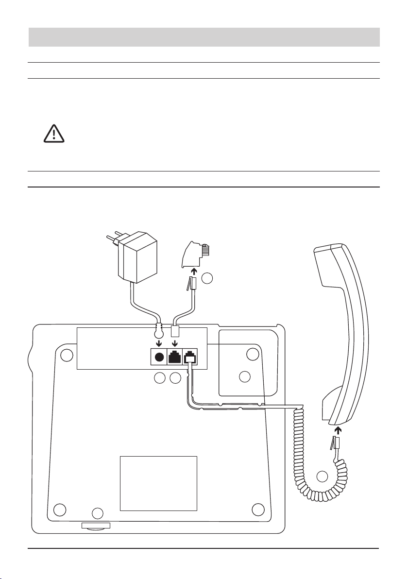
Installing the telephone
DANGER
If the telephone and the connecting cables are damaged,
it is not allowed to connect the phone to the telephone
socket and the mains outlet. Electric shock may result.
CAUTION
Only use original components from the scope of supply.
Only plug the connecting cables into the designated
receptacles. If you do not observe this, the device may
be damaged.
The connected power supply unit must be freely access-
ible, so that in a hazardous situation (defect on the
phone or on the power supply unit) it can be separated
directly from the mains.
Operating the phone
CAUTION
Never carry the telephone at the handset or the connec-
tion cables. The plugs and sockets could be damaged.
No liquid may get into the device, because this can da-
mage the device.
Alerting/emergency call
DANGER
In rare cases, the function of sending out an emergency
call to the call system or to a freely programmable
destination cannot be guaranteed. This might be the case
if e. g. the telephone network fails. If the device is used
for people who are in a critical or life-threatening health
condition, you should not refrain from additional safety
means.

Safety information
6
Duringoperation,thephonemustbeconnectedtothe
telephone network and the power grid. The battery pack
must be inserted so that enough power is available du-
ring a power failure.
In the battery icon appears in the display, the battery
pack has to be replaced.
Emergency radio pendant
Variant„L-PhoneII-f“only.
Useonlyapprovedpendants/transmitters.
The pendant is protected against water jets. A longer
immersion in water can damage the transmitter.
Interferences may occur if electrical appliances such as
vacuumcleanersetc.withinsucientordefectiveradio
interference suppression are operated nearby.
CAUTION
If the radio pendant is worn around the neck by means of
the cord, please consider the following:
The wireless pendant should only be worn in front of the
upper part of the body and above the clothing. It then can
easily be accessed at any time.
The cord has been developed and designed to break
when exposed to extra ordinary high mechanical load.
Despiteofthis,ariskofinjurycannotbecompletelyex-
cluded. It is recommended to wear the wireless pendant
around the wrist when helping laid up persons.
Onlyuseanoriginalcordtoreplaceafaultyone.Donot
try to repair the cord on your own (e. g. by making a
knot).
Wireless pendant and cord should be kept out of reach of
small children.

7
Initial operation
3 Initial operation
3.1 Safety information
In chapter 2 „Safety information“ the intended use of the phone is de-
scribed.Youwillalsondtheconditionsofasuitablelocationandother
requirements for commissioning.
Read the safety information before operating the phone!
3.2 Scope of supply
The content of the package is:
• 1 telephone and handset
• 1 telephone connecting cable and TAE-adapter
• 1 curled cable (handset cable)
• 1 dial pad cover
• 1 battery pack
• 1 power supply unit
• 1 user manual
• 1 commissioning instructions
• 1 programming instructions
• Name plate and plastic cover for the speed dialling keys. Plate and a
plasticcoverfor“police/reservicenumbers”.
In addition, in the variant „L-Phone II-f“:
•1radioreceiver,integratedinthephone
•1radiopendantTRXincludedcord.
Plug for the telephone connection
The telephone line cord included connecting plug may be
country-specicdierent.Thefollowingdescriptionrefersto
the German TAE plug. In the special variants no TAE adap-
ter is attached.

8
Initial operation
3.3 Check the phone referring transportation damage
Check the phone referring transportation damage before connecting it.
WARNING
If the phone housing or connecting cables are damaged,
it is not allowed to connect the phone to the telephone
network. It may cause electric shock.
3.4 Connecting the telephone
Read the safety information in chapter 2 before connecting the phone!
ConnectthephoneasshowninFig.1.
Fig.1
1
2
3
4
5
6

9
Initial operation
1Insert/exchange the battery pack
The battery pack is used for power failure protection.
The battery pack may be used and replaced only by autho-
rized technicians.
WARNING
Forsafetyreasons,thebatterypackshouldbereplaced
every 3 years. Battery packs are available as accessories.
Insert only original battery packs. Other battery packs may
explode during operation and damage the phone.
Forsafetyreasons,disconnectthetelephonefromthetele-
phone network and the power supply system before insert-
ing/exchangingthebatterypack.Electric shock may result.
Insert/exchange the battery pack
• Unscrew the screw above the rubber foot.
• Remove the cover of the battery compartment
• Plug the connector of the battery pack into the socket in the housing.
Insert the battery pack into the compartment
• Close the battery compartment cover and make sure that the cover is
locked again. Screw on and tighten the screw.
Remove the battery pack
WARNING
When pulling out the connecting cable of the battery there
isariskoftearingothecable.Thiscancausethebattery
to explode and a short circuit.
• Lift the connector with a suitable tool, for example, tweezers, carefully
outofthesocket.Donotpullontheconnectioncables.
• Disposeoftheoldbatterypackproperly(donotthrowinthehousehold
waste).
2Connect handset
Plug the curled handset cable plug at the longer uncurled end into the
jack on the bottom of the device. Plug the other plug into the handset jack.
Insert the handset cord into the cable channel. Instead of the handset,

10
Initial operation
you can also connect a headset. In this case the telephone must be set to
„headset mode“.
3Prepare the telephone connection cable
Plugthecountry-specicadapteronthewesternplugofthecable(ifnot
already connected).
4Connect the telephone connecting cable
CAUTION
Only use the telephone connecting cable from the scope of
supply.Othercablesmayhaveadierentpinassignment
with the result that the phone does not work.
Insert the small plug into the socket of the phone, the larger into the tel-
ephone socket.
5Connect the power supply unit
CAUTION
Use only the power supply unit from the scope of supply. It
must be freely accessible, so that in a hazardous situation
(defect on the phone or on the power supply unit) it can be
separated directly from the mains.
Insert the small round plug into the socket of the phone, the larger into a
230Vsocket.
6SD card slot
The compartment can be opened by the installer of the phone, if a soft-
wareupdateoracongurationshouldbecarriedoutfromortoacard.
The recording of a personal emergency announcement must also carried
outviatheSDcard.
UsestandardSDcardswithacapacityofmax.2GB(FAT16format).
CardswithhigherstoragecapacitymustbeformattedinFAT16.Remove
the write protection.

11
Initial operation
78 9
0 #
Fig.2
• Graspwiththeforengerinthehollowleftofthemicrophoneandpullo
the cap.
• PushtheSDcardintotheslotuntilitlocks.Viaaslighttouchpressure
the card snaps out for taking out.
3.5 Insert name plates
Name plate for speed dialling keys
• Write down the speed dialling addresses
Monika
Lothar
Horst
Franz
Martin
Erna
Max
and lay the name plate into the slot.
• Slide the plastic cover into the upper gab
(seegureontheright),curveitandpush
the other end of the cover into the other gap.
Fig.3
• Exchange name plate: Use the wire of a paper clip or another suitable
tool to reach into the lower plastic cover’s gap. Pull the plastic cover
in an upward direction and remove it.
Pre-printed inlay plate and plastic cover for “police/re brigade”
• Writethepolicecallnumberandtherebrigadenumberonthepre-
printed inlay plate. Insert the plate in the recess on the left side of the
housing. Replace the plastic cover.
• Exchange inlay plate: Take the plastic cover at the top left side (handset
rest) and pull it in an upward direction. The cover comes out of the hol-
der.

12
Initial operation
3.6 Put on the dial pad cover
The dial pad cover serves as an aid for dialling. You can install and re-
move the cover as desired. The dial pad cover is comprised in the scope
of supply.
Caps
123
Fig.4 Fig.5
Useyourngersorasuitabletooltoremovethecaps(seeg.4).The
caps might be reused later so keep them in a safe place.
Place the dial pad cover
• Placethedialpadcover(seeg.5)onthehousing.
• Press the two plastic hooks of the dial pad cover into the corresponding
housing slots and tighten the cover. .
• Use two hands to push the dial pad cover towards the lower side of the
housing until the two lower hooks snap into place.
Remove the dial pad cover
• Turnthephonearoundandslidethebladeofaatscrewdrivercarefully
between housing and pad cover. Press the cover carefully away from
the housing, so that the hooks can disengage from the housing. Remo-
ve the cover.
• Replace the plastic caps afterwards.

13
Initial operation
3.7 Wall mounting
The telephone can be wall-mounted using a metal holder. This holder is
available optionally.
Prerequisites for wall-mounting:
You have connected the handset, inserted the battery pack and the plates
andifdesired,thedialpadcoverisxed.
Adjust handset rest for wall-mounting telephone operation
• Pressthedetentwiththengernailinthedirectionofthearrowas
showning.6.
• Take the detent out of the recess, turn
it round (180 degrees) and replace it
afterwards. The upper part of the
detent is now in a better position for
wall-mounting telephones as it can
hold the handset.
Fig.6
Fix metal holder for wall mounting
Fig. 7

14
Initial operation
• Positionthemetalholderonthewall(youmaypossiblyplacetheround
opening of the holder on a concealed telephone wall socket directly).
• Markthepositionoftherequireddrillholesonthewall.
DANGER
Makesurethatnocablesareinthedrillingarea.
• Drilltheholesandscrewthemetalhousingonhorizontally.Compensate
possible strain within the metal housing.
Preparing the connecting cables
Initial state: Telephone connecting cable and power supply unit are not
plugged.
• Lead the power supply unit connecting cable through the rectangular
opening of the metal holder (from the bottom towards the top).
• Connectthepowersupplyunittothephone(seeFig.1).
• If the telephone wall socket is positioned below the holder: Lead the
telephone connecting cable through the rectangular opening of the
metal holder (from the bottom towards the top).
• ConnectthephonetotheC/Oline(seeFig.1).
• If you could place the round metal holder opening on a concealed tele-
phone wall socket directly, the telephone connecting cable can be kept
in the hollow space of the metal holder. The telephone plug is to be
plugged in the telephone socket.
How to hook the telephone
• Remove all 4 rubber feet.
• Grasp the phone with both hands and hang the lower rubber feet ope-
nings into the two lower hooks of the metal holder.
• Press the phone with both hands up until the two upper hooks engage
in the rubber feet openings.
How to unhook the telephone
Take out the above procedure - in reverse.

15
Initial operation
Connect the telephone
Connect the phone with the telephone network and the mains.
3.8 Prepare the radio pendant TRX (only “L-Phone II-f” version)
ATTENTION Read the safety information in chapter 2 on the pages 5 - 7.
CAUTION
Only use original radio pendants TRX!
The radio pendant is delivered with a cord. The cord can be worn around
theneck.Alternativelyweoerablackelasticstrapasanaccessory.
Attaching the strap
There are two long loops at the back of the pendant where you can draw
through the strap. Straps are available as accessories.
Fig.8Backofthependantwithoutstrapontheleftandwithstraponthe
right
Changing the cord
Unscrew the pendant and remove the cord. Insert the new cord and screw
the shells of the pendant tight. Be aware that the sealing lip of the lower
shell is properly seated in the recess of the upper shell before screwing
the pendant tight.

16
Initial operation
Take out the old
cord and insert the
new cord.
Fig.9Pendantwithcord,Fig.10Lowershell
Changing the battery
Youneedacoincelllithium3VCR2032.
Unscrew the pendant. With a suitable tool press out the coin cell in direc-
tionofthearrow(seeg.11).Insertthenewcoincellagainstthearrow
direction. The side of the coin cell with the smaller diameter faces down-
wards. Be aware that the sealing lip of the lower shell is properly seated in
the recess of the upper shell before screwing the pendant tight.
Fig.11Batteryinthelowershell
ATTENTION Programming the pendant
Programm the radio pendant only after having connected
the telephone to the power supply system! If the radio
pendant is programmed, the radio receiver inside of the
telephone discharges the battery pack very quickly, if the
telephone is not connected to the power supply.
Battery life
The lifespan of the pendant’s battery in normal use (func-
tional test once a week, emergency call only in an emer-
gency) is up to 10 years.

17
Initial operation
Protection class
The pendant is dust-tight and protected against water jets
according to protection class IP 65.
Radio coverage
Up to 30 m in buildings (depending of the building struc-
ture), up to 250 m outdoors
LED
The2-colorLEDofthependantlightsupafterpressingthe
buttonshortlyred(conrmationoftheactivation)andthen
green (acknowledgment of receipt by the radio receiver).

18
Take the phone out of operation
4 Take the phone out of operation
4.1 Turn o/Disconnect the phone
4.1.1 Turn the phone o
Anunusedtelephonecanturnedoforatimeofmax.3days.Inthisstate,
the phone needs very little power from the battery pack.
Open Menu > press toselect„MenureleasePIN“
> Ok.
Enter 4-digit PIN > Ok.
Press to select „Service“ > Ok.
Press toselect„Deviceo“>Ok.
Forturningthephoneonconnectittothemains.Theunitisnowreadyfor
use again.
4.1.2 Disconnect the phone
Disconnectthephonefromthetelephonenetworkand,ifconnected,even
from the mains. The battery pack should be removed only by an author-
ized electrician.
4.2 Disposal
Packaging:Disposeofcardandcardboardboxesintheusedpapercon-
tainer and throw plastic parts into a recycling container.
Device disposal: Used electrical devices should not be disposed of in
thehouseholdwaste.Disposeofthedeviceatyourlocalcollectionpoints
(scrap or recycling yards). Please contact your local authority for informa-
tion on disposal sites.
(Rechargeable) batteries: (Rechargeable) batteries may
not be disposed of in the household waste. As a consumer,
you have a legal obligation to return (rechargeable) batteries.
Please contact your local authorities, or the specialist retailer
from where you purchased the device, for information on
disposal sites.
Other manuals for L-PHONE II
1
This manual suits for next models
1
Table of contents
Other Sybility Telephone manuals