INTRODUCTION
First and foremost we would like to thank you for purchasing this product.
Our commitment to satisfying our customers can be seen from our ISO-9001 certification and from the manufacturing of
products like this one.
Its advanced technology and exacting quality control will ensure that customers and users enjoy the many features this
system offers. To obtain the maximum benefit from these features and a properly wired installation, we kindly
recommend that you spend a few minutes of your time reading this manual.
INDEX
2
SAFETY PRECAUTIONS
- Install or modify the equipment without the power connected.
- The installation and handling of these equipments must be performed by authorised personnel.
- entire installation must be at leastThe away from any other40cm installation.
.
- Do not overtighten the screws on the terminal block.
- and place without risk of drop or water projectionsInstall the telephone in a dry protected .
-Avoid to place it near to heating sources, in dusty locations or smoky enviroments.
- Before connect the system , panel, power supply and telephonesing to the mains check the connections between door .
- Do a enclosed informationlways follow the .
Introduc ....................................................................................................................................................................2tion
Index.............................................................................................................................................................................. 2.
Safety precautions........................... ................................................................................................................. 2............. .
Characteristics............................................................................................................................................................... 2
System operation........................................................................................................................................................... 3
Monitor description..................................................................................................................... ......................................
.......................................................................................................................................................... ........3Description .
..................................................................................................................................................3Function push buttons
........................................................................................................................................ ........3Connection terminals ...
.............................................................................................................................. .....3Call volume control ....................
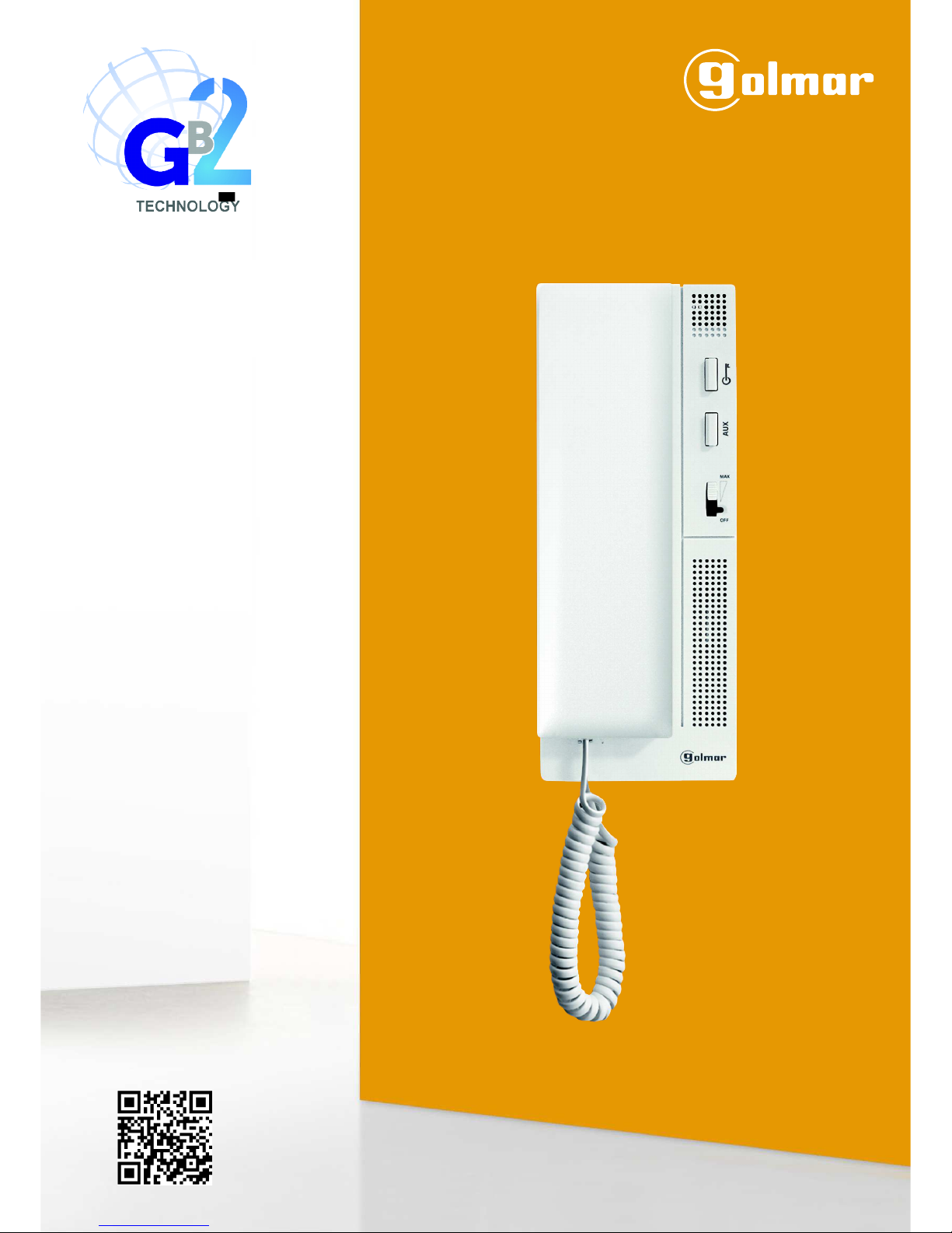
............................................................................................................................. ....4Configuration dip switch ..............
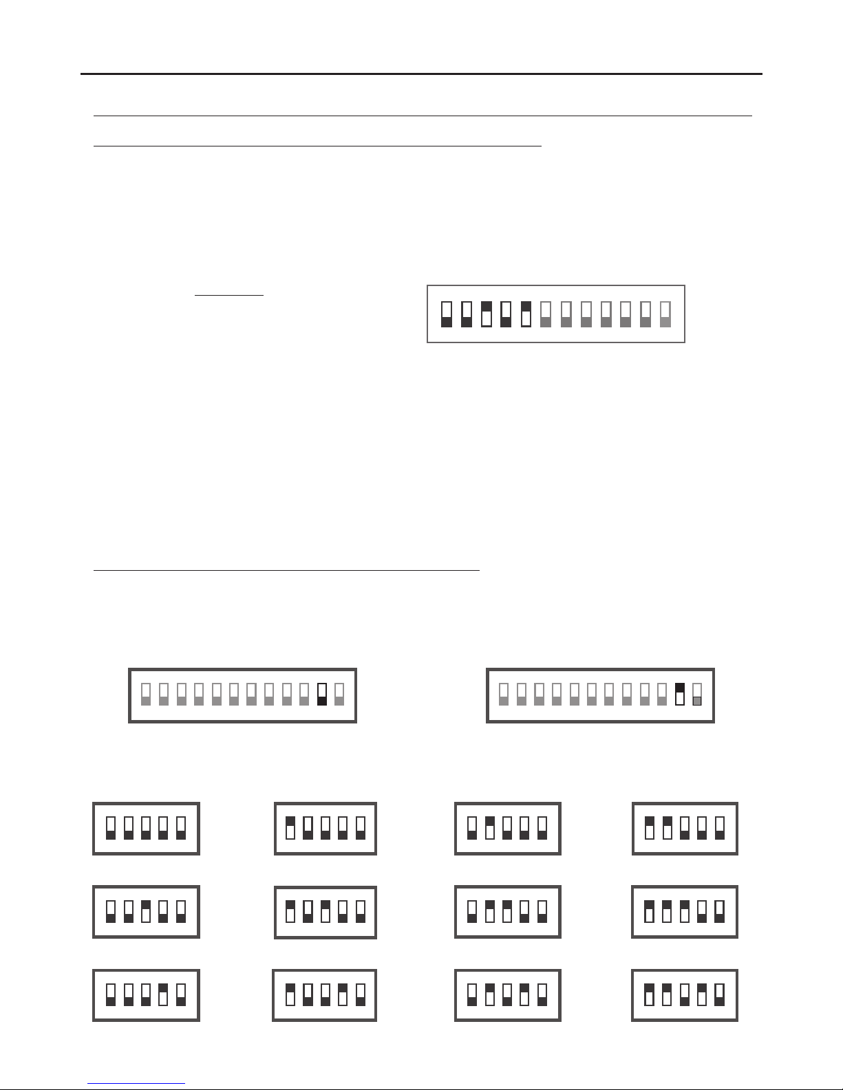
............................................................................................... .........4-5Setting address codes for the telephone ............
" octor ”.................................................................................................................................................5D mode function
............................................................................................................................... .......... 5Intercom function ................ .
Activation light function (stairs light)..............................................................................................................................5
......................................................................................................................... ..........6Setting the ring tones .................
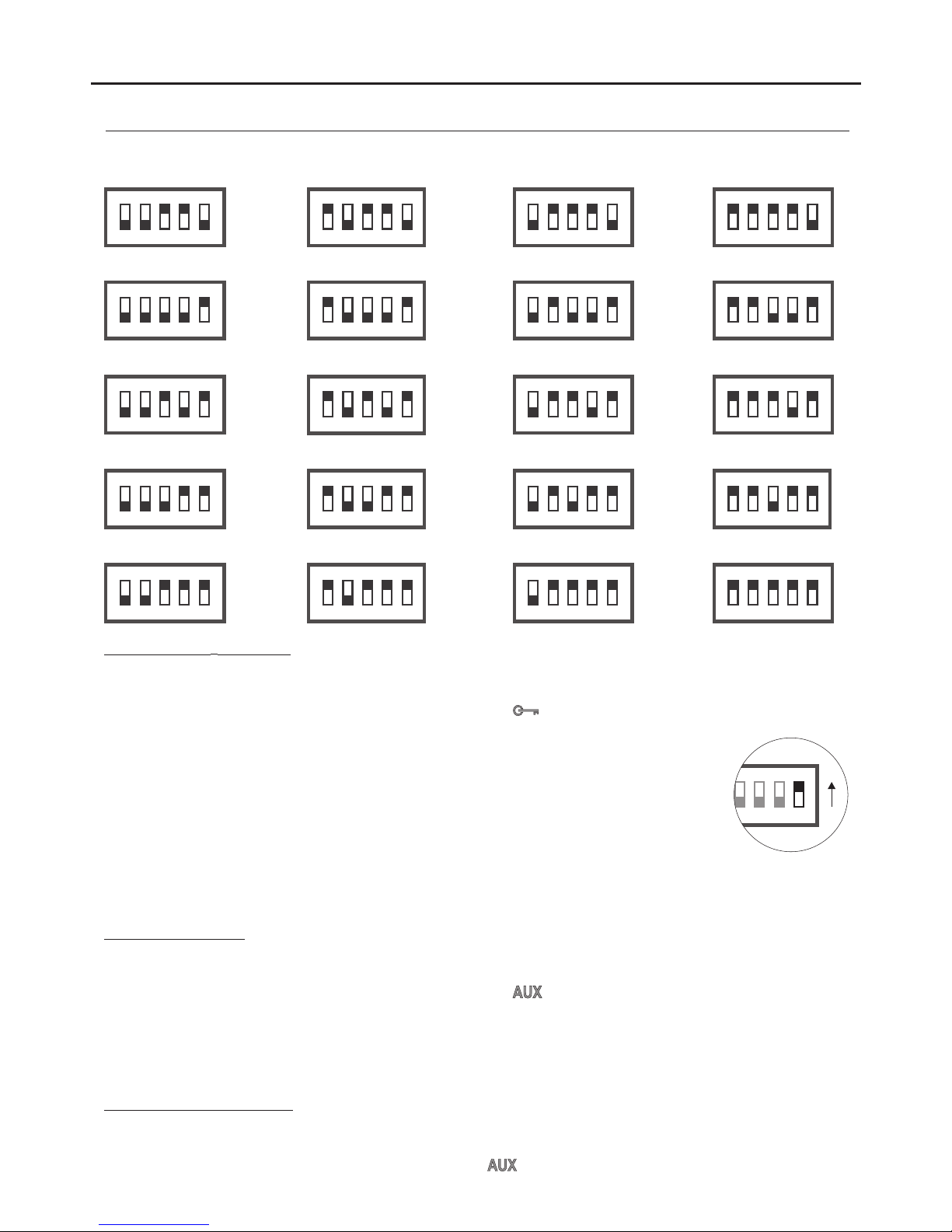
Installing the telephone...................................................................................................................................................7
Installation ............................................................................................................................. ............8diagrams ..............
Not s..............................................................................................................................................................................9e
T562 G 2B TELEPHONE
CHARACTERISTICS
- Telephone with simple installation (2 wire BUS ).without polarity
- Up to 4 telephones/monitors per apartment (master, slave 1, slave 2 and slave 3).
- Up to 32 apartments/telephones per installation.
- Completely private conversation.
- Call volume control (maximum, medium and mute).
- Input for calls from the apartment's door.
- Call repeater output (SAR-12/24).
- Different ring tones indicate the origin of the call (door panel, intercom or apartment door).
- Lock release push button1 .
- 2 / activation light (it requires of SAR-GB2 & SAR-12/24 modules) .Intercom/lock release push button
Important: The light function only with T562 telephones with V.03 or later.
- Push button for setting ring tones (inside the telephone).
- Dip switches for setting the telephone address (call code), master/slave, end of line and activating the “doctor mode”
(automatic door opening). Inside the telephone.