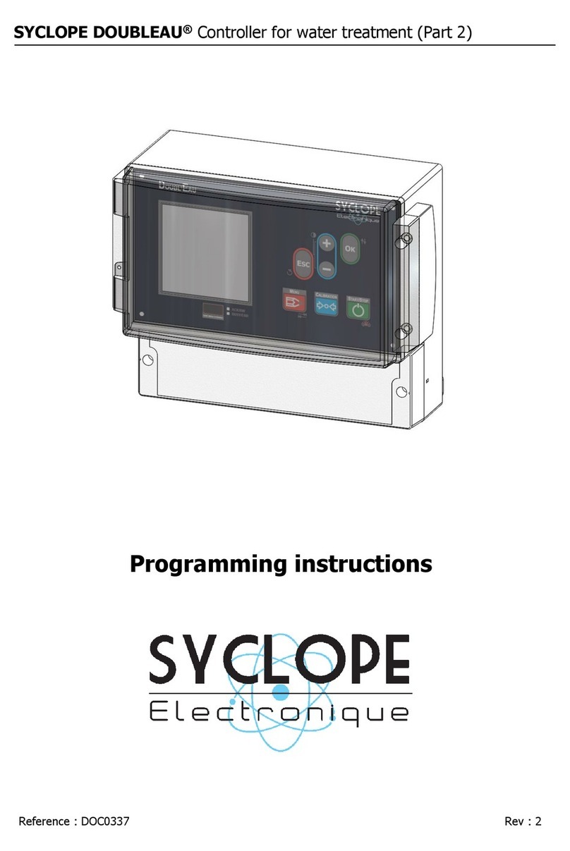
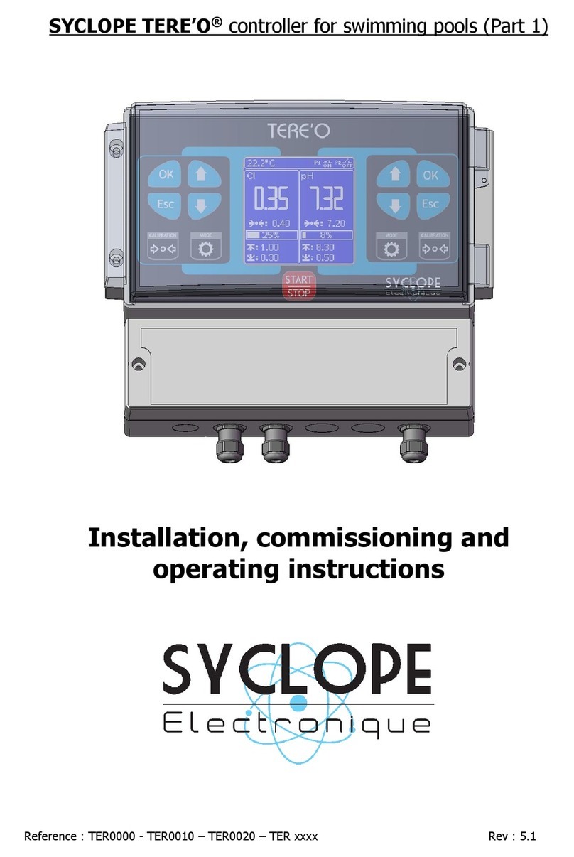
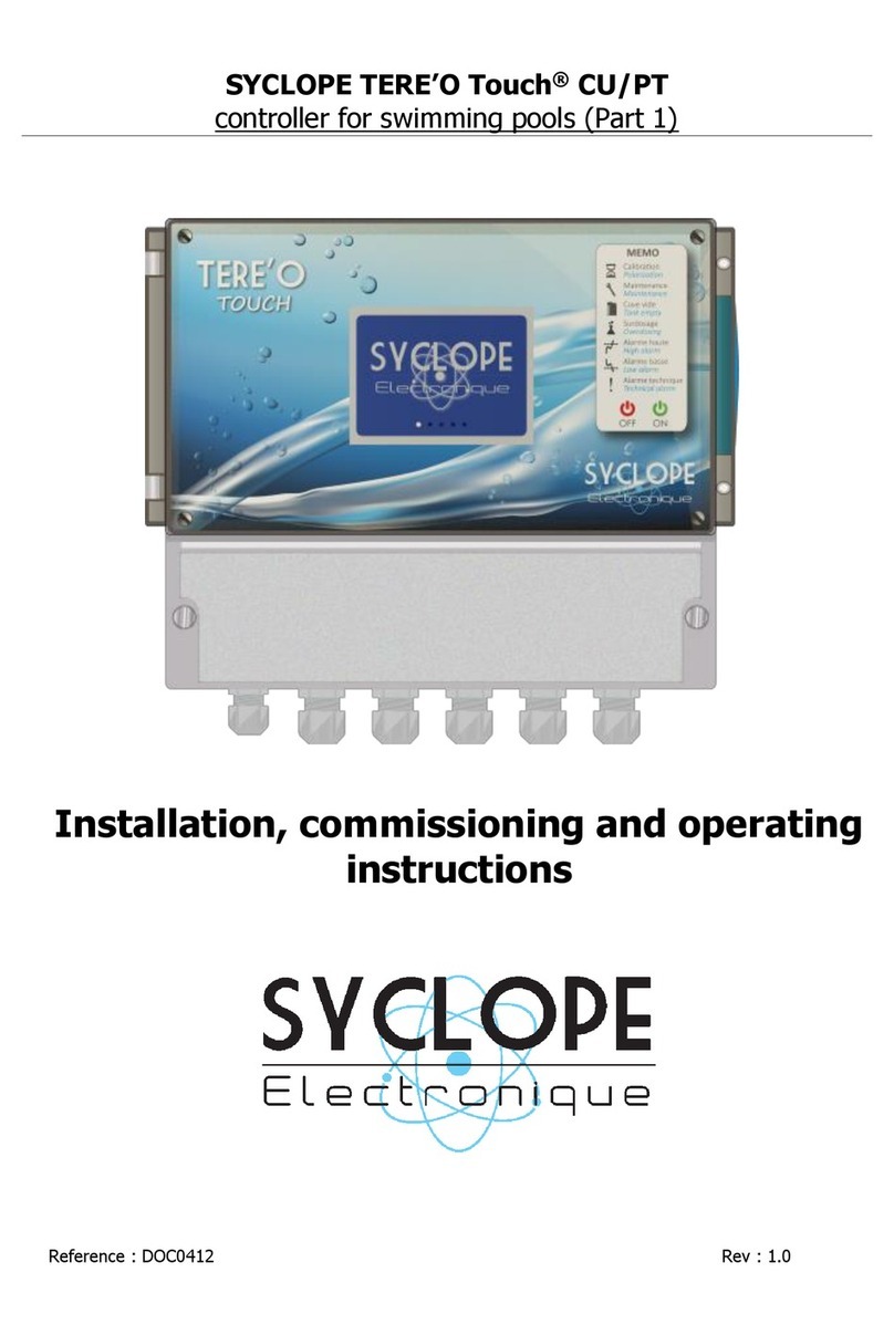
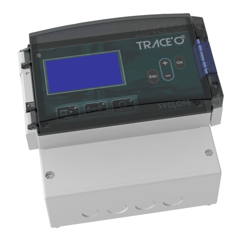
SYCLOPE INDIG'O Installation manual

Programming instructions
References : CEN0000, CEN0001 and CEN0005 Rev : 2
SYCLOPE INDIG’O
®
controller for
semi publics
swimming pool
s
( art 2
)

Generals information age 2/28
rogramming instructions of the SYCLOPE INDIG’O
®
arts of the general documentation
art 1 : Installation and starting instructions
art 2 : rogramming instructions
General details:
SYCLOPE Electronique 2 15
®
Notice of the 01/12/2015 Rev 2
Controller for semi publics swimming pools.
Range INDIG’O
®
art 2 : rogramming instructions
Editor:
SYCLOPE Electronique S.A.S.
Z.I. Aéropole pyrénées
Rue du Bruscos
64 230 SAUVAGNON - France –
Tel : (33) 05 59 33 70 36
Fax : (33) 05 59 33 70 37
Email : syclope@syclope.fr
Internet : http://www.syclope.fr
© 2015 by SYCLO E Electronique S.A.S.
Subject to modification
►

Content age 3/28
rogramming instructions of the SYCLOPE INDIG’O
®
I.
Use of the document ............................................................................................................. 4
1)
Symbols and signs .............................................................................................................. 4
2)
Storage and transport ......................................................................................................... 5
3)
ackaging .......................................................................................................................... 5
4)
Warranty ........................................................................................................................... 5
II.
Environment and safety procedures ........................................................................................ 6
1)
Use of the equipment ......................................................................................................... 6
2)
User obligations ................................................................................................................. 6
3)
Risk prevention .................................................................................................................. 6
4)
Identification and localization of the identification label ......................................................... 7
5)
Disposal and conformity ...................................................................................................... 8
III.
Human/Machine interface ...................................................................................................... 9
1)
Keyboard ........................................................................................................................... 9
2)
ermanent display, pictograms and messages .....................................................................10
3)
Alarms ..............................................................................................................................11
4)
Internal connections ..........................................................................................................12
IV.
Navigation into the menus ....................................................................................................13
1)
Accessing to the menus .....................................................................................................13
2)
Navigation into the Menu ...................................................................................................13
V.
Starting ...............................................................................................................................14
1)
Starting display .................................................................................................................14
2)
Adjust the contrast display .................................................................................................14
3)
Starting the control ...........................................................................................................14
VI.
Setting Menu .......................................................................................................................15
1)
Calibration of the sensor : Screen “Calibration” ...................................................................15
2)
Control settings : age “Control” ........................................................................................17
3)
Alarms configuration : age “Alarms” .................................................................................18
VII.
Configuration Menu ..............................................................................................................19
1)
Dosing mode : age “Dosage” ............................................................................................19
2)
Control cycle time : age “Control relay” .............................................................................21
3)
Range for 4-20 mA analog output : age “Analog output” ....................................................22
4)
Flow switch input : age “Flow switch” ...............................................................................22
5)
olarization time : age “Sensor” .......................................................................................22
6)
Output testing : age “Test” ..............................................................................................23
VIII.
Factory Menu .......................................................................................................................24
1)
Selection of the language...................................................................................................24
2)
Selection of the sensor ......................................................................................................24
3)
Selection of the range........................................................................................................25
IX.
CE Compliance certificate ......................................................................................................26
Use of the document age 4/28
rogramming instructions of the SYCLOPE INDIG’O
®
I. Use of the document
lease read this entire document before starting to install, adjusting or commissioning your controller
device, in order to ensure the safety of users, the processes and the equipment.
The information provided in this document must be strictly observed. SYCLO E Electronique S.A.S.
declines all responsibility in cases where failure to comply with the instructions of this documents is
observed.
The following symbols and pictograms will be used to facilitate reading and understanding of these
instructions.
● Information
► Action to be taken
Item of a list or catalogue
1) Symbols and signs
Identification of a continue voltage or current
Identification of an alternative voltage or current
rotective ground
Functional ground
Risk of injury or accident. Identify a warning concerning a potentially dangerous risk.
Documentation must be consulted by the user with each time the symbol is notified. If the
instructions are not respected, that presents a risk of death, physical injuries or property
damages.
Electric hazard. Identify a warning statement relative to a mortal electric danger. If the
instructions are not strictly respected, that implies an inevitable risk of physical injuries or
death.
Risk of incorrect operation or damage for the device.
Comment or particular information.
Recyclable element.

Use of the document age 5/28
rogramming instructions of the SYCLOPE INDIG’O
®
2) Storage and transport
It is important to store and transport your SYCLOPE INDIG’O
®
in its original packaging in
order to minimize risk of damage.
Furthermore, the package must be stored in an environment that is protected against humidity
and exposure to chemical products.
Environmental conditions for transport and storage:
Temperature: -10 °C to 70 °C
Air humidity: Maximum of 90% with no condensation
3) ackaging
The controller is delivered without electrical power cable.
The pre-holes of the box are drilled and equipped with according electrical glands in
compliance with I 65 level protection. Cables must be adapted to the electrical glands to
respect the level of protection.
Content of the packaging:
One analyser/controller SYCLOPE INDIG’O
®
Installation and starting instruction notice
rogramming notice
4) Warranty
The warranty is provided according to the terms of our general conditions of sale and delivery as long as
the following conditions are met:
Use of the equipment according to the instructions of this notice
No modifications of the equipment which may modify its behavior and no incorrect manipulation
Respect for the electrical safety conditions
Consumable material is no longer covered by the warranty when in use.

Environment and safety procedures
rogramming instructions of the SYCLOPE INDIG’O
®
II. Environment and safety procedures
lease:
Read this manual carefully before unpacking, installing or commissioning this equipment
Take into account all the hazards and recommended precautionary measures
Failure to respect these procedures can result in serious injury to users or damage the device.
1) Use of the equipment
The SYCLOPE INDIG’O
®
system has been designed to measure and control Chlorine, Bromine, pH,
Redox potential, Ozone, etc… by means of sensors and controls of suitable actuators in the context of
the possible uses described in this manual.
All other uses are considered to be non-conforming and must therefore be forbidden. SYCLO E
Electronique S.A.S. will not be responsible in any case for any damages that result from such
uses.
Any use of sensors or interfaces not-in conformity to the features defined in this handbook
must also be proscribed.
2) User obligations
The user undertakes not to allow its employees to work with the SYCLOPE INDIG’O
®
equipment
described in this manual unless they:
Are aware of the fundamental instructions relating to work safety and prevention of accidents
Are trained in the use of the device and its environment
Have read and understood these instructions, warnings and manipulation rules
3) Risk prevention
The installation and connection of the SYCLOPE INDIG’O
®
equipment should only be
performed by personnel specialized and qualified for this task.
The installation must comply with current safety standards and instructions!
Before switching on the controller or manipulating the relay outputs, remember always to cut
off the primary power supply!
Never open the controller when it is powered on!
Maintenance operations and repairs should only be performed by trained, specialized
personnel!
Take care when choosing the location for installing the equipment according to the
environment!
The SYCLOPE INDIG’O
®
electronic box should not be installed in a hazardous environment
and should be protected against splashing with water or chemical products. It should be
installed in a dry, well-ventilated location, isolated from corrosive vapours.

Environment and safety procedures
rogramming instructions of the SYCLOPE INDIG’O
®
Make sure that the chemical sensors used with this device correspond well to the chemicals
used. Refer to the individual technical note of each sensor. Chemistry of water is very complex,
in case of doubt, contact immediately our engineering service or your approved
installer/reseller.
Chemical sensors are sensitive elements using consumable parts. They must be supervised,
maintained and calibrated regularly using specific calibrator systems not-provided with this
equipment. In the event of defect, a surplus possible hazard of chemical injections can be
noted. In the doubt, a service contract must be taken near your reseller/installer or failing this
near our engineering services.
Contact your approved installer/reseller or our business service
for more information.
4) Identification and localization of the identification label
Label of the manufacturer articular risks. Read the notice
Model of the product roduct which can be recycled
Reference of the product Limitation of dangerous substances
Range of power supply EC certified
Values of the maximum current Country of origin
Classify protection Manufacturer square code
Identification of the manufacturer
Serial number
Identification label
1
2
3
9
4
5
6
8
1
1
1
2
7
1
4
1
0
1
3
INDIG’O
Ref
:
CEN
X
90
-
240VAC
50/
60Hz
www.syclo e.fr
Fabriqué en France
5,2
-
0,1
A
IP65
S/N: 13044217
1
2
3
4
5
6
7
8
9
1
0
1
1
1
2
1
3
1
4

Environment and safety procedures
rogramming instructions of the SYCLOPE INDIG’O
®
5) Disposal and conformity
The recyclable packaging of the SYCLOPE INDIG’O
®
equipment must be disposed of according to
current regulations.
Elements such as paper, cardboard, plastic or any other recyclable elements must be taken
to a suitable sorting center.
According to European directive 2002/96/EC, this symbol means that as of 12 August 2005
electrical appliances cannot be thrown out together with household or industrial
waste. According to current regulations, consumers within the European Union are required,
as of this date, to return their used devices to the manufacturer, who will take care of
disposing them at no extra expense.
According to European directive 2002/95/EC, this symbol means that the SYCLOPE
INDIG’O
®
controller is designed in compliance with the restrictions on hazardous substances
According to low-voltage directive (2006/95/EC) and the electromagnetic compatibility
directive (2004/108/EC), this symbol means that the device has been designed in
compliance with the previously cited directives

Human/Machine interface age 9/28
rogramming instructions of the SYCLOPE INDIG’O
®
III. Human/Machine interface
1) Keyboard
Display 128x128
Key “Menu” : Allow to go in the different menu or to valid a setting
Key “START/STO ” : Allow to start or stop the control. Allow also to acquit the alarms
Key “Esc” : Allow to return at the permanent display
Key “+” : Allow to increment a value or change a setting
Key “-” : Allow to decrement a value or change a setting
Chlore libre

Human/Machine interface age 10/28
rogramming instructions of the SYCLOPE INDIG’O
®
2) ermanent display, pictograms and messages
On this display, you can see all the working of your controller:
The measuring value
The set point
The dosing value
The parameter and his unit
The status of the relay
ictograms and messages for alarms
Visualisation
Signification
Value Measuring value and unity
arameter Showing the measured parameter
Status of relay Showing status of the relay. Checkmark means that relay is activated
Alarms Showing the actives alarms
M/A Indicator Showing status of the control. Auto or STOP
Set point Value to reach
Dosage Percent of control on the metering unit
Output Value sent to the PLC
REG
Free Cl
mg/l
Dosage : 58 %
Set point : 2,00 mg/l
Output : 4,187 mA
2,09
ALR
S
tatus
of the relay
Alarms pictograms
Measured parameter
Value and unit
Start/Stop indicator
Informations

Human/Machine interface age 11/28
rogramming instructions of the SYCLOPE INDIG’O
®
3) Alarms
Visualisation Signification Menu of
modification Value Action
Polarization time Configuration Menu
Sensor Page Time Stop dosing
Incorrect flow Configuration Menu
Flow switch Page NO or NC Stop dosing
Sensor Maintenance - - Calibration Limit
Low alarm threshold Settings Menu
Alarms Page Value Activate R1 relay
High alarm threshold Settings Menu
Alarms Page Value Activate R1 relay
Overdosing delay
Settings
Menu
Alarms Page Time Stop dosing
Activate R1 relay
Polarization or default
of the sensor - - Stop dosing
Sensor out of range
or short circuit - - Stop dosing
Bad connection or
sensor in default - - Stop dosing
olarization in progress
or defective sensor
I<3,7 mA
Sensor out of range
or
short circuit. I>20 mA
Disconnected
or
defec
tive sensor

Human/Machine interface age 12/28
rogramming instructions of the SYCLOPE INDIG’O
®
4) Internal connections
Reference: CEN0000 with 4-20 mA analog input
References: CEN0001 and CEN0005 with pH or OR input

Navigation into the menus age 13/28
rogramming instructions of the SYCLOPE INDIG’O
®
IV. Navigation into the menus
1) Accessing to the menus
The programming interface of the SYCLOPE INDIG’O
®
is based on 3 differents levels:
Setting Menu: to program the working settings such set point, alarms…
Configuration Menu: to configure the machine such flow switch, analog output…
Factory Menu: to configure the language, the parameter and the range
Each Menu contains several pages allowing to set or configure the unit.
This table describe the composition of each menu and how to reach them.
Menu Key Action Page
Setting
Simple ress
Calibration
Control
Alarms
Configuration
ress for 5 sec
Dosage
Control relay
Analog output
Flow switch
Sensor ( olarization)
Test
Factory
ress for 5 sec
during switching
on power
Language
Sensor (parameter)
Range
2) Navigation into the Menu
Once the Menu is reached:
: ermit to scroll the cursor and to valid a modification
: ermit to scroll the setting or the value selected

Starting
rogramming instructions of the SYCLOPE INDIG’O
®
V. Starting
1) Starting display
Once the controller is switched on, this screen appears.
Line Signification Setting Default value
Name Name of the product Indigo mA or mV Depend of the reference
ID Embedded software name INDMA or INDMV Depend of the reference
Version Embedded software version X.XX Depend of the reference
2) Adjust the contrast display
To adjust the contrast of the display, press on the arrow “TOP” or “BOTTOM” from the permanent
screen.
3) Starting the control
To start the control, press the key “START/STOP”
SYCLO E
Electronique
Starting…
Name
:
Indigo XX
ID : INDXX
Software version
: X.XX
Free Cl
mg/l
Dosage : 58%
2,09
Set point : 2,00 mg/l
REG
ALR
Output : 4,187 mA
64%
+
Free Cl
mg/l
2,09
REG
ALR
Dosage : 58%
Set point : 2,00 mg/l
Output : 4,187 mA
Free Cl
mg/l
2,09
Set point : 2,00 mg/l
REG
ALR
Dosage : 0,00%
Output : 4,187 mA

Setting Menu age 15/28
rogramming instructions of the SYCLOPE INDIG’O
®
VI. Setting Menu
The Setting Menu permit to set all the working parameter. ress the key “MENU” to reach this menu
and press again the key “MENU” to go over the 3 different screens of this level.
Menu Key Action Page
Setting
Simple press
Calibration
Control
Alarms
1) Calibration of the sensor : Screen “Calibration”
This screen allow to make two operations regarding the calibration of the sensor.
Buffer : to calibrate the sensor to the standard value measured with your reference device or a
buffer solution. Adjust the value with arrow keys “TOP” or “BOTTOM” then valid this value
pressing the “MENU” key.
Depending of the value set, the controller automatically adjust the slope or the offset.
Erasing : to reset the calibration and return to factory properties (Slope and offset). In this
screen, press the “MENU” key for 5 sec to do this operation.
Name Signification
Sensor Raw current or mV gives by the sensor without calibration
Raw value Raw value (in mg/l or mV) following the raw mA or mV signal
Buffer Value to set with the reference device or buffer solution
Slope Slope after calibration in mA/mg/l or in mV/pH
@Standard (Version mA) Correcting factor after calibration %
Offset (Version mV) Offset after calibration in mV
After calibrating, a message appears to tell you the calibration status.
Control
Alarms
2,09
Sensor:
6,506 mA
Calibration
Raw value:
2,08 mg/l
mg/l
Buffer:
Slope: 1,19 mA/mg/l
@Standard
:
100 %
Control
Alarms
6,99
Sensor: 0,5 mV
Calibration
Raw value:
6,99 (pH)
(pH)
Buffer
:
Offset: 0,0 mV
Slope: -59,1 mV/(pH)
Version 4
-
20 mA
Version pH
Version OR
Control
Alarms
+745
Sensor:
745 mV
Calibration
Raw value:
745 mV
mV
Buffer:
Offset: 0,0 mV

Setting Menu age 16/28
rogramming instructions of the SYCLOPE INDIG’O
®
Messages and signification after calibrating.
Message Signification Action Fig.
Slope OK Calibration correct. Slope changed Calibration done 1
Offset OK Calibration correct. Offset changed Calibration done -
Slope LIMIT
Check the probe
The calculated slope after calibration is
out of normal value. (Calculated
slope<> 33…..250% of standard slope)
Calibration done. Display of
the pictogram key of
maintenance on the
permanent screen
2+6
Offset LIMIT
Check the probe
The calculated slope after calibration is
out of normal value.
Calibration done. Display of
the pictogram key of
maintenance on the
permanent screen
-
Slope error
p=25…300%
(Version 4-20 mA)
The calculated slope after calibration is
out of acceptable values between 25
and 300%
Calibration refused 3
Offset error
Delta (max) = ±90 mV
(Version pH)
The calculated offset after calibration is
out of acceptable values Calibration refused
Calibration error
Delta (max) = ±70 mV
(Version OR )
The calculated offset after calibration is
out of acceptable values Calibration refused
Can’t be calibrated
during polarization
Impossible calibration during
polarization Calibration refused 4
Reset with factory
calibration
Reset calibration (slope and offset)
values Back to factory value 5
Control
Alarms Calibration
Sensor:
6,506 mA
Raw value:
2,08 mg/l
2,09
mg/l
Buffer:
Slope
:
1,19 mA/mg/l
@Standard : 100
%
Slope OK
Control
Alarms Calibration
Sensor:
6,506 mA
Raw value:
2,08 mg/l
2,09
mg/l
Buffer:
@Standard : 100
%
Slope : 1,19 mA/mg/l
Slope LIMIT
Check the probe
Control
Alarms
Calibration
Sensor:
6,506 mA
Raw value: 2,08 mg/l
2,09
mg/l
Buffer:
@Standard : 100
%
Slope : 1,19 mA/mg/l
Slope error
p=25…300%
Control
Alarms
Calibration
Sensor: 6,506 mA
Raw value: 2,08 mg/l
2,09 mg/l
Buffer
:
@Standard : 100
%
Slope : 1,19 mA/mg/l
Reset with
factory calibration
Free Cl
mg/l
2,09
REG
ALR
Dosage : 58%
Set point : 2,00 mg/l
Output : 4,187 mA
Control
Alarms Calibration
Sensor: 6,506 mA
Raw value: 2,08 mg/l
2,09 mg/l
Buffer:
@Standard : 100
%
Slope : 1,19 mA/mg/l
Can’t be calibrated
during polarization
1
2
3
4
5
6

Setting Menu age 17/28
rogramming instructions of the SYCLOPE INDIG’O
®
2) Control settings : age “Control”
This page allow you to set:
The set point: value to control in your water
The Xp value: value for the proportional action on the metering unit
Name Signification Setting range Default value
Set point Set point value for
control
4-20 mA : 10% to 85%*
pH : 2 to 12
OR : 300 à 850
4-20 mA : 20%*
pH : 7,2
OR : 460 mV
Xp Value of the
proportional action
4-20 mA : 10% to 500%*
pH : 0,1 to 70
OR : 1 to 100
4-20 mA : 10%*
pH : 7,2
OR : 460 mV
(*) : In % of the measured full scale set for the sensor
Details :
-Setpoint : Means value to be reached and stabilized along processing time.
-X value : Difference between the measuring value and the setpoint for which the regulation is at the
maximum. (Controlling value* at 100%).
*Controlling value : It represent the proportional action on the dosing unit (For example, a dosing pump)
to reach the setpoint. This value is displayed on the main screen and call “Dosage : xx %” (See
picture)
Example : Setpoint is 2 mg/l and Xp is 1 mg/l
If difference is 1.5 (> to 1) then Controlling value = 100%
If difference is 1.0 (= to 1) then Controlling value = 100%
If difference is 0.5 (< to 1) then Controlling value = 50%
If difference is 0.25 (< to 1) then Controlling value = 25%
Free Cl
mg/l
1,50
REG
ALR
Dosage : 50%
Setpoint : 2,00 mg/l
Output : 6,400 mA
Alarms
Calibration
Control
2,00
mg/l
Set point :
1,00
mg/l
Xp
:
Alarms
Calibration
C
ontrol
7,20
(pH)
Set point
:
0,30
(pH)
Xp :
Alarms
Calibration
Control
460
mV
Set point :
30
mV
Xp :
Version 4-20 mA Version pH Version OR

Setting Menu age 18/28
rogramming instructions of the SYCLOPE INDIG’O
®
3) Alarms configuration : age “Alarms”
This page allow you to define :
Upper alarm threshold : value for the upper alarm threshold with activation of the Alarm relay
after overpassing the value
Lower alarm threshold : value for the lower alarm threshold with activation of the Alarm relay
after overpassing the value
Overdosing delay : Maximum delay (in sec) to reach the setpoint. If overpassing of this delay,
activation of the Alarm relay + stop control + display of the pictogram on the main screen
Name Signification Setting range
Default
value Action
Upper
threshold Upper threshold value
4-20 mA : 2 to 100%*
pH : 0,2 to 14
OR : -980 to 1000
4-20 mA : 40 %*
pH : 7,70
OR : 850
Alarm activation
Lower
threshold Lower threshold value
4-20 mA : 0% to 98%*
pH : 0 to 13,8
OR : -1000 to 980
4-20 mA : 10 %
pH : 6,80
OR : 300
Alarm activation
Overdose Maximum dosing delay
before stopping control 0……9999 s 0 s Alarm activation
Stop control
(*) : Expressed in % of the measuring range
REG
Free Cl
mg/l
Dosage : 0,00%
Setpoint : 2,00 mg/l
Output : 10,57
mA
4,10
ALR
REG
pH
pH
Dosage : 0,00%
Setpoint : 7,20 pH
Output : 11,43
mA
6,50
ALR
REG
pH
pH
Dosage : 0,00%
Setpoint : 7,20 pH
Ouput : 12,57 mA
7,50
ALR
Upper Alarm
Overdosing
Lower Alarm
Alarms ation Control
4,00
mg/l
Upper
:
1,00
mg/l
Lower
:
0
s
Overdose :
Version 4
-
20 mA
Version pH
V
ersion OR
ation
850
mV
Upper
:
300
mV
Lower
:
0 s
Overdose
:
ation
7,70
(pH)
Upper :
6,80
(pH)
Lower :
0
s
Overd
ose
:
Ala
rms
Control
Alarms
Control

Configuration Menu age 19/28
rogramming instructions of the SYCLOPE INDIG’O
®
VII. Configuration Menu
The Configuration Menu allow you to configure the machine. Keep pressing during 5 sec the “MENU”
key to access to this level. Then, press again the Menu key to drive into the different steps.
Menu Key Action Page
Configuration
ress during 5 sec
Dosage
Control relay
Analog output
Flow switch
Sensor ( olarization)
Test
1) Dosing mode : age “Dosage”
According to the version of the product, this page allow to set :
Additional load : This value, expressed in %, permit to keep a minimum dosing action even
once the setpoint reached.
Then, according to the version of the machine :
In 4-20 mA version, the dosing mode : roportional mode ( rop.) or On/Off with hysteresis
(Hyst.)
In pH version, the direction : Direction of the dosing (Acid or pH-) or (Alkali or ph+)
In OR version, the direction : Oxidant or Reducer
The direction in the 4-20 mA version is always a rising action. The value should be below the
setpoint to have an action of the dosing unit.
In the 4-20 mA version, if the Hysteresis dosing mode is set, the control range should be set
in the “Control” page of the Setting Menu instead of the Xp value in proportional dosing mode.
This value is also expressed in the measuring unity (For example, mg/l).
Dosage
Control relay An
0
Additional
load
:
%
Hyst.
Dos
age
mode
:
rop.
Dosage Control relay An
0
Additional
load
:
%
Oxidant
Direction :
Reducer
Dosage
Control relay An
0
Additional
load
:
%
Direction
:
A
cid
(pH
-
)
Alkali
(pH+)
Version 4-20 mA Version pH Version OR

Configuration Menu age 20/28
rogramming instructions of the SYCLOPE INDIG’O
®
Name Signification
Setting
range
Default
value
Additional load Minimum dosing action 0 to 30 % 0 %
Dosage mode roportional control or Hysteresis
threshold rop. or Hyst. rop.
Direction
Version pH Control direction Acid or Alkali Acid
Direction
Version Redox Control direction Reducer or
Oxidant Oxidant
Control chart according to the dosing mode set roportional or Hysteresis.
roportional dosing mode
Setpoint
2,0
1,5
1,0
0,5
Controlling
value in %
100
Setpoint : 2,00 mg/l
Xp : 1 mg/l
Value in
mg/l
T
ime
0
75
50
25
0 Time
Hysteresis threshold mode
Setpoint
2,0
1,5
1,0
0,5
Controlling
value in %
100
Setpoint : 1,50 mg/l
Hyst. : 1 mg/l
Value in
mg/l
Temps
0
75
50
25
0
T
ime
Low Threshold
Hysteresis
High Threshold
Hysteresis
Other manuals for INDIG'O
1
Table of contents
Other SYCLOPE Controllers manuals

SYCLOPE
SYCLOPE TRACE'O User manual

SYCLOPE
SYCLOPE DOUBLEAU Installation manual

SYCLOPE
SYCLOPE ALTICE'O Use and care manual

SYCLOPE
SYCLOPE EVASION Installation manual

SYCLOPE
SYCLOPE TERE'O Touch CU/PT Guide

SYCLOPE
SYCLOPE UNIS'EAU How to use

SYCLOPE
SYCLOPE ODISEA Installation manual

SYCLOPE
SYCLOPE TERE'O User manual

SYCLOPE
SYCLOPE INDIG'O How to use