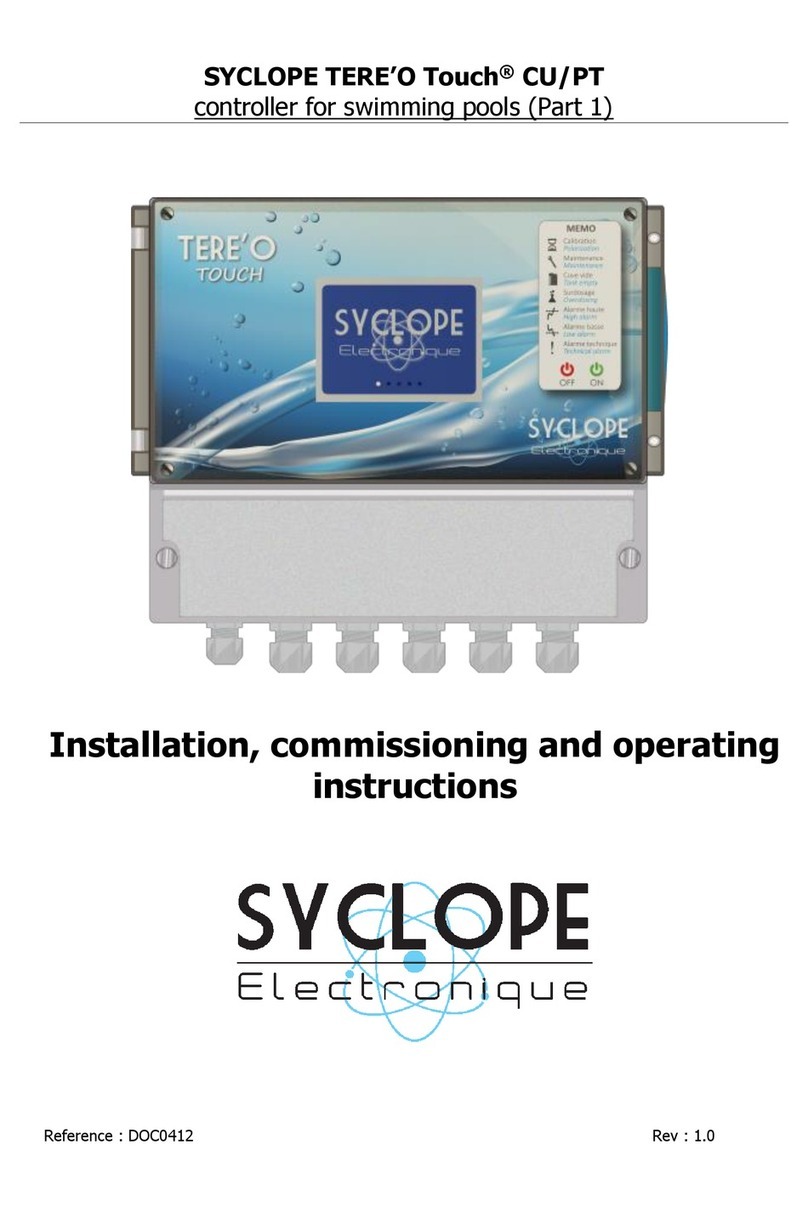
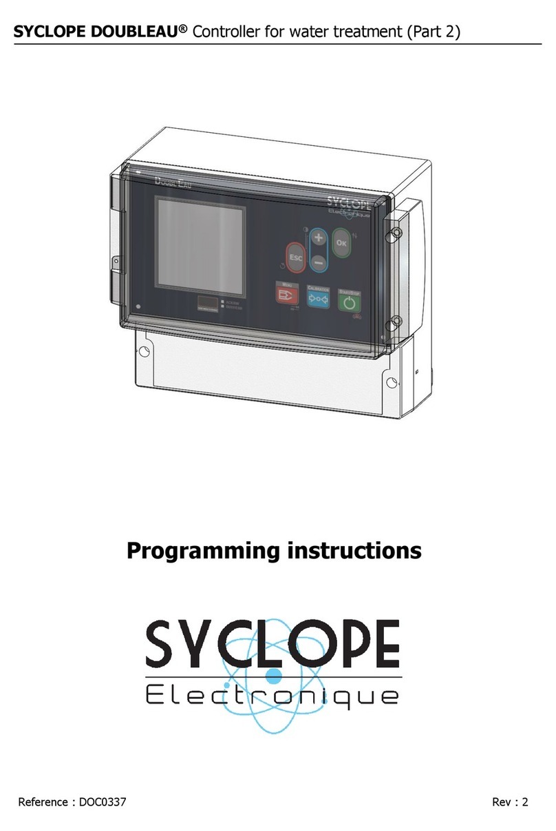
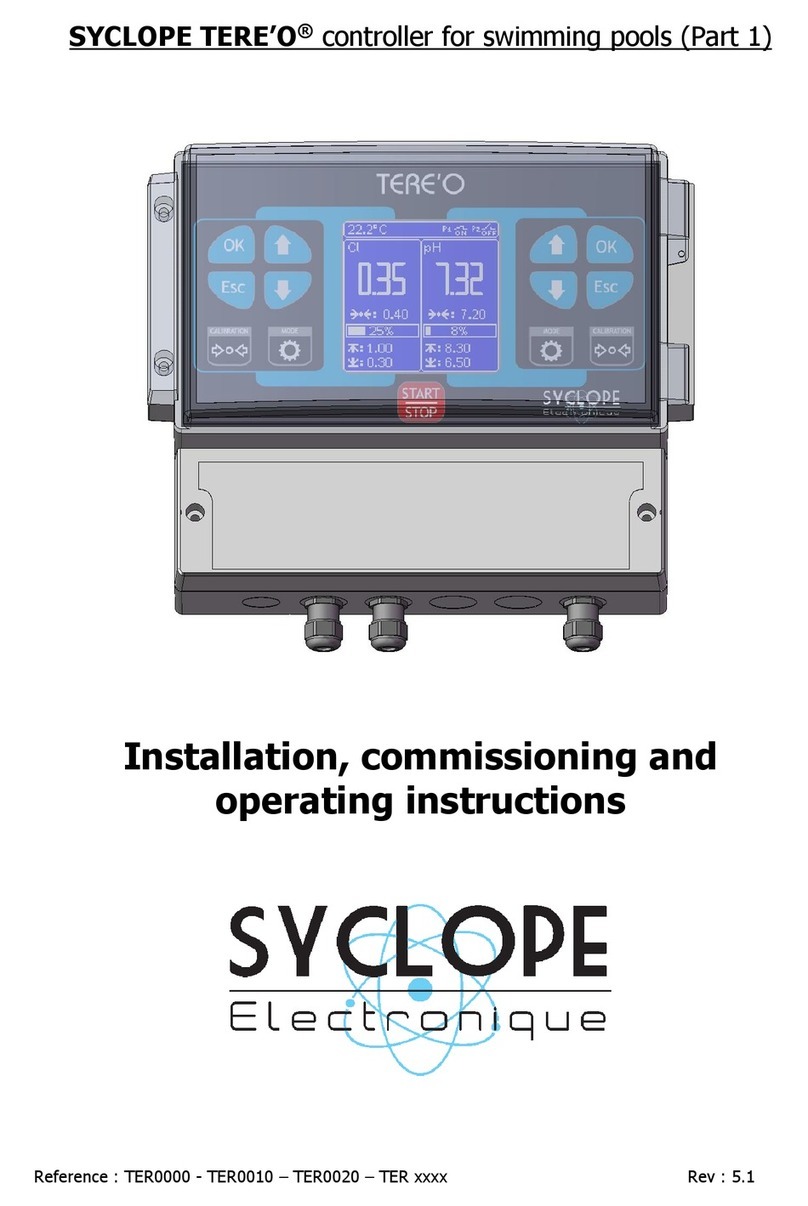
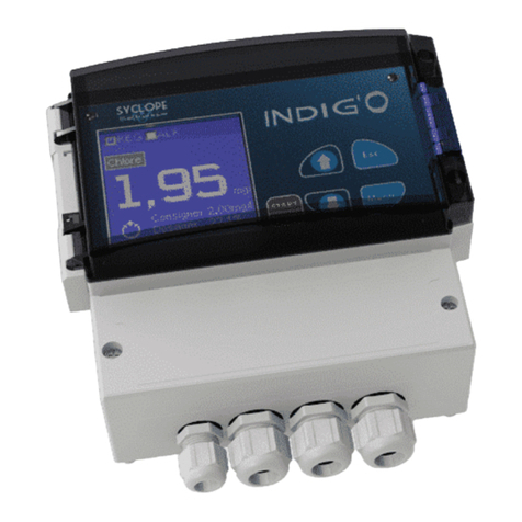
SYCLOPE TRACE'O User manual

Programming instructions
Reference : CTR 0001 Rev : 2
SYCLOPE TRACE’O®: Universal controller for trace detection (Part 2)

General informations Page 2/60
Programming manual of SYCLOPE TRACE’O®
Parts of the general documentation
Part 1 : Installation and starting instructions
Part 2 : Programming instructions
Part 3 : Communications instructions
General information :
SYCLOPE Electronique 2016®Manual of 2016, February 20th Rev 2
Universal controller for standard and trace measurement.
Product line TRACE’O®
Part 2 : Programming instructions (Ref. DOC0322)
Editor :
SYCLOPE Electronique S.A.S.
Z.I. Aéropole pyrénées
Rue du Bruscos
64 230 SAUVAGNON - France
Tel : (33) 05 59 33 70 36
Fax : (33) 05 59 33 70 37
Email : syclope@syclope.fr
Internet : http://www.syclope.fr
© 2015 - 2016 by SYCLOPE Electronique S.A.S.
Subject to modification
►

Summary Page 3/60
Programming manual of SYCLOPE TRACE’O®
Summary
I. Use of the document ............................................................................................................. 4
II. Environment and safety procedures........................................................................................ 5
1) Use of the equipment ......................................................................................................... 5
2) User obligations ................................................................................................................. 5
III. Introduction to the human-machine interface (HMI) ................................................................ 6
1) Display and control keypad ................................................................................................ 6
2) Internal connections ........................................................................................................... 7
3) Terminal block connections ................................................................................................. 7
IV. Structure and index of the programming menus...................................................................... 8
1) Structure of the menus....................................................................................................... 8
2) Tree structure and index of programming ............................................................................ 8
V. Main menu............................................................................................................................ 9
1) Accessing user menu .......................................................................................................... 9
2) Changing the Language ...................................................................................................... 9
3) Setting real time and date..................................................................................................10
4) Services of the controller ...................................................................................................10
VI. User Menu ...........................................................................................................................14
1) Accessing the Specialist Menu ............................................................................................14
2) User access code...............................................................................................................15
3) Calibration of parameter ....................................................................................................15
4) Setting points....................................................................................................................17
5) Programming cycles of polarisation times............................................................................19
6) Programming technical alarm thresholds.............................................................................20
7) Programming analogical outputs ........................................................................................21
8) Programming the interval of printing ..................................................................................22
9) Management of the display ................................................................................................22
VII. Specialist Menu ....................................................................................................................25
1) Specialist code ..................................................................................................................26
2) Selecting parameters.........................................................................................................26
3) Type of controls ................................................................................................................29
4) Using and programming relays...........................................................................................36
5) Analogical outputs assignment ...........................................................................................41
6) Polarization/depolarization cycles .......................................................................................42
7) Hold function ....................................................................................................................46
8) Maintenance function ........................................................................................................46
9) Flow function ....................................................................................................................47
10) Flow switch function (Flsw) ............................................................................................48
11) Communication .............................................................................................................49
12) Factory settings .............................................................................................................53
VIII. Start the calculations and dosages.........................................................................................54

Use of the document Page 4/60
Programming manual of SYCLOPE TRACE’O®
I. Use of the document
Please read this entire document before starting to install, adjust or commission your controller device,
in order to ensure the safety of swimmers, users and equipment.
The information provided in this document must be strictly observed. SYCLOPE Electronique S.A.S.
declines all responsibility in cases where failure to comply with the instructions of this documents is
observed.
The following symbols and pictograms will be used to facilitate reading and understanding of these
instructions.
●Information
►Action to be taken
Item of a list or catalogue
Risk of injury or accident. Identify a warning concerning a potentially dangerous risk.
Documentation must be consulted by the user with each time the symbol is notified. If the
instructions are not respected, that presents a risk of death, physical injuries or property
damages.
Electric hazard. Identify a warning statement relative to a mortal electric danger. If the
instructions are not strictly respected, that implies an inevitable risk of physical injuries or
death.
Risk of incorrect operation or damage for the device.
Comment or particular information.
Recyclable element

Environment and safety procedures Page 5/60
Programming manual of SYCLOPE TRACE’O®
II. Environment and safety procedures
All the programming procedures you will do with the SYCLOPE TRACE’O®controller will
modify his current working. Therefore, it is strongly recommended to read this entire manual
before any change. Only specialized or recommended technical personal must be authorized
to program the SYCLOPE TRACE’O®controller.
Please:
Read this manual carefully before unpacking, installing or commissioning this equipment
Take into account all the hazards and recommended precautionary measures
Failure to respect these procedures can result in serious injury to users or damage the device.
1) Use of the equipment
The SYCLOPE TRACE’O®system has been designed to measure and control physico-chemical
parameters by means of sensors and controls of suitable actuators in the context of the possible uses
described in this manual.
All other uses are considered to be non-conforming and must therefore be forbidden.
SYCLOPE Electronique S.A.S. will not be responsible in any case for any damages that result
from such uses.
Any use of sensors or interfaces not-in conformity to the features defined in this handbook
must also be proscribed.
2) User obligations
The user undertakes not to allow its employees to work with the SYCLOPE TRACE’O®equipment
described in this manual unless they:
Are aware of the fundamental instructions relating to work safety and prevention of accidents
Are trained in the use of the device and its environment
Have read and understood these instructions, warnings and manipulation rules.

Intoduction to the human-machine interface (HMI) Page 6/60
Programming manual of SYCLOPE TRACE’O®
III. Introduction to the human-machine interface (HMI)
1) Display and control keypad
Backlit 64x128 display with white writing on blue background
Menu key: To allow accessing to the programming menu (red LED)
Calibration key: To allow the sensors, to be directly calibrated (Orange Led).
STOP/START key: To allow starting or stopping of the processes (green LED)
Esc key: To allow to delete the settings or to come back in the programming menus
OK key: To allow to validate the settings or to move forward in the programming menus
Plus key: To allow scrolling through the menus and to increase a value
Minus key : To allow scrolling through the menus and to decrease a value
1
1

Internal connections Page 7/60
Programming manual of SYCLOPE TRACE’O®
2) Internal connections
F1 : General fuse (Time-lag 315 mA miniature Glass type)
Terminal block (See below)
Modem phone line standard connector (RTC)
Location for socket modem (Phone, GSM, WIFI or Ethernet - optional)
Serial printer connector (RS232C)
Ribbon cable connector to the top card.
3) Terminal block connections
1
2
F1
3
4
5
5
1
2
3
4
5
6

Structure and index of the programming menus Page 8/60
Programming manual of SYCLOPE TRACE’O®
IV. Structure and index of the programming menus
1) Structure of the menus
The programming structure of the SYCLOPE TRACE’O®controller is organized in three levels of
menu with the possibility to manage each level by a protection access code. From the simple user
level to the specialist level, the controller gives access progressively to fundamental functions of his
operation and thus, to the human safety and water treatment warranties.
Main menu : For the normal operations and simple calibrations
User menu : For the programming of basic elements as setpoints, thresholds, etc …
Specialist menu : For the complete configuration or modification of the controller.
For accessing to the roll-up menu, the function “START/STOP” must be on “STOP” position
(Green DEL off)
Press the " Menu " key …
The red DEL into the “Menu” key light-up …
Using the navigation keys, validate the successive menus …
Each level offers a various menu of functions to be programmed.
2) Tree structure and index of programming
Menu
Function
Page
Main
Accessing user menu
9
Changing the language
9
Adjusting real time clock
10
Services (Unlocked in the specialist menu)
10
User
Accessing specialist menu
14
User code
15
Calibrations
15
Setpoints
18
Timer polarization cycles
(Available in « Trace detection » mode)
19
Technical alarms
20
Analogical outputs
21
Printer output
22
Display management
22
Specialist
Specialist code
26
Select parameters
26
Type of controls
29
Relay functions
36
Analogical functions
41
Polarization cycles
(Available in « Trace detection » mode))
42
« Hold » Function
46
Maintenance Function
46
Flowrate Function
47
« Flow-switch » Function
48
Communication
49
Factory settings
53
Main Menu
User Menu
Specialist menu

Main menu Page 9/60
Programming manual of SYCLOPE TRACE’O®
V. Main menu
For entering into the Main menu, press on key . Now, you have access to the first level of
the menus.
For accessing to the first roll-up menu, the function “START/STOP” must be on “STOP”
position (Green DEL off)
1) Accessing user menu
If a code was registered :
Enter the access code for entering into the technician menu.
2) Changing the Language
Select the corresponding language.
Access code...: 0...
_ >> USER MENU <<_
Specialist menu
User code
Calibrations
Setting points
Technical alarms
Analog. Outputs
Printer output
_ >> MAIN MENU <<_
User menu
Langue/Sprache/Taal
Setting real time
Services
* TRACEO V1.00 *
Sn: xxxxxxxxx
_ >> MAIN MENU <<_
User menu
Langue/Sprache/Taal
Setting real time
Services
* TRACEO V1.00 *
Sn: xxxxxxxxx
_ >> MAIN MENU <<_
Langue/Sprache/Taal
French
English
German
Spanish
Italian
Portuguese
_ >> MAIN MENU <<_
User menu
Langue/Sprache/Taal
Setting real time
Services
* TRACEO V1.00 *
Sn: xxxxxxxxx
_ >> MAIN MENU <<_
User menu
Langue/Sprache/Taal
Setting real time
Services
* TRACEO V1.00 *
Sn: xxxxxxxxx

Main menu Page 10/60
Programming manual of SYCLOPE TRACE’O®
3) Setting real time and date
Adjust real time clock and date
4) Services of the controller
This function allows to realize the maintenance of the controller. It is possible to simulate all inputs
and outputs for controlling the normal working. This function is activated after his validation into the
specialist menu.
When the maintenance function is activated, all signals generated by the sensors are displayed and
allow you to estimate the quality and the good working of each of them.
a) Unlock and lock the maintenance function
Setting real time _
Year:15 Month:02
Date:19 Day:04
Time....:17H14min
_ >> MAIN MENU <<_
User menu
Langue/Sprache/Taal
Setting real time
Services
* TRACEO V1.00 *
Sn: xxxxxxxxx
_ >> MAIN MENU <<_
User menu
Langue/Sprache/Taal
Setting real time
Services
* TRACEO V1.00 *
Sn: xxxxxxxxx
_ >> USER MENU <<_
Specialist menu
User code
Calibrations
Setting points
Technical alarms
Analog. Outputs
Printer output
_ >> MAIN MENU <<_
User menu
Langue/Sprache/Taal
Setting real time
Services
* TRACEO V1.00 *
Sn: xxxxxxxxx
>> SPECIALIST MENU <<_
Specialist code
Select. Parameters
Type of controls
Relays functions
Analog. Functions
Hold function
Maintenance state
>> SPECIALIST MENU <<_
Specialist code
Select. Parameters
Type of controls
Relays functions
Analog. Functions
Hold function
Maintenance state
pH
K: A - - - CAD @14:44
->
.
<- : 28.0 ->
.
<- : 7.40
24.1
°C
- - - -
12.3 mA
2.5mA

Main menu Page 11/60
Programming manual of SYCLOPE TRACE’O®
Select “Activated”, then validate.
b) Enter into the Maintenance menu
The function of “Test Modem” is only available when a communication modem is connected
internally.
c) Test of the relays
Use the +/- keys for activating or disabling the selected relay. (1)=activated and
(0)=Disabled. Use the OK key for navigating between each relay.
When activated (1), check if the corresponding relay is really “on”.
►Repeat the same procedure for each relay.
>> SPECIALIST MENU <<_
Maintenance function
Disabled...
Activated...
_ >> MAIN MENU <<_
User menu
Langue/Sprache/Taal
Setting real time
Services
* TRACEO V1.00 *
Sn: xxxxxxxxx
_ >> MAIN MENU <<_
User menu
Langue/Sprache/Taal
Setting real time
Services
* TRACEO V1.00 *
Sn: xxxxxxxxx
_ >> MAIN MENU <<_
Services
Tests relays
Tests analog.
Printer
Modem
_ >> MAIN MENU <<_
Services
Tests relays
Tests analog.
Printer
Modem
Relays simulation _
Ka:0 Kb:0
Kc:0 Kd:0

Main menu Page 12/60
Programming manual of SYCLOPE TRACE’O®
d) Analogical Simulation
Use the +/- keys for programming the desired value.
Use the OK key for navigating between each digit and between each output.
Check with an amperometric measurement tool, if the same value is immediately
onto the corresponding analogical output.
e) Printer test
►Check if “Printer test” is really printed.
For executing the printer test, you must use the special serial cable for RS232C serial
printer. (Réf. câble CBI0000)
f) Test of the Modem
Case of phone line modem
The phone line modem doesn’t provide information.
Case of GSM or GPRS modem
As soon as the modem is activated and recognized, the following informations appear:
► If the modem cannot connect the network …
_ >> MAIN MENU <<_
Services
Tests relays
Tests analog.
Printer
Modem
Analog. Simulation _
Ia Output :00.0 mA
Ib Output :00.0 mA
_ >> MAIN MENU <<_
Services
Tests relays
Tests analog.
Printer
Modem
_ >> MAIN MENU <<_
Printing...
_ MODEM TEST _
PIN :
Network:
Signal :
_ MODEM TEST _
PIN : Error
Network: Error
Signal : Error

Main menu Page 13/60
Programming manual of SYCLOPE TRACE’O®
► If the modem is connected to the network …
Case of ETHERNET modem
As soon as the modem is activated and recognized, the following informations appear:
► If the Modem cannot connect the network …
► If the modem is connected to the network …
Cas of WiFi Modem
As soon as the modem is activated and recognized, the following informations appear:
► If the Modem cannot connect the network …
► If the modem is connected to the network …
_ MODEM TEST _
PIN : In progress
Network:
Signal.:
_ MODEM TEST _
PIN : OK
Network: OK
Signal.: OK
__
_ MODEM TEST _
STATE: In progress
IP...: In progress
_ MODEM TEST _
STATE: Error
IP...: 0.0.0.0
_ MODEM TEST _
STATE: In progress
IP...: In progress
_ MODEM TEST _
STATE: CONNECTED
IP...: 168.192.3.2
_ MODEM TEST _
STATE: In progress
IP...: In progress
Signal.: In progress
_ MODEM TEST _
STATE: INITIALIZING
IP : 0.0.0.0
Signal.: Erreur
_ MODEM TEST _
STATE: In progress
IP...: In progress
Signal.: In progress
_ MODEM TEST _
STATE: CONNECTED
IP...: 168.192.3.2
Signal.: Good
__

User Menu Page 14/60
Programming manual of SYCLOPE TRACE’O®
VI. User Menu
This menu allows to program or to modify all basic functions such as:
User access code
Calibrations
Set points
Polarization cycle timers (Only if « Trace detection » function is activated))
Technical alarms
Analogical outputs
Printer port
Display environment
Accessing to the User Menu …
If a User access code was registered :
Enter the corresponding code to access to the user menu.
1) Accessing the Specialist Menu
If a specialist access code was registered :
_ >> USER MENU <<_
Specialist menu
User code
Calibrations
Setting points
Technical alarms
Analog. Outputs
Printer output
_ >> MAIN MENU <<_
User menu
Langue/Sprache/Taal
Setting real time
Services
* TRACEO V1.00 *
Sn: xxxxxxxxx
Access code...: 0...
_ >> MAIN MENU <<_
User menu
Langue/Sprache/Taal
Setting real time
Services
* TRACEO V1.00 *
Sn: xxxxxxxxx
_ >> USER MENU <<_
Specialist menu
User code
Calibrations
Setting points
Technical alarms
Analog. Outputs
Printer output
>> SPECIALIST MENU <<_
Specialist code
Select. Parameters
Type of controls
Relay functions
Analog. Functions
Hold function
Maintenance state
Access code...: 0...
_ >> USER MENU <<_
Specialist menu
User code
Calibrations
Setting points
Technical alarms
Analog. Outputs
Printer output

User Menu Page 15/60
Programming manual of SYCLOPE TRACE’O®
2) User access code
For modify the User Code or to cancel it, proceed as follow:
Use the +/- and « OK » keys to enter
the new User Code.
For cancelling the User code, repeat the same procedure and enter the “0000” value !
3) Calibration of parameter
The complete calibration procedure is described in this paragraph.
a) Calibration of analogical parameters
Both analogical parameters (Main and auxiliary) can be adjusted by the same manner.
For a complete method, it is necessary to use special calibration reagents.
According to the reagent, the following procedures are done :
•pH=7 solution for “zero” of the pH electrode
•pH=4 solution for determining “slope” of the pH electrode
•465mV solution (or another one) for determining the « slope » of the Redox electrode
(Zero of the Redo electrode is generally not necessary)
•For the other sensors, it is strongly recommended to calibrate the sensor into the
working measuring cell with the normal flowrate before any calibration procedure.
This procedure must be executed when real value has been determined by manual
procedure with a special photometric tool.
In this menu, three procedures can be executed for modifying the measurement of the sensor:
Zero (or pH=7) : For fixing the Zero of the sensor if necessary !
Slope (or gain) : For calibrating the sensor to the real measured value.
Clearing : For erasing all previous values (Default factory setting)
According to the physical selected parameters, the choice displayed into the screen of the SYCLOPE
TRACE’O®are different.
For example, if the main parameter is the pH and the auxiliary parameter is the chlorine …
_ >> USER MENU <<_
Specialist menu
User code
Calibrations
Setting points
Technical alarms
Analog. Outputs
Printer output
_ >> USER MENU <<_
Specialist menu
User code
Calibrations
Setting points
Technical alarms
Analog. Outputs
Printer output
_ >> USER MENU <<_
Access code...: 0...
_ >> USER MENU <<_
Specialist menu
User code
Calibrations
Setting points
Technical alarms
Analog. Outputs
Printer output
_ >> USER MENU <<_
Calibrations
pH
Free chlorine
Flow rate

User Menu Page 16/60
Programming manual of SYCLOPE TRACE’O®
Use the +/- keys to adjust the required value …
Use the “OK” or « ESC » keys to select the digit and to validate the value.
Be careful to have the good reference of calibration onto the sensor !
As well, for a chlorine sensor, it is strongly recommended to verify if no chlorine
is present into the measuring cell.
For a pH electrode, be careful of using the good “pH7” reagent and if the
electrode is placed correctly.
Special case when using the “Open cells” amperometric sensor without reference
electrode. (CAA2963 for measuring bromine in sea water)
For making the zero of the sensor, please use a carbon filter on the sampling
water before the measuring cell or stop the flowrate during 3 to 5 minutes before
processing the zero procedure.
Use the +/- keys to adjust the required value …
Use the “OK” or « ESC » keys to select the digit and to validate the value.
Calibration procedure of the slope (or Gain) must never been executed when the
real value is near the zero value or pH=7 value for pH electrode.
The calculation will be aborted or will cause error of measurement.
In case of doubts about calibration procedures or when changing spare parts on
the sensor, it is strongly recommended to proceed to the clearing option.
_Parameter E1 _
Calibrations
Zero (or pH=7)
Slope (or Gain)
Clearing...
_Paramètre Principal_
Etalonnages
Zéro (ou pH=7)
Pente (ou Gain)
Effacement
Reference: 7.01 pH
_Parameter E1 _
Calibrations
Zero (or pH=7)
Slope (or Gain)
Clearing...
_Parameter E1 _
Calibrations
Zero (or pH=7)
Slope (or Gain)
Clearing...
Reference: 4.01 pH

User Menu Page 17/60
Programming manual of SYCLOPE TRACE’O®
b) Calibration of the flowmeter (Only if programmed)
The calibration of the flowmeter must be done according the “weigh” of the pulse of the counter or of
the sensor who will used to measure le flowrate.
Use the +/- keys to adjust the required value …
Use the “OK” key to select the digit and to validate the value.
The calibration is made with LITER/ pulse unity ! The displaying of the parameter
will be expressed in m3/ hour.
4) Setting points
This menu allows to determine the setting point of each parameter.
The measuring parameters are listed according the selected parameters.
The first one corresponds to the main entry (E1).
The second one correspond to the auxiliary entry (E2).
The third one is displayed or not according the activation of the flowrate measurement
channel.
_ >> USER MENU <<_
Specialist menu
User code
Calibrations
Setting points
Timers of cycles
Technical alarms
Analog. Outputs
_ >> USER MENU <<_
Specialist menu
User code
Calibrations
Setting points
Timers of cycles
Technical alarms
Analog. Outputs
_ >> USER MENU <<_
Setting points
Free chlorine
pH
Flow rate
_ >> USER MENU <<_
Specialist menu
User code
Calibrations
Setting points
Technical alarms
Analog. Outputs
Printer output
_ >> USER MENU <<_
Calibrations
pH
Free chlorine
Flow rate
_Flometer _
Gain :00000.00 l/puls

User Menu Page 18/60
Programming manual of SYCLOPE TRACE’O®
c) Programming the setting points of the parameters
Use the +/- keys to adjust the required value …
Use the “OK” or « ESC » keys to select the digit and to validate the value.
The unit of measurement can be different according the selected parameter (pH, mg/l, mV,
etc…).
The number of digits can be different according the range of the sensor.
d) Programming the flowrate parameter
On/Off threshold
When the programmed value is different of zero, this low limit value will be used for stopping
the process of the corresponding channel(s) when programmed as depending of flowrate.
Entering zero value will cancel the function.
Use the +/- keys to adjust the required value …
Use the “OK” or « ESC » keys to select the digit and to validate the value.
Compensation
When the programmed value is different of zero, these values will be used for calculating the
percentage of dosing value when the corresponding channels are programmed as depending
of flowrate.
Entering zero will cancel the compensation function.
<= Low compensation => 0% of the dosing value
>= High compensation => 100% of the dosing value
_ Parameter E1 _
Set point.: 00.00mg/l
Modification ?
_ Parameter E1 _
Set point.: 00.00mg/l
_ Flowmeter _
Set point.: 00.00m3/h
Modification ?
_ Flowmeter _
Set point.: 000.0m3/h
_ >> USER MENU <<_
Setting points
Free chlorine
pH
Flow rate
_ >> USER MENU <<_
Flow rate
On/Off Threshold
Compensation
Channel compens.

User Menu Page 19/60
Programming manual of SYCLOPE TRACE’O®
Use the +/- keys to adjust the required value …
Use the “OK” or « ESC » keys to select the digit and to validate the value.
Compensated channel
Use the +/- keys to select one or more
compensated channel(s).
5) Programming cycles of polarisation times
When the SYCLOPE TRACE’O® controller has at least one of the programmed channel as a “Trace
detection” function, the special line for programming timers of polarization/depolarization appears into
the menu.
The timers allows to define one or more day(s) of the week and the starting time of the
polarization/depolarization procedure.
As soon as the time reached, the polarization/depolarization cycle starts according the time cycles and
thresholds programmed by the specialist menu.
Eight timers are available and each of them can have different starting time and different days of
working.
Use the +/- keys to select the number
of the timer to be programmed.
_ Flowmeter _
Low compens. .: 000.0
High compens. : 000.0
Modification ?
_ Flowmeter _
Low compens. .: 000.0
High compens. : 000.0
_ Flowmeter _
Débit
Channel E1
Channel E2
Channel E1 + E2
_ >> USER MENU <<_
Specialist menu
User code
Calibrations
Setting points
Timers of cycles
Technical alarms
Analog. Outputs
_ >> USER MENU <<_
Specialist menu
User code
Calibrations
Setting points
Timers of cycles
Technical alarms
Analog. Outputs
_ >> USER MENU <<_
Timer n° : 1
Start..:17H00mn
M T W T F S S

User Menu Page 20/60
Programming manual of SYCLOPE TRACE’O®
Use the +/- keys to select the starting
time of the polarization/depolarization
cycle.
Use the +/- keys to select the day of
the week where the cycle will be
activated.
Use the “OK” or Esc” key for navigating between each day.
6) Programming technical alarm thresholds
Allows to define each technical alarm threshold (Min. and Max.) for each measurement parameter.
T he measuring parameters are listed according the selected parameters.
The first one corresponds to the main entry (E1).
The second one correspond to the auxiliary entry (E2).
The third one is displayed or not according the activation of the flowrate measurement
channel.
_ >> USER MENU <<_
Specialist menu
User code
Calibrations
Setting points
Timers of cycles
Technical alarms
Analog. Outputs
_ >> USER MENU <<_
Specialist menu
User code
Calibrations
Setting points
Timers of cycles
Technical alarms
Analog. Outputs
_ >> USER MENU <<_
Technical alarms
Free chlorine
pH
Flow rate
_ Parameter E1 _
Low alarm ....: 00.00
High alarm ...: 00.00
Modification ?
_ Parameter E1 _
Low alarm ....: 00.00
High alarm ...: 00.00
_ >> USER MENU <<_
Timer n° : 1
Start..:17H00mn
M T W T F S S
_ >> USER MENU <<_
Timer n° : 1
Start..:17H00mn
MT W T F S D
Table of contents
Other SYCLOPE Controllers manuals

SYCLOPE
SYCLOPE TERE'O User manual

SYCLOPE
SYCLOPE DOUBLEAU Installation manual

SYCLOPE
SYCLOPE EVASION Installation manual

SYCLOPE
SYCLOPE TERE'O Touch CU/PT Guide

SYCLOPE
SYCLOPE UNIS'EAU How to use

SYCLOPE
SYCLOPE ALTICE'O Use and care manual

SYCLOPE
SYCLOPE INDIG'O Installation manual

SYCLOPE
SYCLOPE ODISEA Installation manual

SYCLOPE
SYCLOPE INDIG'O How to use