manuals.online logo
Brands
  1. Home
  2. •
  3. Brands
  4. •
  5. Symantec
  6. •
  7. Gateway
  8. •
  9. Symantec S500 User manual

Symantec S500 User manual

Page 1
01 Unpack the Appliance
Verify the contents of the shipping package for the ProxySG appliance.
SGS200 SGS400 SGS500
AC power cords (number included)
1 2 2
Grounding hardware √
Null-modem serial cable √√√
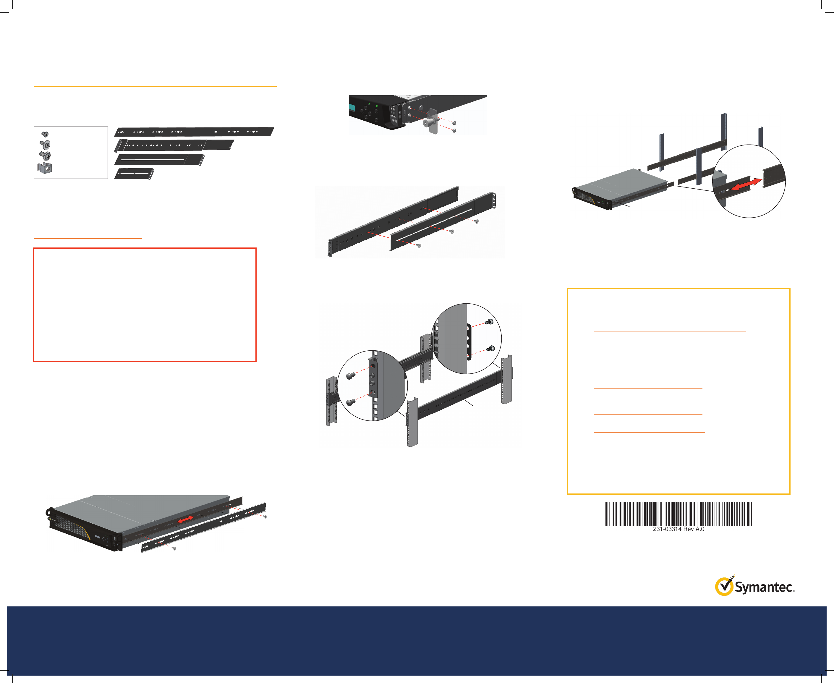
Two/four post slide-rail kit Optional √ √
Rack-mount ears √ √
Safety and Regulatory Compliance Guide
√√√
Quick Start Guide (this document) √√√
Software License Agreement √√√
Hardware Warranty √√√
02 Connect Cables
Symantec recommends plugging in cables, verifying LEDs, and configuring and licensing
the appliance before rack-mounting. If you would rather rack-mount the appliance before
performing configuration tasks, skip to Step 6—Rack-Mount the Appliance.
The following procedure describes a typical in-line deployment for SGS200, SGS400, and
SGS500 appliances (as shown in the above illustration). For information on other deployments,
see the First Steps WebGuide at: http://www.symantec.com/docs/DOC9779
Note: Network cables are not included with the appliance. Make sure to use only straight-through
Ethernet cables. For 1000Base-T operation, Symantec recommends Category 5E cables or better
(Category 6 or 6A) for distances of 330 feet (100 meters).
To deploy the appliance and connect its cables:
a. Disconnect the Ethernet cable (if there is one) between the LAN switch and WAN router.
b. Connect the appliance to the LAN switch with a network cable:
oFor SGS200 and SGS400 appliances, connect the 2:1 port to the LAN switch.
oFor SGS500 appliances, connect the 1:1 port to the LAN switch.
oThe appliance auto-negotiates 10/100/1000 Base-T speed and duplex settings.
c. Connect the appliance to the WAN router with a network cable:
oFor SGS200 and SGS400 appliances, connect the 2:0 port to the WAN router.
oFor SGS500 appliances, connect the 1:0 port to the WAN router.
d. Connect the appliance’s DB9 serial port to a serial terminal or workstation with terminal
emulation software. Use the included null-modem cable. The serial connection is used to
perform the appliance’s initial configuration.
e. For SGS500 appliances, attach the
lug-equipped end of the included
grounding wire (10 AWG) to both
grounding studs on the appliance,
securing it with the star washers
and M5 nuts. Attach the other end
of the grounding wire to a proper
earth-ground.
f. Connect the included AC power cord to the appliance’s power inlet on the rear panel.
Connect the other end of the power cord to a power source. If the appliance has a second
(redundant) power supply, connect it as well.
03 Power on the Appliance and Verify LEDs
To verify the appliance is operational:
a. Confirm the appliance’s power cords are securely connected to a power source.
b. If the appliance does not automatically power on, press the rear soft power switch.
Note: The state of the appliance’s soft power switch (on or off) is retained when power is
removed. This may necessitate pressing the power switch when reapplying power to the
appliance.
c. As the appliance boots, verify the following:
oThe Power LED turns amber.
oNear the end of the boot cycle, the Power LED alternates between amber and green,
indicating an unconfigured state.
oFollowing the initial configuration (see Step4), the Power LED turns green. In addition, the
LCD displays system statistics, which can be scrolled through with the Left/Right Arrows.
The front-panel LEDs indicate the following states::
oPower LED (•) Off: Powered off
(•) Amber: Booting
(•) Amber/green alternating: Unconfigured
(•) Green: Powered on and configured
oSys Status LED (•) Off: No status
(•) Green: Healthy
(•) Amber: Warning
(*) Amber blinking: Critical (or not licensed)
04 Perform the Initial Configuration
You must have the following network information to initialize the appliance:
oAppliance IP address oLink settings (speed and duplex)
oPrimary DNS server IP address oAdmin ID and password
oDefault Gateway IP address oDirector IP address (if using Director)
oSubnet mask
To perform the initial configuration for the appliance:
a. Confirm the appliance’s DB9 serial port is connected to a serial terminal or workstation with
terminal emulation software.
b. Open a terminal emulation program such as Microsoft HyperTerminal®, PuTTY, Tera Term, or
ProComm™.
c. Configure the terminal emulation software to use the following settings:
oBaud rate: 9600 bps oData bits: 1
oParity: none oStops bits: 8
oFlow control: none
d. Power on the appliance (if it is not already powered on) and, when prompted, press Enter
three times.
e. Select how the appliance will be configured:
oManual Setup: Configures the appliance with the Initial Configuration Wizard.
oDirector-Managed Setup: Configures the application with Director. You will need the
Director IP address and registration password for this option. For more information, refer
to the manufacturer’s instructions included with Director.
f. Select how the appliance will be licensed:
oCaching Proxy: The appliance will be deployed with a Mach5 license, which enables the
Sky Management Console, a simplified web interface that provides WAN acceleration and
reporting. This option requires that you specify one of the following deployments:
• Physically in-path
• Virtually in-path with WCCP
oForward Proxy: Filters traffic inside the network, allowing users to browse the Internet
through the proxy.
oReverse Proxy: Directs traffic to web application servers inside the network, while
protecting them from threats.
g. When prompted, enter network configuration parameters. If the appliance is connected to
a network, the Initial Configuration Wizard attempts to verify the DNS server address and
auto-detect link settings.
Warning: Symantec recommends assigning each administrator a unique user ID and password and
storing this information in a secure location. For more information, see the SGOS Administration
Guide available at: https://support.symantec.com/en_US/Documentation.html
Note: Following the initial configuration, the System Status LED blinks amber, indicating the
appliance has not yet been licensed (see Step5).
05 License the Appliance
After the appliance is configured for network access, complete the installation by licensing the
appliance. The ProxySG appliance relies on a base license that includes the primary operating
components of the proxy, and add-on licenses that include optional components, such as
GeoLocation, Web Application Firewall, and WebFilter.
To license the appliance:
a. Open a browser and enter the appliance’s IP address and port number. For example, an IP
address of 192.168.2.42 with a port number of 8082 (the default) translates to the URL:
https://192.168.2.42:8082
b. When prompted, enter the administrator User ID and Password previously specified during
the initial configuration. The Management Console opens.
c. Activate the base license:
oIn the Management Console, navigate to the Maintenance > Licensing > Install tab.
oClick Retrieve. The appliance contacts the Symantec licensing server and the base
license is installed.
d. Activate the add-on licenses, if any were purchased:
oGo to https://support.symantec.com/ and log in with MySymantec credentials.
oChoose Licensing > Network Protection (Blue Coat) Licensing.
oEnter the Activation Code included in your e-fulfilment letter and click Next.
oEnter the appliance’s serial number and click Next.
oFollow the on-screen prompts to complete the activation.
oRepeat these steps to install any additional add-on licenses.
e. Download and install the updated license:
oIn the Management Console, navigate to the Maintenance > Licensing > Install tab.
oClick Retrieve. The appliance contacts the Symantec licensing server and the updated
license is installed.
Quick Start Guide
ProxySG S200, S400, S500
RouterSwitch
Main Site
LAN
ProxySG Appliance
Copyright © 2017 Symantec Corp. All rights reserved. Symantec, the Symantec Logo, the Checkmark Logo, Blue Coat, and the Blue Coat logo are trademarks or registered trademarks of Symantec Corp. or its affiliates in the U.S. and other countries. Other names may be trademarks of their respective owners. This document is provided for informational purposes only and is not intended as advertising. All warranties relating to the information in this
document, either express or implied, are disclaimed to the maximum extent allowed by law. The information in this document is subject to change without notice. Part Number: 231-03314 Rev A.0
THE DOCUMENTATION IS PROVIDED “AS IS” AND ALL EXPRESS OR IMPLIED CONDITIONS, REPRESENTATIONS AND WARRANTIES, INCLUDING ANY IMPLIED WARRANTY OF MERCHANTABILITY, FITNESS FOR A PARTICULAR PURPOSE OR NON-INFRINGEMENT, ARE DISCLAIMED, EXCEPT TO THE EXTENT THAT SUCH DISCLAIMERS ARE HELD TO BE LEGALLY INVALID. SYMANTEC CORPORATION SHALL NOT BE LIABLE FOR INCIDENTAL OR
CONSEQUENTIAL DAMAGES IN CONNECTION WITH THE FURNISHING, PERFORMANCE, OR USE OF THIS DOCUMENTATION. THE INFORMATION CONTAINED IN THIS DOCUMENTATION IS SUBJECT TO CHANGE WITHOUT NOTICE. SYMANTEC CORPORATION PRODUCTS, TECHNICAL SERVICES, AND ANY OTHER TECHNICAL DATA REFERENCED IN THIS DOCUMENT ARE SUBJECT TO U.S. EXPORT CONTROL AND SANCTIONS LAWS, REGULATIONS AND
REQUIREMENTS, AND MAY BE SUBJECT TO EXPORT OR IMPORT REGULATIONS IN OTHER COUNTRIES. YOU AGREE TO COMPLY STRICTLY WITH THESE LAWS, REGULATIONS AND REQUIREMENTS, AND ACKNOWLEDGE THAT YOU HAVE THE RESPONSIBILITY TO OBTAIN ANY LICENSES, PERMITS OR OTHER APPROVALS THAT MAY BE REQUIRED IN ORDER TO EXPORT, RE-EXPORT, TRANSFER IN COUNTRY OR IMPORT AFTER DELIVERY TO YOU.
Page 2
SG S200, SG S400, SG S500 Quick Start Guide
06 Rack-Mount the Appliance
The slide-rail mounting kit included with the SGS400 and SGS500 appliances (available as an
option for SGS200 appliances) allows the appliance to be rack-mounted in a two- or -four-post
equipment rack. The slide-rail kit includes the following parts:
Note: To rack-mount the appliance, you may need an M4 nut driver or adjustable wrench,
#2Phillips head screwdriver, and rack screws.
Note: The following procedure documents how to install the appliance in a four-post equipment
rack. For comprehensive information on rack-mounting the appliance, including other
configurations, see the S-Series Maintenance and Upgrade Guide at:
http://www.symantec.com/docs/DOC9795
To install the appliance in a four-post equipment rack:
a. Disassemble the two slide-rail assemblies:
oFully extend each slide-rail by sliding out the inner rails until they reach the stop.
oRelease the white slide latches (toward the rear of the inner rails) and slide the inner rails
all the way out.
oSlide-rails are symmetrical and can be used with either side of the chassis.
b. Attach the two inner rails to the appliance:
oAlign each inner rail to the mounting posts on each side of the chassis. Slide the rail
toward either the front (SGS200 and SGS400) or rear (SGS500) of the chassis until
each of the mounting posts snap into place.
oSecure the inner rails to the appliance with M3 screws:
• For SGS200 and SGS400 appliances, use one M3 screw in the center of each rail.
• For SGS500 appliances, use two M3 screws in each rail.
c. For SGS200 and SGS400 appliances, install the two rack ears. Align them with the mounting
posts on the chassis sides near the front of the appliance and secure them with the included
fasteners.
d. Assemble the two slide-rails and install them in the rack:
oLoosely attach Rail_C to Rail_A. Secure the rails with three M3 screws inserted through
the slot in Rail_C and screwed into three holes in Rail_A. Make sure the screws are
equidistant from each other so the load will be evenly distributed on the rail. Do not yet
fully tighten the screws.
Note: The precise attachment location of the screws will depend on how far Rail_C will
extend or retract to fit the rack. It may be necessary to remove Rail_C from Rail_A to
determine the proper installation length.
oInstall the assembled slide-rails in the rack:
• Secure the front bracket for Rail_A to the outside front of the rack using two rack
screws. Do not yet fully tighten the screws. You will do so after the appliance is
installed in the rack.
• Extend or retract Rail_C to align the rear bracket with the outside rear of the rack.
Secure the bracket with two M3 screws. Do not yet fully tighten the screws. You will
do so after the appliance is installed in the rack.
• Tighten the side-mounting screws for Rail_C.
• Verify the slide-rail assemblies are installed at the same rack eight.
e. Install the appliance in the rack:
oAlign the inner rails attached to the appliance with the slide-rails in the rack and slide the
appliance half-way into the track.
oPress the gray locking tabs on the inner rails to slide the appliance all the way into the rack.
oSlide the appliance out of the rack, far enough to access the rack screws. Fully tighten
the rack screws for the front and rear brackets to secure the slide-rails to the rack.
oGently push the appliance all the way to the back of the rack and tighten the
thumbscrews on the retaining ears to prevent the appliance from sliding out.
f. Reconnect the cables as documented in Step 2—Connect Cables and verify the appliance is
functioning as in Step 3—Power On the Appliance and Verify LEDs.
Technical Support
oContact Information
https://support.symantec.com/en_US/contact-support.html
oMySymantec
https://www.mysymantec.com
Documentation
ProxySG First Steps WebGuide
ohttp://www.symantec.com/docs/DOC9779
Appliance Documentation
oS-Series Maintenance and Upgrade Guide
http://www.symantec.com/docs/DOC9795
oS200 Series Safety and Regulatory Compliance Guide
http://www.symantec.com/docs/DOC10311
oS400 Series Safety and Regulatory Compliance Guide
http://www.symantec.com/docs/DOC9996
oS500 Series Safety and Regulatory Compliance Guide
http://www.symantec.com/docs/DOC10248
CAUTION:
Before rack-mounting the appliance:
oPower off the appliance and disconnect all cables.
oVerify that the weight of the system does not exceed the rack’s
fully populated weight limit. For more information, refer to the
manufacturer’s instructions included with the rack.
oFor weight stability, load the rack from thebottomup.
oRead the “Rack Mount Warnings” section of the Safety and
Regulatory Compliance Guide.
oTake adequate safety and grounding measures to avoid creating an
electrical shock hazard and to prevent bodily injury.
Rail_C
Rail_A
Inner Rail (2)
Rail_A (2)
Rail_C (2)
Rail_B (4) (used only for 2-post racks)
M4x4L screws (4)
M4x5L screws/washers (4)
M6 rack screws/washers (8)
M6 cage nuts (8)
Rail_C
Locking tab

Other manuals for S500

1

This manual suits for next models

2

Other Symantec Gateway manuals

Symantec 5000 Series User manual

Symantec

Symantec 5000 Series User manual

Symantec 360R - Security Gateway SGS User manual

Symantec

Symantec 360R - Security Gateway SGS User manual

Symantec 460R - Gateway Security Service manual

Symantec

Symantec 460R - Gateway Security Service manual

Symantec Security 5600 Series, Security 5400 Series,Clientless VPN 4400... Instruction Manual

Symantec

Symantec Security 5600 Series, Security 5400 Series,Clientless VPN 4400... Instruction Manual

Symantec S450 Series User manual

Symantec

Symantec S450 Series User manual

Symantec 320 Technical manual

Symantec

Symantec 320 Technical manual

Symantec 4420 User manual

Symantec

Symantec 4420 User manual

Symantec 360R - Security Gateway SGS Instruction Manual

Symantec

Symantec 360R - Security Gateway SGS Instruction Manual

Symantec 300 Series User manual

Symantec

Symantec 300 Series User manual

Symantec SGM 1600 User manual

Symantec

Symantec SGM 1600 User manual

Symantec SSP-S410 User manual

Symantec

Symantec SSP-S410 User manual

Symantec 4400 Series User manual

Symantec

Symantec 4400 Series User manual

Popular Gateway manuals by other brands

frako EMG 1500-PN operating manual

frako

frako EMG 1500-PN operating manual

Raisecom RC953-GESTM1 Command manual

Raisecom

Raisecom RC953-GESTM1 Command manual

Advantech WISE6610N user manual

Advantech

Advantech WISE6610N user manual

Dialogic IMG 1010 quick start guide

Dialogic

Dialogic IMG 1010 quick start guide

AudioCodes Mediant 500L MSBR Hardware installation manual

AudioCodes

AudioCodes Mediant 500L MSBR Hardware installation manual

ZyXEL Communications P-873HNU-51B user guide

ZyXEL Communications

ZyXEL Communications P-873HNU-51B user guide

Advantech EKI-1221IEIMB user manual

Advantech

Advantech EKI-1221IEIMB user manual

Verizon CR200A user manual

Verizon

Verizon CR200A user manual

QNAP TS-109 user manual

QNAP

QNAP TS-109 user manual

Bosch Conettix D6600 installation guide

Bosch

Bosch Conettix D6600 installation guide

H3C VG Series Configuration manual

H3C

H3C VG Series Configuration manual

AMX NXR-ZRP quick start guide

AMX

AMX NXR-ZRP quick start guide

Planet WPG-120 user manual

Planet

Planet WPG-120 user manual

NETGEAR C6300BD user manual

NETGEAR

NETGEAR C6300BD user manual

Maretron IPG100 user manual

Maretron

Maretron IPG100 user manual

Emerson Smart Wireless Gateway 1420 Technical note

Emerson

Emerson Smart Wireless Gateway 1420 Technical note

Pace 5111NV installation guide

Pace

Pace 5111NV installation guide

Funkwerk bintec R230aw user guide

Funkwerk

Funkwerk bintec R230aw user guide

manuals.online logo
manuals.online logoBrands
  • About & Mission
  • Contact us
  • Privacy Policy
  • Terms and Conditions

Copyright 2025 Manuals.Online. All Rights Reserved.