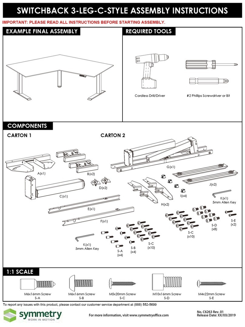
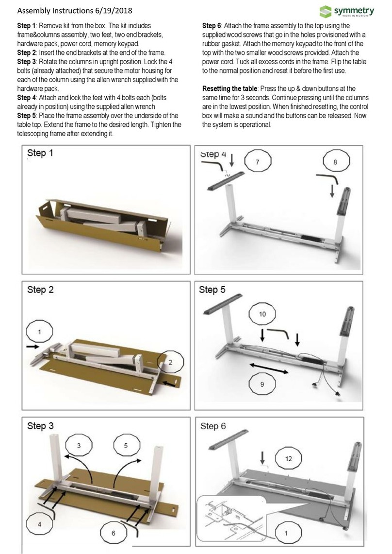
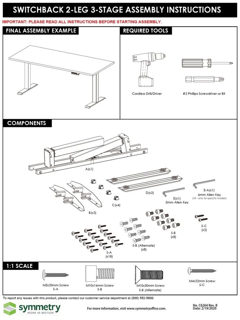
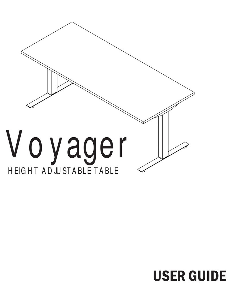
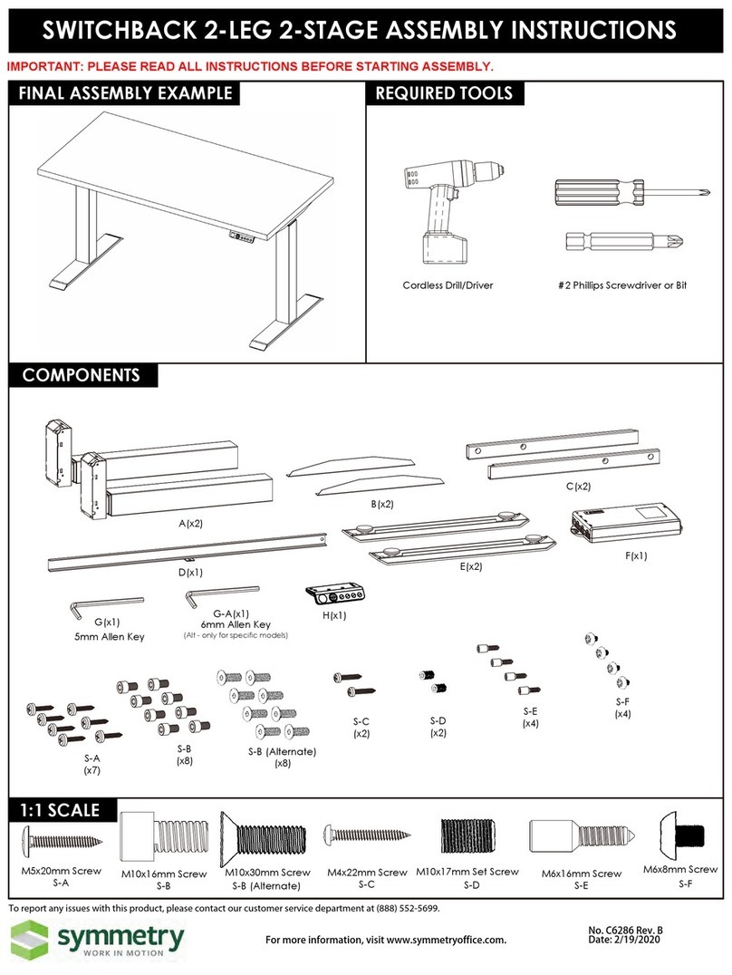
Symmetry ENDEAVOUR User manual

!
1!
•
!
!
!
!!!!!!!!!!!!!!!!!!!!!!!!!!!!!!!!!!!!!!!!!!!!!!!!!!!!!!!!!!!ENDEAVOUR
HEIGHT ADJUSTABLE DESK
MANUAL FOR ASSEMBLY AND USE
!
UL Number: E485560
!
IMPORTANT:
Any user or installer of desk base must study this manual carefully.
If this desk is sold, please provide the manual to the buyer.
Questions? Please contact Symmetry @ 888-552-5699 or email info@symmetryoffice.com
!

!
2!
TABLE OF CONTENTS PAGE
1.
SAFETYANDWARNINGS 2
2.
USAGE
2
3.
SETUPANDINSTALLATION 2
4.
PARTS LIST 3
5.
ASSEMBLY INSTRUCTIONS 4 to 10
6.
TECHNICAL SPECIFICATIONS 11
7.
TROUBLESHOOTING GUIDE 11
1.
SAFETY AND WARNINGS
2.
USAGE
This height adjustable desk has an electric motor and is designed for use in dry work areas only.
The desk height is adjustable so that it can be positioned at the most ergonomically suitable height. These
desks are designed only for the purposes included in this manual. They should not be used
in environments with high humidity or dampness. Any other use is at user’s risk.
Do not move around, crawl or lie under the desk frame. Do not sit or stand on the desk frame.
Childrenshould neveruse the deskunlessthey aresupervised byadults.
Liability: Under no circumstances does the manufacturer accept warranty claims or liability claims
for damages caused from improper use or handling of the desk frame other than that which
is described in this operation manual.
3.
SETUP AND INSTALLATION
Once the desk has been assembled, adjust the feet so that the desk is level and does not shift its position.
After this, connect the desk to the 110v or 230v outlet and the desk is ready for use.
Check that no cables can get jammed.
Choose a placement for the desk that’s a safe distance from window frames, radiators, furniture etc. so
that people do not get stuck or trapped by the desk.
Do not place any objects that are taller than 20” underneath the desk.
After it has been assembled, when moving the desk, DO NOT lift the desk by the desktop. Lifting
tis way can stress the fasteners connecting the desk base to the desktop. Lower the desk completely and
lift the desk by grabbing the top of the desk base or by removing the desktop first.

!
3!
4.
PARTS LIST
Components
!"#$
!!!!
!!!!!!!!!!!!!!!!!!!!!!!!!!!!!!!!!!!!!!!!!!!!!!!!!!!!!!!!!!!!!!!
Qty 1 Pre-assembled legs +frame Qty 2 Feet Qty2 Side Brackets Qty 1 Keypad
%&'
Qty 1 power cord Qty 1 Control box Qty 4 Leveling Studs
Please count all pieces before disposing of any carton or packing material.Use a padded or carpeted
areafor
Hardware
8 9 10 11 12 13 14 15
!
4mm 1PC 5mm 1PC M6*16 8PCS M6*458PCS M8*16 8PCS M5*20 6PCS M5*16 2PCS 8PCS

!
4!
assemblyto avoiddamage.For easeand safety,we recommend two peopleforassembly
ASSEMBLY INSTRUCTIONS
A.
First, Lay out all components and hardware to ensure that you have all the parts listed on the compo-
nents list.
!!
!
!
!
!
1!
4!
6!
3!
2!
5!
3!
1!
2!
10. 8!PCS!!M6*16!Screws!
!
11. 8!PCS!!M6*45!Screws!
!
12. 8!PCS!!M8
*16!!Nuts(!Pre-assembled!in!the!frame!)!
!
13. 6!PCS!!M5*20!Pan!Head!Screws!
!
14. 2!PCS!!M5*15!Pan!Head!Screws!
!
15. 10!PCS!!Cable!Clips!
!
!
1. Qty!1!!Pre-assembled!legs!and!frame!
!
2. Qty!2!!Feet!
!
3. Qty!2!Side!Brackets!
!
4. Qty!1!Keypad!
!
5. Qty!1!Power!Cord!
!
6. Qty!1!Control!Box!
!
7. Qty!4!Leveling!Stud!
!
8. 1!PC!!4mm!!Allen!Key!
!
9. 1!PC!!5mm!!Allen!Key!
!

!
5!
B.
Take out the pre assembled lifting column and frame, tighten the screws (Part
#
10)
!
!
!
!!!!!!!!!!!!!!!!!!!!!
!
!
!
!
!!!!!!!!!!!!!!!!!!!!!!!!!!!!!!!!!!!!!!!!!!!!!!!!!!!!!!
!!!!!!!!!!!!!!!!!!!
!
!
10!
10!
10!
10!
10!
10!
10!
10!

!
6!
C.
Take out Feet (Part #2), Use screw (Part #11), to fit the Feet on the lifting
column bottom, and fit Leveling Stud (Part #7), on the feet.
!
!!!!!!!!!!!!!!!!!!!!!!!!!!!!!!!!!!! !
!!!!
!
D.
Turn around the desk to upright down.
!
!!!!!! !!!!!!!!!!!!!!!!!!!!!!!!!! !
!
!
!
!
E.
Tighten the side brackets on the desk frame, one for left side, one for right side.
!
!!!!!!!!! !!!!!!!!!!!!!!!!!!!!!!!!!!!!!!!!!!!! !
!
!
!
!
10!

!
7!
F.
Use a tape to measure the width, and adjust the cross rail in the middle of the frame. set up
the width you want, Fit the control box into the desk frame. Then tighten the screws
!
!!!!
!!!!!!!!!!!!!!!!!!!!!!!!!!!!!!!!!!!!!!!!! !
!
!
!
!
G.
Your desktop may or may not be pre-drilled. Please check both sides of the desktop before
placing the desk base on it for pre-drilling! Carefully place the upside down desk base on the
underside of the desktop.
Note: minimum top size: 47.2” wide x 23” deep
Adjust the width of the base to fit the desktop by
sliding
the
two
halves
outward
(43.3”
to 78. 7
”
max).
Place the base where you want it.Some will want the frame to be
all
the
way
to
the
edge
of
the
desk.
We
recommend leaving
at
least
1/2”
ofdesktopwidth(oneachside), protruding beyond the frame
width.
Depth: The minimum depth top you can use is 23”. We recommend that you center the base on the
desktop (front to back). If your top is 25.5”-27.5” and you want the rear edge of the top in line with
the rear edges of the feet, offset the top toward the back.
Center the frame by using the desktop edge
asa reference. Measureto themetalbrace.
Do not use the screw holes as a point ofreference.

!
8!
!
I. Double-check that the base is centered on the underside of the desktop and is located where you
want it. Also, double-check that the included wood screws are not too long for your desktop and won’t
puncture the surface when screwed all the way in.
We recommend you pre-drill any holes
neededfor fasteners connecting
Never use countersunk screws
to
fasten into the desktop.
the base to the top.
NOTE: PLEASE ENSURE THAT YOUR
DESKTOP DOES NOT ALREADYHAVE
HOLES BY CHECKING BOTH SIDES.
This will make it easier to attach the screws
and willgreatly lessen the stress caused by
driving a screw into the desktop material.
This will cause much greater stress
onthedesktop.Ensureanyscrewused
will not puncture through the desktop surface
orotherwise damage the material.
Now, proceed with securing the desk base to the desktop using qty 6 of the larger Pan Head
Screws.(Part#13)
Install as follows:
3 per side bracket (left)
3 per side bracket (Right)
J.
IN THIS FOLLOWING STEP, DO NOT OVERTIGHTEN SCREWS. OVER TIGHTENING MAY
CAUSE THE PLASTIC ON THE COMPONENTS TO BREAK.
We recommend you pre-drill any holes
needed for fasteners connecting the
Neverusecountersunkscrewstofasten
into the desktop. This willcause much
Control box to the top. This will make
it easier to attach the screws and will greatly
lessen the stress caused by driving a screw
into the desktop material.
greater stress on the desktop. Ensure
any screw used will not puncture through
the desktop surface or otherwise damage
thematerial.
Use
qty
2
of
the
smaller
Pan
Head
Screws(Part#14)

!
9!
to attach the Control Box (Part #6). Ensure enough
clearance at the wire ports for cable connections.
K.
IN THIS FOLLOWING STEP, DO NOT OVERTIGHTEN SCREWS. OVER TIGHTENING MAY
CAUSE THE PLASTIC ON THE COMPONENTS TO BREAK.
Place the Keypad (Part #4) so the front of the keypad runs flush
with
the
desktop
edge
(or
recessed
up
to
1/8”).
The
Keypad
can
be placed anywhere along the front edge of the desk, but we
recommend placing it near the side so it doesn’t interfere with
your chair or legs when seated.
Use
qty
2
of
the
smaller
Pan
Head
Screws (Part#14)
to
attach
the Keypad (Part #4) to the desktop.
!!!!!!!!!!! !

!
10!
L.
Connect
the
Wires
as
per
the
diagram
below.
Use
the
adhesive-backed
Cable
Clips
(Part
#18)
to
secure the Connecting Wires, so they don’t sag.
M.
Turn the assembled desk right-side-up. With two people, grab the desk by the base (not the desk-
top) and turn the desk right-side up. Adjust the Leveling Studs on the Feet (Part #2) as needed.
N.
Plug the Power Cord into a 110v electric outlet.
*** IMPORTANT! ***
YOU MUST RESET THE DESK PRIOR TO USE:
For the first time use it,
press and hold the “DOWN”
button on the Keypad
untilthe desk reaches its
lowest height and bounce back and shows the
lowest position height, then release the Keypad,
reset done.
Your desk is now ready to use.
To program up to four presets:
Use the up/down buttons to find a desired height, then press “M” followed by a
number
1
–4.
To switch display height from cm to inch, or inch to cm :
Press hold “M” and “UP” buttons for 15 seconds, the height display will switch to another metric.

!
11!
TECHNICAL SPECIFICATIONS
5.
TROUBLESHOOTING
--Reset!Instructions—
If experiencing error messages showing on the keypad or no response when trying to raise or lower:
•
Unplug the power cord and hold the down key for 20 seconds.
•
Plug the power cord back in.
•
Press M and hold the DOWN button on the Keypad until the desk reaches its lowest height.
And hold the DOWN button again until it bounces back and shows the lowest position
height in the Keypad. Release Down button, reset done.
Yourdesk is now ready to use.
•
After keypad display the current height, and you should be able to operate it now.
•
You may need to do this if the desktop is ever unplugged or loses power.
If
the
handset
displays
error
messages
“E01”
“E02”or
“E03”,
confirm
that
all
wired
connections
are
secure
(legs
to cables, cables to control box). Then perform the reset procedure above. If the error message
persists
after the reset procedure of if the height between the legs exceeds 1.5 inches stop the reset
procedure and
contact your retailer or manufacturer.
If the handset displays “E04””,E05”or “E06”, check if any of the leg is over loaded, and remove the
weight, operate again.
If the handset displays “ER0”, let the base cool down for 20 minutes.
If thedeskseemstobeuneven,trytheresetinstructionsabove.If that does not work youmay
need
to adjustthe levelers atthe bottom ofthe foot.
In the event of a power outage or if the power cord is unplugged,
amanualresetmaybenecessary(seeResetInstructionsabove)
This product is designed with a duty cycle of 10%
(2 min. on, 18 min. off)
Keep Children away from electric height-adjustable desks, control
units and handsets. There is a risk of injury and electric shock
Do not open any of the components: lifting columns, control box, or
handset.There is a danger of electric shock
Keep all electrical components away from liquids
Height Range
23.4”– 48.6”(withoutdesktop)
Adjustable frame
43,3”
m
i
n
– 78.7
”
m
a
x
Travel Speed
1.5” per
s
e
c
o
n
d
Weight Capacity
225 lbs.
Duty Cycle
10%, Max. 2 mins on, 18 mins off
Function
Sit- Stand Desk with 4 Memory position in the handset
Anti-collision technology to prevent damage
i
i
Table of contents
Other Symmetry Indoor Furnishing manuals
Popular Indoor Furnishing manuals by other brands

Next
Next 944991 Assembly instructions

Blanco
Blanco BLANCOSUPREME 511-967 Specification sheet

Courtyard Creations
Courtyard Creations KUS897C-WM Assembly instructions

Riverside Furniture
Riverside Furniture Joelle 63054 Assembly instructions

Geuther
Geuther Marit 1142WK manual

Poliman
Poliman ANNE C0805 Assembly lnstructions