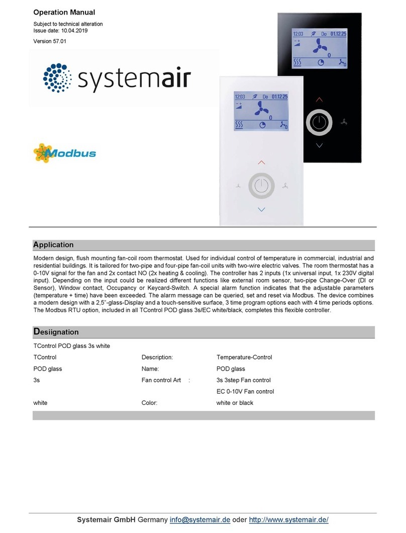
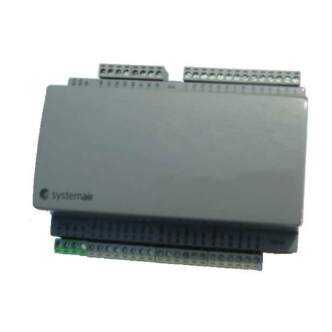
System air EC Vent User manual

EC Vent
User Manual
-EN_GB
15-03-2011V.A-003

Contents
1 Warnings................................................................................................................................... 1
2 Product Description.................................................................................................................... 1
2.1 Room unit ........................................................................................................................ 1
2.1.1 Display Symbols ..................................................................................................... 3
3 Operation .................................................................................................................................. 4
3.1 Before starting.................................................................................................................. 4
3.2 Program overview ............................................................................................................ 4
3.2.1 Navigation .............................................................................................................. 4
3.2.2 User menu.............................................................................................................. 4
3.2.3 User Overview ........................................................................................................ 6
3.2.4 User Menu Auto Mode ............................................................................................ 8
3.2.5 Service Menu .........................................................................................................10
3.2.6 Installation .............................................................................................................12
3.2.7 User Interface.........................................................................................................16
3.2.8 Alarm Menu............................................................................................................18
3.2.9 Temperature Control ...............................................................................................19
3.2.10 CO2Control ..........................................................................................................21
3.2.11 Humidity Control....................................................................................................23
3.2.12 Manual Control .....................................................................................................24
3.2.13 Time Control .........................................................................................................26
3.2.14 Pressure Control ...................................................................................................27
3.2.15 DI Control .............................................................................................................29
3.2.16 Flow Control .........................................................................................................31
3.2.17 Slave Control........................................................................................................33
3.2.18 Heater/Cooler Control............................................................................................34
3.2.19 Output ..................................................................................................................37
3.2.20 Alarm Setting ........................................................................................................38
3.3 Set up cases ....................................................................................................................39
3.3.1 Pressure control with outdoor temperature compensation..........................................39
3.3.2 Constant air volume with CO2controlled forced ventilation.........................................42
3.3.3 Manual fixed min. airflow with humidity controlled forced ventilation ...........................45
3.3.4 Fixed rpm with presence detector control..................................................................46
3.3.5 Free cooling with control of room radiator .................................................................47
3.4 Set up of operation schedules ...........................................................................................49
3.4.1 Set up example.......................................................................................................51
1Warnings
The following admonitions will be presented in the different sections of the document.
Danger
• Make sure that the Mains supply to the unit is disconnected before performing any maintenance or
electrical work!
• All electrical connections must be carried out by an authorized installer and in accordance with
local rules and regulations.
2 Product Description
2.1 Room unit
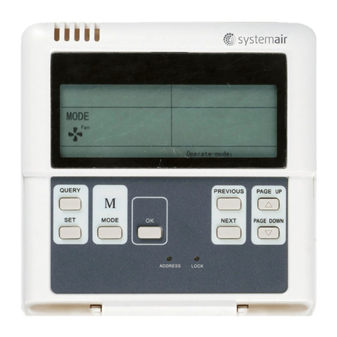
The objective of the room unit is to display the information provided by the installed sensors and make
it possible for the user to enter desired settings. The room unit is equipped with 2 internal sensors;
Temperature and humidity sensor, which register the temperature and humidity in the location of the
installed room unit. It is possible to connect 2 extra sensors to the internal connection block.
Up to 10 room units can be active simultaneously.
Note:
The installed room units can only be regulated one by one. It is not possible to perform settings on
two or more controls simultaneously!
In order for the room unit to function the control board needs to be installed and connected. See
“Installation Instructions” for more information.
EC Vent User Manual
1Systemair AB

Fig. 1 Room unit components
Position Description Explanation
1Display Shows symbols, menus and settings
2Selection knob Move through the menu lists or change
settings and values by turning the knob
left or right
3Confirm button Confirm menu choices or settings by
pressing the button
4 Back button Step back in the menu levels by
pressing the button
EC Vent User Manual
2Systemair AB

2.1.1 Display Symbols
Symbol Description Explanation
Fan speed Illustrates the current set fan speed. The
speed setting is stepless or in steps determined
by the user. The speed is also displayed as
percentage of the maximum fan speed at the
bottom of the display (valid if manual mode is
selected)
Empty symbol equals stopped fan and
completely filled symbol equals maximum
speed (100%)
The fan speed can be set manually by turning
the selection knob while in manual mode.
Temp set Illustrates the current set temperature.
Temperature icon is connected to the set
point for the heater/cooler. If no heater/cooler
controller is activated the icon indicates the
setting of the first temperature controller for
the fan. If there are no temperature controllers
in the system the temperature icon is not
shown. The temperature is set in steps of 0,5°C
and can be changed manually by turning the
selection knob.
Service Access to the service/setup menu by pressing
the confirmation button
Login to “Service” with “1111” and to “Setup”
with “2222”.
Alarm Shows only if an alarm is active and not
blocked. Icon is flashing when an alarm is
active
Check box Used to marked selectable and selected items
(unmarked and marked boxes).
EC Vent User Manual
3Systemair AB

3Operation
3.1 Before starting
Before starting up the system make sure you have checked the following:
• That the equipment is installed according to the installation instructions
• That the correct accessories are used for the intended function
• That you have read and understood this manual.
3.2 Program overview
The program interface is separated in three levels.
• User level is intended to be used by any user of the system. It’s only possible to change a limited
number of parameters
• Service level is intended to be used by persons with some knowledge of the system. For example care
taker or similar
• Installation level is used for advanced setting and is intended for the installation personnel that do the
initial setup of the complete system.
3.2.1 Navigation
The room unit has two buttons and a knob.
• Menu selector (choose function and move in menus)
•Confirm(buttontoconfirm choice)
• Back (button to go back in menu level)
Items in the menu that lead to a sub menu level are marked with >>. Itemsthatleadtoamenuwith
changeable items are marked with>. Changeable Parameters and values in menus are marked with
underscore. When turning the knob the selected value is marked with inverted background colour. The
Confirm button will enable changes of value, this is indicated by flashing the inverted background colour
on and off.
After a value has been changed the change must be confirmed with the Confirm button. If the back button
is used the value will go back to previous. Inactivity for 1 min. is the same as selecting back button.
The display back light will be activated from any user input. The back light goes off after 1 min. of inactivity
except for the adjusting menu where the back light is always on
The password menu has a time out of 15 sec.
3.2.2 User menu
The control mode list shows activated selection. If only manual is chosen and a manual controller is
selected the controller mode menu is not shown
Manual controller setting menu has no time out.
The temperature icon is connected to the set point for the heater/cooler. If no heater/cooler controller is
activated the icon is connected to the first temperature controller for the fan. If there are no temperature
controllers in the system the temperature icon is not shown. The Alarm icon flashes in case of alarm and
an alarm message is shown; if more than one alarm is activated the messages alternate.
In the bottom of the display the actual operate mode is shown.
This can be:
•Auto
• Boost: 00:30 (remaining time counter, in this example the remaining boost time is 30 minutes)
EC Vent User Manual
4Systemair AB

• Extended time: 00:30 (remaining time counter, in this example the remaining extended time is 30
minutes)
•Away
• Manual: (If the controller is set to stepless the fan signal output is shown in %. If step controller is
selected the selected step is shown.) The manual speed is shown if a manual controller is activated and
the system is in auto mode.
3.2.2.1 Sleep Mode
If the sleep mode is activated the system will go to sleep mode 5 min. after last user interaction, except
when the adjusting menu is selected. When the system is in sleep mode any user input will change the
system to user menu. If a user password is selected a password question will appear.
3.2.2.2 Operation mode
Boost: When entering the Boost functionadefaulttimeisshownandatimefield is selected for edit.
(Boost speed is equal to 100% fan speed)
Default time is set in User interface menu
1. Select a time with the selection knob, confirmthetimeandthetimerstarts
2. Return to main menu with the back button or time out
3. Text Boost and remaining time is shown under the display icons
Extended time: Disables the effect of the schedule. If no schedule is programmed the function is
hidden. Same function and procedure as Boost function.
Away: Activates the away speed. Is Aborted by selection of boost, extended time or auto mode. Away
speed is set in User interface menu.
Auto: Return to Auto mode.
Manual:Activatefixed speed with manual setting. Can be step or stepless. The menu for changing speed
has no time out. The fan speed can be higher than the set manual speed if a separate room unit (up to 10
pcs of RU can be installed) gives a higher signal to the fan.
EC Vent User Manual
5Systemair AB

3.2.3 User Overview
Auto
Monday
12:00
Auto
Password
Service
Setup
xxxx
Password
xxxx
12:00
20°C
Auto
Fan Speed <500RPM
AB
C
D
E
F
G
Fig. 2 User overview
EC Vent User Manual
6Systemair AB

Table 1: Explanations User overview
Position Description (figure 2)
AShows a warning symbol with the text Fan speed
<500 rpm. Indicates that no fan speed setting has
been made
BSleep mode display option.
Will be shown after 5 min. of inactivity if the
function is activated.
CUser password
Displayed after pressing the confirmation button
when standing in sleep mode (section 3.2.6.1)
DSymbol has different meaning:
If manual mode is activated (section 3.2.12) the
symbol will change according to the actual fan
speed
If Away, Auto or Boost mode is chosen the symbol
will be filled accordingly (little, medium, full).
For more info. (section 2.1.1 and section 3.2.4).
ESymbol has different meaning:
If no temperature control or heater/cooler is used
then the symbol will not be visible
If a heater/cooler is installed the desired working
point of the heater/cooler can be changed here.
If the fan is controlled with the help of a temperature
sensor you can change the desired temperature
between the Max/Min set point here. If a fixed set
point has been chosen the symbol is visible but no
changes can be done (section 2.1.1 and section
3.2.9).
F Push to enter either the installation mode or the
service mode
G Write the password for the mode you want to enter
EC Vent User Manual
7Systemair AB

3.2.4 User Menu Auto Mode
Auto
Fan Speed <500 RPM
Setting
Password
Service
xxxx
Away
Auto
Extended time
Boost
Manual
Away
Auto
Extended time
Boost
Manual
Away
Auto
Extended time
Boost
Manual
Boost
Duration 00:30
Extended time.
Duration 00:30
Away
Auto
Extended time
Boost
Manual
Away
Auto
Extended time
Boost
Manual
Fan speed 33%
or
Fan step 1
Set temp /Fixed temp set
A
B
C
D
E
F
G
H
I
Fig. 3 Auto Mode
EC Vent User Manual
8Systemair AB

Table 2: Explanations User menu Auto mode
Position Menu Headline Description (figure 3)
AAway Activate the Away function. For more info.
(section 3.2.2.2 and section 3.2.7).
BAuto
Abort away, boost or extended time.
The fan will then be controlled by the
installed sensors and/or week schedule.
For more info. (section 3.2.2.2 and section
3.2.6.1).
CSet temp/Fixed temp set Change set point of heater/cooler controller
or temperature controlled fan.
DSetting Push to enter either the installation mode
or the service mode
EAlarm
Alarm
Symbol appears if there is an active alarm
(section 3.2.8).
FExtended time
Activate the Extended time function.
For more info. (section 3.2.2.2 and section
3.2.7).
GBoost Activate the Boost function. For more info.
(section 3.2.2.2 and section 3.2.7)
HManual
If manual mode is chosen the fan can be
controlled in a stepless mode if this mode
is chosen (section 3.2.12).
IFan step 1
If manual mode is chosen the fan can be
controlled in a step mode if this mode is
chosen (section 3.2.12).
EC Vent User Manual
9Systemair AB

3.2.5 Service Menu
Service
•Fan set point adjustment
•Heater / Cooler set point
•Time and Date
Fan set point
xxx °C / ppm / %Rh / Pa / l/s
Service
•Fan set point adjustment
•Heater/Cooler set point
•Time and Date
Time and date
HH:MM
DDD
Service
•Fan set point adjustment
•Heater/Cooler set point
•Time and Date
Heater/Cooler set point
xxx °C
Fan set point
Controller
•1 Controller name
•2 Controller name
•3 Controller name
•4 Controller name
•5 Controller name
.
.
.
ABC
D
E
Service
•Fan set point adjustment
•Heater/Cooler set point
•Time and Date
•SW Version
SW Ver CB RU
Main X.X.X X.X.X
Boot X.X.X X.X.X
String X.X.X
•SW Version
•SW Version
•SW Version
F
Fig. 4 Service Menu
Table 3: Explanations
Position Menu Headline Description (figure 4)
AFan set point adjustment Service menu gives you the possibility to
change some basic features.
BController name
Chose for which controller function you
want to change the set point for. The
different controller functions has to be set
in the installation menu before the appear
here (section 3.2.6).
CFan set point
Change the fan set point so that the fan
always works towards achieving the preset
set point. The set point has to be within
the pre-defined range, see section that
corresponds to the desired control mode.
DHeater/Cooler set point
Choose the desired set point for the
heater/cooler. If no heater/cooler has been
installed this option will not be shown
(section 3.2.18).
EC Vent User Manual
10 Systemair AB

Explanations cont'd
Position Menu Headline Description (figure 4)
ETime and Date Change the time and date
FSW Version Software version
EC Vent User Manual
11 Systemair AB

3.2.6 Installation
3.2.6.1 Installation-1
Control mode
•Disable
•Temperature Control
•CO2Control
•Humidity Control
•Pressure Control
•Flow Control
•Slave Control
Installation
•Controllers
•User interface
•Security
•Output
•Alarm Setting
•Address
•Adjusting
•Units
Security
•User level
•Service Level
•Installation level
Security
•User level
•Service level
•Installation level
Security
•User level
•Service Level
•Installation level
User level
Change Password
Actual XXXX
New XXXX
Service Level
Change Password
Actual XXXX
New XXXX
Installation level
Change Password
Actual XXXX
New XXXX
Installation
•Controllers
•User interface
•Security
•Output
•Alarm Setting
•Address
•Adjusting
•Units
Installation
•Controllers
•User interface
•Security
•Output
•Alarm Setting
•Address
•Adjusting
•Units
Controllers
•Control 1
•Control 2
•Control 3
•Control 4
•Control 5
•Manual Control
•Heater / Cooler C ontrol
•Time Control
•DI Control
Controllers
•Control 1
•Control 2
•Control 3
•Control 4
•Control 5
•Manual Control
•Heater/Cooler Control
•Time Control
•DI Control
.
•Calibration
•Calibration
•Calibration
ABC
D
E
FG
H
I
J
Fig. 5 Installation-1
EC Vent User Manual
12 Systemair AB

Table 4: Explanations installation-1
Position Menu Headline Description (figure 5)
AInstallation Installation, main menu options
BControllers
Control 1-5 gives you the possibility to run
thefanwiththehelpof5differentsensors,
either simultaneously or individually. The
fan will be controlled by the sensor that
gives the fan the highest output.
CControl mode
Choose what kind of control mode for the
fan that will be used.
Slave control allows the fan speed to be
controlled from a main control system
(section 3.2.9, section 3.2.10, section
3.2.11, section 3.2.14, section 3.2.16,
section 3.2.17).
D
Manual control
Heater/Cooler control
Time control
DI control
Manual control – Set if you want the fan to
be manually controlled (section 3.2.12).
Heater/Cooler control – Set if you want EC
Vent to control a heater or cooler (section
3.2.18).
Time control – Set if you want the fan to be
controlled with a week schedule (section
3.2.13).
Digital control – Set if you want the fan to
be controlled with a digital input, e.g. PIR
sensor (section 3.2.15).
EUser interface
Sets functions that are available in the user
menu. A disabled function will be hidden.
Setting of the user interface is individual
for each room unit in the system (section
3.2.7).
FSecurity
Change password for the different levels in
the system. Password 0000 disables the
password question
JContinuation
EC Vent User Manual
13 Systemair AB

3.2.6.2 Installation-2
Installation
•Controllers
•User interface
•Security
•Output
•Alarm Setting
•Address
•Adjusting
•Units
Installation
•Controllers
•User interface
•Security
•Output
•Alarm Setting
•Address
•Adjusting
•Units
Installation
•Controllers
•User interface
•Security
•Output
•Alarm Setting
•Address
•Adjusting
•Units
Adjusting
FS 15-100% Board : CB/RU 1/RU 2,,
Internal temp xx °C AI1 xxxx °C / ppm / %Rh / Pa / l/s
Internal Humidity xx %Rh AI2 xxxx°C / ppm / %Rh / Pa / l/s
Installation
•Controllers
•User interface
•Security
•Output
•Alarm Setting
•Address
•Adjusting
•Units
Units
Temperature °C / °F
Pressure Pa / In. wg
Flow l/s / m
3
/h / m
3
/s / cfm
Address
RU 01
J
A
B
C
D
Installation
•Controllers
•User interface
•Security
•Output
•Alarm Setting
•Address
•Adjusting
•Units
•Calibration
Calibration
Sensor Confirmed
T 20,0 N
RH 47 N
•Calibration
•Calibration
•Calibration
•Calibration
E
Fig. 6 Installation-2
EC Vent User Manual
14 Systemair AB

Table 5: Explanations installation-2
Position Menu headline Description (figure 6)
AAlarm setting
Output – Possibility to set an output signal
(Digital/Analogue) e.g. Alarm output if fan
speed is to low or analogue (0-10V) signal
to another fan (section 3.2.19).
Alarm settings – Possibility to do alarm
settings (section 3.2.20).
BAddress
Set the address for the specific controller.
If several room units are used each unit
needs to have a different address.
CAdjusting
Gives you the possibility to manually
control the fan while observing the value
for the different sensors that are used in
the system.
Ideal for finding the correct fan speed (in
%) for a certain air flow or pressure.
DUnits Possibility to change displayed units
ECalibration
Possibility to calibrate the internal
temperature and humidity sensor in the
room unit.
EC Vent User Manual
15 Systemair AB

3.2.7 User Interface
User interface
•Sleep mode
•Boost time
•Extended time
•Away
•Language
Sleep mode
Sleep mode enable / disable
Background Logo / Clock / Temp
Extended time
Disable / 00:01-23:59
Boost time
Disable / 00:01-23:59
User interface
•Sleep mode
•Boost time
•Extended time
•Away
•Language
User interface
•Sleep mode
•Boost time
•Extended time
•Away
•Language
User interface
•Sleep mode
•Boost time
•Extended time
•Away
•Language
Away
Speed off / 15-100 %
Enable / Disable
User interface
•Sleep mode
•Boost time
•Extended time
•Away
•Language
Language
English
A
B
C
D
E
Fig. 7 User Interface
EC Vent User Manual
16 Systemair AB

Table 6: Explanations User interface
Position Menu headline Description figure 7)
ASleep mode
Choose if sleep mode should be enabled or
disabled. If enabled, choose what should
be displayed when the room unit goes in to
sleep mode (5 min.)(section 3.2.3).
BBoost time
Boost time gives the user the possibility
from the user menu ( section 3.2.4) to
setthefantoafixed speed for a certain
amount of time.
Set if Boost time should be able or disabled.
If able – choose also the pre-defined time
that the fan should be in boost mode.
CExtended time
Extended time gives the user the possibility
from the user menu ( section 3.2.4) to
extend the On time that is defined in the
chapter Time control (section 3.2.13) for at
certain amount of time.
Set if Extended time should be able
or disabled. If able – choose also the
pre-defined time that the fan should be
extended.
DAway
Away function gives the user the possibility
from the user menu ( section 3.2.4) to set
the system to a fixed speed. Switching
from Away mode to another mode has to
be done manually.
ELanguage Set language
EC Vent User Manual
17 Systemair AB

3.2.8 Alarm Menu
N Alarm
Alarm 1 fan speed <500 RPM
Mon 12:00
Alarm active / not active
Reset / Block
A
B
C
D
E
F
Fig. 8 Alarm Menu
Position Description
AIndicates number of active alarms
BShows the reason for the alarm
C Shows weekday and time when the alarm occurred
DShows if the alarm is active or not active
EReset the alarm if it is no longer active, i.e. if the reason for the alarm
has been fixed
F It is possible to block an active alarm. A blocked alarm will automatically
be activated after 1 minute of corrected parameters.
EC Vent User Manual
18 Systemair AB
Table of contents
Other System air Control Unit manuals

System air
System air SPLIT-AHU Kit 0-10V LNS User manual

System air
System air SAVE CONNECT User manual

System air
System air TControl POD glass 3s white User manual

System air
System air PCA 1000D User manual

System air
System air SYSCONTROL CWC 02 User manual

System air
System air fantech ECO-FEEL 414729 User manual

System air
System air TCA 150D2 User manual

System air
System air Topvex Series User manual

System air
System air IAM User manual

System air
System air AM-PKI User manual