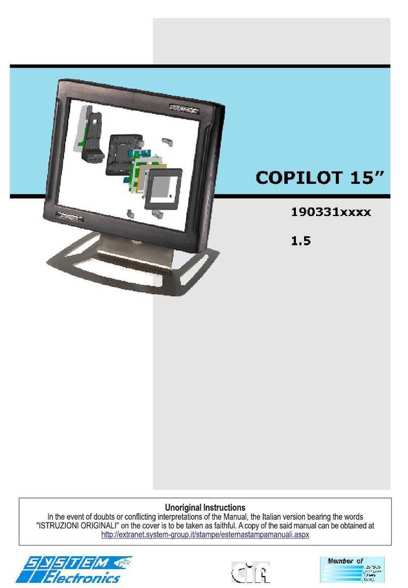
SYSTEM Electronics COPILOT 15" User manual

Index
1. General features . . . . . . . . . . . . . . . . . . . . . . . . . . . . . . . . . . . . . .3
2. Specifications . . . . . . . . . . . . . . . . . . . . . . . . . . . . . . . . . . . . . . . .3
3. The COPILOT - Description and operation . . . . . . . . . . . . . . . . . . .3
3.1 Switching on and off . . . . . . . . . . . . . . . . . . . . . . . . . . . . . . 3
3.2 Rear LED . . . . . . . . . . . . . . . . . . . . . . . . . . . . . . . . . . . . . . 3
3.3 Charge contacts . . . . . . . . . . . . . . . . . . . . . . . . . . . . . . . . . 3
3.4 USB connector . . . . . . . . . . . . . . . . . . . . . . . . . . . . . . . . . . 3
3.5 Touch-screen and display . . . . . . . . . . . . . . . . . . . . . . . . . . . 4
3.6 Batteries . . . . . . . . . . . . . . . . . . . . . . . . . . . . . . . . . . . . . . 4
3.7 Connectivity . . . . . . . . . . . . . . . . . . . . . . . . . . . . . . . . . . . . 4
3.8 Communication with the Docking Station on board the machine 4
3.9 Memory and data storage . . . . . . . . . . . . . . . . . . . . . . . . . . 5
4. Power supply and common function control software . . . . . . . . .6
4.1 Power supply . . . . . . . . . . . . . . . . . . . . . . . . . . . . . . . . . . . 6
4.2 Automatic background and display management . . . . . . . . . . 7
5. Docking Station . . . . . . . . . . . . . . . . . . . . . . . . . . . . . . . . . . . . . . .8
5.1 Options . . . . . . . . . . . . . . . . . . . . . . . . . . . . . . . . . . . . . . . 8
5.2 Connectors . . . . . . . . . . . . . . . . . . . . . . . . . . . . . . . . . . . . . 8
Signal connectors . . . . . . . . . . . . . . . . . . . . . . . . . . . . . . . . 8
Power supply connectors . . . . . . . . . . . . . . . . . . . . . . . . . . . 9
6. Order code . . . . . . . . . . . . . . . . . . . . . . . . . . . . . . . . . . . . . . . . . . .9
7. Other options . . . . . . . . . . . . . . . . . . . . . . . . . . . . . . . . . . . . . . . .9

PAGE
2
INDUSTRIAL PC - COPILOT
ORDER NO. 5906510010DECEMBER 2005 - REV. 1.3
SYSTEM SPA (Electronics Div.) reserves the right to
make changes to the specifications at any time without
giving prior notice. The information contained herein is
correct and reliable. No part of this publication may be
reproduced in any form without prior authorisation from
SYSTEM SPA (Electronics Div).
DICO is a registered trademark of SYSTEM SPA
(Electronics Div).
BITBUS is a registered trademark of Intel Corporation.
IBM is a registered trademark of International Business
Machines Corporation.
Any other product names mentioned in this publication
are the property of their respective manufacturers.
This product meets the EMC requirements
of EEC Directive 89/336.
Revisions Pages
Rev. 1.0 First draft 8
Rev. 1.1 Add Paragraph 4.1 9
Rev. 1.2 Adjournment 9
Rev. 1.3 Add Figure 5.2.3 9
SYSTEM s.p.a. Div. Electronics
via Ghiarola Vecchia, 73
41042 Fiorano (Mo) Italy
tel 0536/836111 - fax 0536/830901
www.system-group.it
e-mail: info.electronics@system-group.it
The manual present applies itself to the following produced codes:
5906510010 COPILOT GEODE 300MHz
5906510015 Docking COPILOT only power supply
5906510035 Docking COPILOT RS232/RS422/CAN with jack for power supply and DB9
5906510045 Docking COPILOT only power supply M12 to 24Vdc
5906510057 COPILOT CELERON 400MHz

PAGE
3
INDUSTRIAL PC - COPILOT
ORDER NO. 5906510010DECEMBER 2005 - REV. 2005
1. General features
COPILOT is SYSTEM Electronics's solution to the
requirements of an advanced, on board graphic interface
with hardwired circuits.
The unit consists of a water and shock resistant portable
terminal, that can easily be transported thanks to the
adjustable handles on the side, and a docking station,
for recharging the batteries and communicating with
equipment connected to the machine. The docking
station is equipped with an emergency stop button which
can be used to switch off the machine, and a release
button that enables the User to disconnect COPILOT.
The release mechanism can be fitted with a lock that
prevents unauthorised personnel from disconnecting the
terminal.
The terminal uses a SVGA 800×600 graphic display and
a resistive touch-screen.
New wireless applications, such as WI-FI, Bluetooth and
IrDA, mean that the COPILOT terminal is completely
mobile.
2. Specifications
• CPU National Geode GX1 300MHz
• CPU CELERON 400MHz
• Display TFT, 10.4" all light readable, SVGA
800×600
• RAM 128MB up to 512MB
• Compact Flash type II up to 2GB
• Hard Disk up to 20GB
• Touch-Screen resistive
•PC104 expansion slot
•6/8 hours battery operation
•4 hours typical recharge time (16 hours in
trickle charge)
• Consumption: 12W max, 2W in stand-by
•24Vdc power supply or 220Vac external supply,
12V power supply on request
•IP67 protection rating, drop shock resistant
• Docking Station with hard-wired safety circuits
and battery charter
• Operating temperature: 0-40 °C
• Dimensions: h=284, l=246, d=77 mm
• Weight: approx 2460g (with 1 battery pack)
approx 2860g (with 2 battery packs)
3. The COPILOT -
Description and
operation
3.1 Switching ON and OFF
The ON/OFF button is located at the rear of COPILOT:
pressing this button for a few seconds switches the CPU
on or off.
If the User attempts to switch the terminal on when it is
not inserted in the docking station, and with the batteries
discharged, a rapid sequence of beeps is emitted,
indicating that the terminal cannot be switched on, and
must be replaced in the station.
Toward the end of the battery autonomy period, the
terminal emits an acoustic signal once every 30 seconds
to indicate that the battery charge level is low; when
the residual charge is exhausted the CPU is switched off
automatically to avoid damaging the batteries.
When COPILOT is replaced in the docking station an
acoustic signal indicates that the correct power supply
is present. Continuous beeps indicate that the power
supply voltage is too low.
3.2 Rear LED
The ON/OFF button is also fitted with a green LED which
is illuminated when the external power supply is present.
This LED flashes at a rate of once per second during
recharge, and at a slower rate during "trickle charging".
3.3 Charge contacts
The four contacts on the rear of the base allow COPILOT
to be recharged even when the base is upside down.
Ensure these contacts stay clean and free from grease.
3.4 USB connector
A sealed, cylindrical plug protects the CPU USB connector
(Ethernet) on the rear panel. Slowly rotate this plug in
order to remove it.
To prevent dirt and humidity from damaging COPILOT,
always re-insert this plug when the connector is not in
use.
Before re-inserting the plug, lubricate it lightly with
Silicon oil so that it is easy to remove the next time.

PAGE
4
INDUSTRIAL PC - COPILOT
ORDER NO. 5906510010DECEMBER 2005 - REV. 1.3
3.5 Touch-Screen and display
The touch-screen permits the User to interact with the
application program by emulating the left-click of a
mouse. The driver for Windows 98/2000/XP also
emulated the right-click, if required by the program, by
pressing the touch-screen for a few seconds. A "virtual
keyboard", running in the Windows environment, is
provided to enable the user to insert data that would
ordinarily have to be typed.
The display brightness can be regulated in order to save
energy and prolong battery life. The display is set to
maximum brightness by pressing the touch-screen, then,
after a few minutes, it reverts to minimum brightness.
Using the management program provided, the User can
alter the display brightness settings: maintaining it at a
fixed brightness, or activating a screensaver.
The display uses a CCFT lamp, with a typical luminosity
of 150 nit and a lifetime of 20.000 hours.
The display resolution is 800×600 pixels, with a reading
angle of ±45° horizonal and ±15° vertical.
3.6 Batteries
COPILOT is supplied with two 7.2V 4100mAh NiMH
battery pack (a single battery for the VIA 667MHz
version).
The power supply includes an advanced battery charger
circuit that optimises battery duration and reduces
deterioration caused by frequent recharging.
The system estimates the remaining battery charge and
communicates it to the CPU via the parallel port or the
COM1 serial port.
The software provided with COPILOT indicates the
remaining charge and shuts down the system before
the CPU is switched off.
The charge level is expressed as a number between 5
(min) and 250 (max).
The batteries are recharged only when they have fallen
below 50%.
The batteries are at the minimum level when the voltage
reaches 1V/cell.
Completely discharged batteries are normally recharged
in 4 hours.
The management program indicates if it is necessary to
"trickle charge" the batteries in order to recondition
them. "Trickle charge", which takes 12 hours, requires
a specific command from the User. COPILOT must be
completely discharged before a trickle charge is
executed.
The current drain depends on the type of charge, and
varies from 0.5A to 1A at 24V.
In the case of 12V versions, a single battery pack is
fitted in the lower compartment: the maximum duration
is reduced to two hours, although recharge times remain
the same.
3.7 Connectivity
COPILOT wireless applications offer a maximum of
flexibility and freedom, enabling the User to control the
machine from a range of locations.
COPILOT has been designed as a universal interface, it
permits the User to communicate with the machine,
receive the required data, as well as the desired manuals,
and update the equipment without difficulty.
Native interfaces:
•USB, connector located on the rear
•IrDA, short-range Infra Red communications with
devices such as telephones, printers and modems
Optional interfaces:
•WI-FI: 2.4GHz wireless radio communications in
conformity with the 802.11b standard, using point-
point or access-point modes. For greater security,
information can be encoded using 64 or 128-bit
WEP. The maximum communication distance
between two units, or between COPILOT and the
access-point is 100m
•Bluetooth interface for short-range
communications with compatible devices
•GPRS: radio modem for permanent connection to
Internet and Email services
•The free PC104 slot can be used to connect special
applications (GPS, tele-camera, GPRS, modem, …).
An ETHERNET connection can be used, as an
alternative to the USB connector on the rear.
3.8 Communication with the
Docking Station on board
the machine
When the unit is recharging, communication between
COPILOT and the machine is possible, depending on the
type of base is use, and the IrDA optical port settings.
When supplied, the Docking Stations are set-up for a
specific communication type, via the IrDA port, and may
use:
•CANbus
•RS232
•RS422
•ID
CANbus mode, where COPILOT can dialog with the
machine units via the CAN UART, enabling the User to
control the command devices directly, and monitor the
machine operating state. CPU CAN communication is
sent through the parallel port and transferred to the
base via the integrated optical port, where it is
reconverted to the CAN ISO 11898-24V standard.
To enable software application transparent
communication with the hardwired devices, the CPU
RS232 can be transferred to the base via the optical
port, and duplicated at a standard DB9 connector on
the rear of the base.
Alternatively, each Docking Station can be assigned a
unique ID number so that they can be identified in a
system consisting of more than one machine, thus
ensuring secure operation.
The Docking Station can also be supplied without any
options, so that it can be used simply as a battery charter.
PAGE
5
INDUSTRIAL PC - COPILOT
ORDER NO. 5906510010DECEMBER 2005 - REV. 2005
The emergency off button on the base ensures maximum
safety during calibration procedures.
3.9 Memory and data storage
COPILOT has a maximum of 512MB of RAM, of which
4MB are reserved as Video RAM. In order to increase
reliability, the hard disk has been replaced with a
Compact-Flash for embedded operating systems that
do not take up a large amount of disk space (Linux,
Dos, Windows XPE).
In the case of Windows 98/NT/2000 operating systems
a micro-drive is installed in the type II Compact-Flash
slot.
The Compact-Flash drives are available at 32MB and
512MB
The maximum capacity of micro-drive currently available
is 2GB.
An extra Compact-Flash slot can be added in order to
increase the capacity of the physical memory.
Figure 3.9.1
Figure 3.9.2

PAGE
6
INDUSTRIAL PC - COPILOT
ORDER NO. 5906510010DECEMBER 2005 - REV. 1.3
4. Power supply and
common function
control software
4.1 Power supply
In order to avoid any communication conflicts, close all
programs that use the serial or the parallel port
(especially if COPILOT Tray is running).
When the "COPILOT Power Supply" program is started,
a dialog window is displayed allowing the User to select
which port to use for communicating with the power
supply board.
Ideal communication conditions are achieved by
selecting the LPT1 port and "No Serial".
Figure 4.1.1
A number of windows can be called up by clicking on
the icons displayed on the screen.
Use the following buttons to regulate the display
brightness:
OFF: to switch off the display
MIN: for minimum brightness
MAX: for maximum brightness
The AUTO mode (default setting) reduces the display
brightness after a few minutes of inactivity, returning
to maximum brightness when the User touches the
screen. The display is not switched off completely in
this mode.
For improved energy saving it is possible to select the
ULTRA AUTOMATIC mode, which reduces brightness
after a few minutes, and switches off the display after
10 minutes. The display brightness when the User
touches the screen.
When in MANUAL mode the brightness remains constant
at the selected level.
Pressing Display Status Request displays the currently
stored state. Each time the system is switched on the
display reverts to the AUTO mode.
Figure 4.1.2
In order to select between IrDA, RS232 and CAN, it
may be necessary to modify the COPILOT optical
communications factory settings.
The following dialog window is used to select between
these settings.
Pressing Get IrDA status displays the current
communication mode:
IrDA Sir (standard) Com1 Null
IrDA Fir (fast) CAN
If COM1 is used for the communications channel it cannot
be used to control the power supply.
Figure 4.1.3
Pressing the battery icon displays the battery charge
level, and other important information such as battery
voltage and temperature.
Figura 4.1.4

PAGE
7
INDUSTRIAL PC - COPILOT
ORDER NO. 5906510010DECEMBER 2005 - REV. 2005
4.2 Automatic background and
display management
This utility, which is normally active when COPILOT is
switched on, is used for managing the display, displaying
the battery charge level, and shutting down Windows
when the On/Off button on the rear panel has been
pressed.
COPILOT TRAY can be personalised according to the
Customer's requirements:
ÆStarting the program from the "Programs" menu Æ
"COPILOT Power Supply" ÆCOPILOT TRAY
Figure 4.2.1
Enables the User to select the following Start-up options:
• Parallel port: the program is configured to use
the LPT1 port, the serial port is disabled.
• Enable Windows Shutdown: enables automatic
shutdown when the button is pressed [it is advised
that this option be enabled].
• Touch-screen Buzzer Disabled: if selected, this
option inhibits the touch-screen confirmation beep.
• Automatic Start-up: this utility is automatically
run from the command line illustrated below when
Windows is started [advised].
• Auto Lum: default display setting: in order to
save batteries and prolong display life, the
brightness is reduced after a few seconds of
inactivity. The brightness is restored to the
maximum level by touching the screen.
• Max Lum: the brightness is always set to
maximum level [not advised].
• Max Lum Only on Docking: automatic brightness
management depending on the type of operation:
when the unit is in the docking station the
brightness is always set to the maximum level,
when it is in portable mode the brightness is
controlled automatically.
•COPILOT shutdown time can be modified to enable
Windows to be shutdown correctly (release 5.20
and later).
•The program informs other applications of the
battery charge level and Windows shutdown via
UDP.
Figure 4.2.2
To avoid occupying CPU resources, the COPILOT Tray
program handles communication with the power supply
via the parallel port, at a rate of approximately once
every two seconds.
Screensaver:
The Windows screensaver may be selected so that the
display lamp can be switched off. Select
ScreenSaveCopilot from the list of screen-savers
available in the Windows menu (Control Panel - Screen).
Use the server mode to communicate with the active
COPILOT TRAY utility, which acts as the power supply
communications server.
Figure 4.2.3
To avoid interfering with other active programs, use the
"via server" communications mode only. The screensaver
can be set-up so that it is always active, or active only
in portable mode, when the unit is not inserted in the
docking station. When the screensaver is activated, after
the preset period, the display is switched off. Touch the
screen to switch the display on again.

PAGE
8
INDUSTRIAL PC - COPILOT
ORDER NO. 5906510010DECEMBER 2005 - REV. 1.3
NOTE:
The screensaver "Preview" switches off the display.
Each time another screensaver is selected from
the Windows menu, the display may switch off
momentarily, in fact, Windows allows the User to
preview the selected screensaver. Simply touch the
screen to restore normal brightness.
5. Docking Station
The Docking Station is used to recharge COPILOT
batteries, in addition, a number of options are provided
that enable COPILOT to interact with the machine via
the Docking Station.
Figure 5.1 Docking Station
5.1 Options
The following additional functions are available:
1) Electromechanical push-buttons: the three
slots on the front panel of the Docking Station can
be used to house electromechanical push-buttons,
that drive a set of contacts on the rear panel
(where the connectors are located).
2) Copilot present: a short-circuit protected, PNP
digital output connected to the external power
supply voltage (0.7A max); it indicates that there
is a Copilot unit is present, either switched on, or
recharging in the Docking Station.
3) Infrared communications: an infrared port is
available for wireless communication with Copilot
in the following modes:
• ID code reading: 5 configurable bits that can
be read by COPILOT, via an invariable serial
command on COM1 (configured as a 9600bps
fixed baud rate infrared port on COPILOT),
enable Copilot to identify the Docking Station in
which it is currently located.
• RS232 data transmission: this permits RS232
serial communication via the COM1 port
(configured as a 115200bps fixed baud rate
infrared port on Copilot). Optical communication
is enabled only if HALF-DUPLEX data exchange is
guaranteed, therefore it is strongly advised that
Xon-Xoff mode not be used, as this could result
in simultaneous data exchange, thereby
compromising optical communications. Three
wire serial communication is used.
• RS422 data transmission: this permits RS422
serial communication via the COM1 port
(configured as a 115200bps fixed baud rate
infrared port on Copilot). Optical communication
is enabled only if HALF-DUPLEX data exchange is
guaranteed, therefore it is strongly advised that
Xon-Xoff mode not be used, as this could result
in simultaneous optical communications.
• CANbus data transmission: this mode enables
communications over CANbus Rev. 2.0 A/B
networks at a maximum frequency of 250Kbps.
The Copilot infrared device must be set to
CANbus mode.
5.2 Connectors
Various types of connectors are available, depending
on the options present on the Docking Station.
Signal connectors
Figure 5.2.1 Docking 5906510035
GND
RX
TX
Connector 9 POLES
MALE

PAGE
9
INDUSTRIAL PC - COPILOT
ORDER NO. 5906510010DECEMBER 2005 - REV. 2005
Power supply connectors
Figure 5.2.2 Docking 5906510035, 5906510015
Figure 5.2.3 Docking 5906510017
6. Order code
5906510010 Copilot Geode 128MB RAM
5906510057 Copilot Celeron 400MHz 256MB RAM
6800000337 Compact Flash Card 32MB
6800000341 Compact Flash Card 64MB
6800000343 Compact Flash Card 256MB
6800000348 Compact Flash Card 512MB
6800000350 Compact Flash Card 1GB
5906510096 Kit adapter Compact Flash
5906511301 Slot for Compact Flash added
6800000344 Microdrive 1GB up to 4GB
5906510048 Kit Hard Disk 20GB
6800000355 USB Wi-Fi Netgear Ma111 V2
W1802.11b 11mb (internal)
6800000345 Modem - Telephone GPRS USB
5906511901 Modem GPRS PC104 board
5906510045 Docking Copilot only power supply
M12 to 24Vdc
5906510015 Docking Copilot only power supply
5906510017 Docking Copilot with power supply
M12 and emergency stop button
5906510035 Docking Copilot RS232/RS422/CAN
with jack for power supply and DB9
8330203100 Support for keyboard for Docking
5906510049 Power kit 220Vac/24V 70W + cable
6800000346 USB 2.0 64MB key
6800001023 Microsoft OEM Windows 98 license
6800001029 Microsoft OEM Windows XP license
VIN+
VIN-
Connector
2 POLES
12
5
43
VIN+
VIN-
Emergency stop button NC
PE
M12 connection
Docking power supply
7. Other options
Bluetooth board internal
Display high brightness
Single battery pack
Rigid suitcase for the transport
ETHERNET connector on the rear COPILOT
Other manuals for COPILOT 15"
2
Table of contents
Other SYSTEM Electronics Industrial PC manuals

SYSTEM Electronics
SYSTEM Electronics COPILOT Monitor 15.6" User manual

SYSTEM Electronics
SYSTEM Electronics COPILOT 15" User manual

SYSTEM Electronics
SYSTEM Electronics PC-188 User manual

SYSTEM Electronics
SYSTEM Electronics COPILOT 15" User manual

SYSTEM Electronics
SYSTEM Electronics COPILOT PB User manual

SYSTEM Electronics
SYSTEM Electronics COPILOT 21.5 User manual