pag.
3
Industrial PC- COPILOT 21.5"
Order code 2E00xxxxNovember 2020 - Rev. 1.8
1. General Features
Copilot 21.5'' is the System Electronics operator panel
that oers performance and performance for all su-
pervisory and on-board machine applications, with an
innovative and robust design and mechanically reliable.
Made of stainless steel, resistant to dust and liquids,
Copilot 21.5'' is a PC solution adaptable to all the needs
of the latest generation industrial machines.
The 1920x1080 FullHD graphic display allows the display
of high resolution images and movies; it is equipped
with user and remote adjustable LED backlighting. The
multi-touch touch screen with up to 10 simultaneous
touches, and scratch-resistant, allows operator inte-
raction with simple gestures.
The Copilot 21.5" PC terminal, thanks to the new in-
tegrated Wireless solutions, can operate as a supervisor
of the equipment connected to the machine and with
users' portable devices.
Dierent congurations, such as solid state disks for
data storage and I/O management make the Copilot
21.5'' adaptable to all the needs of the industrial market.
2. Technical
specication
•CPU: Intel i7-7700T 7th-GEN 2.9GHz
Intel i5 Core 7500T 7th-GEN 2.7GHz
Intel J5005 Quad Core 1.5GHz GeminiLake
Intel J1900 Quad Core 2GHz Bay Trail
• RAM Memory: up to 32GB
• Operating System: Windows 10 Iot, Windows 8.1
64bit, Microsoft Widows Embedded 7, altro a richiesta
• Expansion slot: 1 x miniPCIe / 1x M.2
• LCD:
Size/model: 21,5’’ TFT Color LCD
Maximum resolution: 1920 x 1080 FullHD
Touch Screen: PCAP - 10 tocchi
Brightness: 300 cd/m2
Field of view angle:±89° H, ±89° V
Contrast: 1:5000
• Capacity:
HDD: SATA no a 1TB 2,5’’
SSD: Fino a 256GB
• Input/Output ports:
LAN: 2 Eth 10/100/1000
Serial port: 2 x RS232
Parallela port: internal
PS2 port: Keyboard + Mouse
USB port: Up to 8 x USB - (6 x USB 2.03 + 2 x
USB 3.0)
I/O: Available on request
Wireless connection optional: WiFi 802.11
a/b/g/n + Bluetooth 4.0
Audio: Line in / Line out
Video Output: DVI/VGA/DP
• Battery
Type and duration: UPS available on request
• Caratteristichesiche:
Weight: Max 10 Kg
Size: 545(W) x 335(H) x 85(D) mm
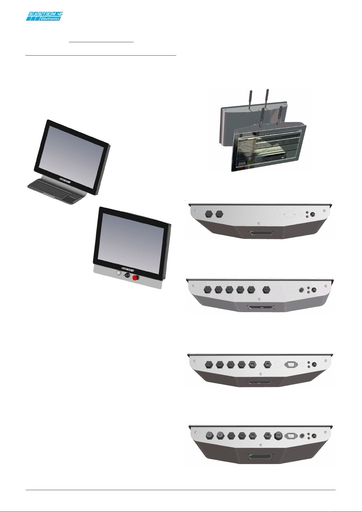
Protection: IP67 - Stainless Steel
Mounting: Arm / Panel
Power supply: 24 Vdc
Temperature: 0°C +50°C
(Max +60°C cooled version)
3. Description and
operation
Copilot 21.5'' can be powered at 24VDC from an exter-
nal power supply or directly from the 24Vdc power supply
of the machine to which it is connected. The PC turns on
automatically when the input power supply is present.
Copilt 21.5'' has two gigabit-ethernet networks, two
RS232 serial ports, PS2 mouse and keyboard port, 4
USB 2.0 ports, display port connection, DVI or external
VGA for a remote monitor, audio connection.
Other communication ports (such as USB3.0, parallel,
etc.) are available as an option.
The main recent operating systems can be pre-installed
on the terminal: Windows 10, Linux Debian9, Windows7
and Windows 8.1.
After the operating system shutdown you can turn on
Copilot 21.5'' again by disconnecting for 10 seconds and
reconnecting the external 24VDC power supply or by
pressing the optional power button. It is also possible
to turn on Copilot 21.5'' from Wake-On-Lan commands
from an external PC connected to the terminal's Ether-
net network.
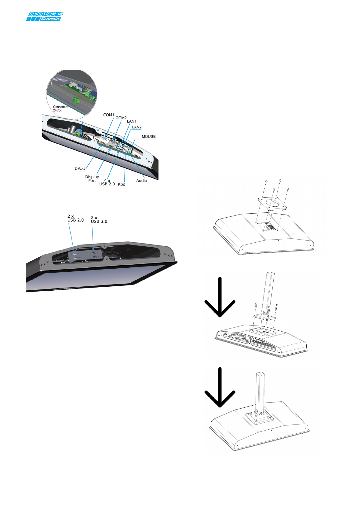
4. Installation
4.1 Configuration of internal
connectors
- Remove the 6 M5 xing screws M5 of the Copilot
21.5'' that cover the upper and lower doors, taking care
to keep the gaskets placed in the screws themselves and
inside the mechanics, in order to reassemble them later
in the same position.
- Typically all the connection cables are connected
from the bottom side of the Copilot 21.5'': the removal of
the upper door can facilitate the insertion of the cables
allowing to control their insertion.
- Nella versione a 8 USB le 4 porte USB aggiuntive
sono poste sotto lo sportello superiore.
- The power connector is placed vertically, acces-
sible by inserting your hand inside the bottom opening.