pag.
3
INDUSTRIAL PC - COPILOT 15,6"
Order 2E00xxxxNovember 2020 - Rev. 1.2
1. General features
Copilot 15,6'' is the operator panel of System Electro-
nics that oers performance for all supervision and
on-board applications, with an innovative and robust
and mechanically reliable design.
Ideal for embedded applications, such as test machines,
measuring and process instruments, industrial applica-
tion monitors, where 24/7 reliability and performance
are reclaimed.
Made of stainless steel, resistant to dust and liquids,
Copilot 15,6'' is a solution that can be adapted to all
the needs of the latest generation of industrial machines.
The 1920x1080 FullHD graphic display allows the display
of high resolution images and movies; It is equipped
with LED backlight adjustable by the user and remotely.
The multitouch touch screen with up to 10 simultaneous
touches, and resistant to scratches, allows operator
interaction with simple gesture.
The PC Copilot 15,6'' terminal, thanks to the new in-
tegrated Wireless solutions, can operate as a supervisor
of the equipment connected to the machine and with
the users' portable devices.
Dierent congurations, such as solid state drives for
data storage and I / O management make the Copilot
15,6'' adaptable to all the needs of the industrial market.
2. Technical
specications
• CPU:
Intel i7 Core i7-7700T 7th-gen 2,9GHz
Intel i5 Core i5-6500TE 6th-gen 2,3GHz
Intel J1900 Quad Core 2GHz Bay Trail
AMD GX-210HA Dual Core 1GHz
• RAM: up to 32GB
• Operating system: Windows 10 iOT, Microsoft
Windows Embedded 7, Windows CE 7.0, Windows
8.1 64bit, other on request
• Expansion slot: 1 x miniPCIe
• LCD:
Size / model: 15,6’’ TFT Color LCD
Max resolution: 1920 x 1080 FullHD
Touch Screen: PCAP - 10 tocchi
Brightness: 400 cd/m2
Field angle: ±85° H, ±85° V
• Storage capacity:
HDD: SATA up to 1TB 2,5’’
SSD: Up to 256GB
• Input/Output:
LAN: 2 Eth 10/100/1000
Serial Doors: 2 x RS232 (RS422/RS485 optional)
PS2 Door: Keyboard + Mouse
• USB: Up to 8 x USB - (6 x USB 2.03 +
2 x USB 3.0)
• I/O: on request
• Optional wireless connection: WiFi 802.11
a/b/g/n + Bluetooth 4.0
Audio: Line in/Line out
Video Output: DVI/VGA
•UPS Uninterruptible power supply available on
request
•On / o button: optional
•Physical characteristics:
Weight: Max 4,5 Kg
Dimension: 392(W) x 242(H) x 75(D) mm
Protection: IP67 - Made of stainless steel
Mounting: Arm / Panel (VESA100 xing)
Color: inox / matt black painted
•Power supply: 24 Vdc - 48 Vdc
•Temperature: 0 °C +50°C
(Max +60°C cooled version)
Storage temperature: -20°C ... +60°C
3.Installation
3.1 Power connection
Copilot 15.6'' can be powered at 24VDC (48VDC for
versions that support it) from an external power supply
or directly from the low voltage power supply of the
machine to which it is connected.
The power supply must be designed to prevent the ma-
ximum voltage from reaching a dangerous level, even
in the presence of a ground fault in other circuits. We
recommend using PELV or SELV power supplies (pro-
tection by extra-low voltage) / (safety extra-low voltage)
according to EN 60950-1 (SELV) || EN 60204 (PELV).
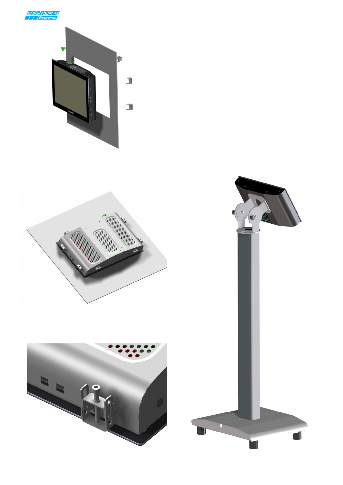
3.2 Connectors layout
Copilot 15.6'' can be installed in the built-in or hanging
version, designed to be connected to a VESA100 arm.
Depending on the conguration chosen, refer to sections
4.1 for the hanging version, and 4.2 for the built-in
version, for a correct installation.