SystemRoMedic ReTurn7600 User manual

Service manual - English
Visual inspection
Check the condition and function of the product regularly. Check to ensure that material is free from damage. If there are
signs of wear, the product must be inspected and serviced.
Always read the manuals for all assistive devices used during a transfer.
Keep the manual where it is accessible to users of the product.
Do not leave the patient unattended during a transfer situation.
The product should be inspected yearly, and otherwise as required, by a qualified technician. Service must be performed
by a qualified technician.
Functional inspection
Always read the manual
Art. no.
7600
Manual no: 720-En Ver. 1 150617
SWL: 205kg/450 lbs
ReTurn7600
SystemRoMedicTM

Table of contents
Assembly.......................................................................................... 3
General................................................................................................... 3
Exploded view ............................................................................. 4-5
Rising ladder and leg support with component list ...................................... 4
Chassie with component list ..................................................................... 5
Spare parts................................................................................... 6-9
Spare part list ...................................................................................... 6-7
Replacing spare parts ........................................................................... 8-9
Periodic inspection.................................................................10-14
Detail descriptions for Periodic inspection.................................................10
Periodic inspection, instruction ...........................................................11-14
Care of the product .................................................................................15
Technical specifications ..........................................................................15
2SystemRoMedicTM

Assembly
A. Push the raising ladder/tube down into the mounting fixture on the
base plate, so that the height-adjustment buttons are facing towards
the caregiver.
B.Insert the wing handles and tighten. Check to ensure that the wing
handles are securely tightened before using the ReTurn.
General
Before the product is used, check to ensure that the screws are securely tightened. The product must be inspected
regularly by an authorized technician. The product must be inspected thoroughly at least once each year, or more
regularly if it is used very frequently. Inspection and service must be performed by an authorized technician.
3
SystemRoMedicTM
A
B

Exploded view - Rising ladder and leg support
Ladder:
Number Name
1 Rasing ladder
Leg support:
Number Name Size
1 Holder for leg support
2 Locking pin
3 Bushing Ø28/Ø25,5x32 mm svart POM
4 Mounting fixture for leg support
5 Screw K6S ISO 7380 M6x16
6 Label SWL
7 Leg support
Components
4SystemRoMedicTM
pos Title Art. nr
1Raising ladder 90001117
SHEET 1 OF 1
D
E
F
C
1234
B
A
321 5
C
D
4678
A
CHK'D
RMD0A0-F_Complete
23.09.2010
B
WEIGHT:
I. Atanasov
A3
SCAL E:1:10
DWG NO.
TITLE:
REVISION
DO NOT SCALE DRAWING
MATERIAL:
DATE
SIGNATURE
NAME
APPV'D
MFG
EDGES
FINISH:
BREAK SHARP
DEBUR AND
Q.A
ANGULAR:
UNLESS OTHERWISE SPECIFIED:
DIMENSIONS ARE IN MILLIMET ERS
SURFACE FINISH:
TOLERANCES:
LINEAR:
DRAWN
1

Number Name Size
1 Base plate
2 Brake pedal left
3 Brake pedal right
4 Brake shoe right
5 Brake shoe left
6 Castors Tente UAP 75
7 Washer Din 125 M10 fzb
8 Screw Din 912 M10x45 fzb
9 Washer Ø16/Ø8,2x2 mm vit POM
10 Center castors, Tente UAP 125 mm
11 Screw Din 24015 8,8 M8x80s22 fzb
12 Nut MHM Din 1587 M8 fzb
13 Washer Ø16/Ø8x1,5 mm
14 Washer Ø20/Ø10x9 mm svart POM
15 Screw MVBF Din 603 M8x30 fzb
16 Screw K6S ISO 7380 M6x20
17 Nut DIN985 M6 fzb
18 Brake shoe antislip
19 Brake pad green
20 Brake pad red
21 Instruction label
22 Label ReTurn7600
Exploded view - Chassie
Components
5
SystemRoMedicTM

Spare parts - Spare part list
Article no. Product Unit Components Images
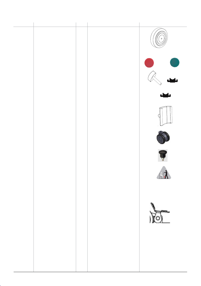
7332 Castors 125mm 1 set 2 x Castor 125mm
2 x Washer
2 x Screw
2 x Nut
7318-10 Brake pads red 1 set 10 x Brake pads red
7319-10 Brake pads green 1 set 10 x Brake pads green
7322 Wing handles 1 set 10 x Wing handle M8x40
10 x Catch for Wing handle
7320 Stop for Wing handle 1 pce 1 x Catch for Wing handle
7321 Wing handle (old version) 1 pce 1 x Wing handle
S/N before xxxxxxxxxx500001
7333 Leg support kit 1 set 1 x Leg support
2 x Mounting fixture for leg support
8 x Screw for bracket M6x16
7331 Castor swirvel 75mm 1 set 4 x Castor swirvel 75mm
4 x Screw
4 x Locking nut
4 x Washer
7326 Locking pins 1 set 10 x Locking pin for leg support
7327 Instruction label 1 set 10 x Instruction label
7328 Brake shoe antislip 0,9 mm 1 set 10 x Brake shoe antislip 0,9
7329 Brake shoe antislip 1,5 mm 1 set 10 x Brake shoe antislip 1,5
7330 Brake kit L and R 1 set 1 x Brake pedal left
1 x Brake pedal right
1 x Brake shoe left
1 x Brake shoe right
2 x Nut MHM Din 1587 M8fzb
2 x Spring washer
2 x Carrier bult
2 x Washer black
2 x Washer white M8
2 x Screw M6x20
2 x Washer white M6
´ 2 x Nut Din 985 M6fzb
2 x Green plastic button
2 x Red plastic button
2 x Friction 3M tape
6SystemRoMedicTM
7318 7319
7322
7333
7331
x 10 x 10
7332
x 10
x 10
7326
x 10
7327
x 10
7320
7330
x 2

Spare part list
Article no. Product Unit Components Images
7334 Carriage bolt / washers 1 set 2 x Carriage bolt M8x35
2 x Teflon coated washer
4 x Steel washer
2 x Locking acorn nut DIN 986
2 x Washer black 7334
x 2
x 2
x 2 x 4 x 2
7
SystemRoMedicTM

Replacing spare parts
Loosen the nut and remove the screw. Install the new wheel, placing the
washer between the wheel and the chassis. Insert the screw and secure it
with the nut.
Centre wheel
Remove the old brakepads and insert the new ones.
Brakepads, red/green
Unscrew the wing knobs and replace them with new ones. If the “stop plate”
needs to be replaced, remove it and replace it with a new one.
Wing handles and stop for wing handles
Unscrew the lower-leg support from its mount. Remove the lower-leg support
and mount, and then install and secure the new ones. The lower-leg support
is secured with 4 screws, which are included in the spare parts kit.
Lower-leg support
5
6
3
8
SCALE 1 : 29
DETAIL B
7
17
18 16
19
11
1
20
21
B
22
8SystemRoMedicTM

Loosen the bolt underneath the swivel wheel, remove it, and then replace all
of the parts for the swivel wheel assembly. Install the new swivel wheel in the
following order: wheel, washer, bolt.
Swivel wheel
Remove the plastic on the locking pin and loosen the nut underneath. The
nut forms a unit with the locking pin, so that when it is loosened, the locking
pin is also removed. Secure the new locking pin and tighten the nut.
Locking pin
For assembly instructions, see page 12 under the Periodic Inspection section.
Antislip brake shoe
For assembly instructions, see page 13 under the Periodic Inspection section.
Brake kit
For assembly instructions, see page 12 under the Periodic Inspection section.
Carriage bolt / washers
9
SystemRoMedicTM

1. Raising ladder Page 8
2. Wing handles Page 8
3. Base plate Page 8
4. Brakes (on fixed wheels) Page 9
5. Fixed castors 125mm and axles (2 pcs.) Page 9
6. Castors 75mm (4 pcs.) Page 10
7. Leg support Page 10
Periodic inspection
Detail descriptions for Periodic inspection
10 SystemRoMedicTM
3
6
5
4
7
2
1

Raising ladder
Check to ensure that there is no visible damage to the raising ladder and that it is
securely mounted in the base plate.
Wing handles
Mount the ladder on the base plate and ensure that both wing handles between
the ladder and undercarriage (2 pcs.) are securely tightened.
Base plate
Turn the ReTurn around and check to ensure that all parts are securely in place.
The gap between the front and rear wheels should be between 2-3 mm.
Park the ReTurn on a level surface and place a 2 mm washer under one of the
castor wheels. The gap can be adjusted with the help of spacers on the castors.
Periodic inspection, instruction
11
SystemRoMedicTM

Brakes
1. Remedial measures to improve brake function:
If braking effect is inadequate, the brake shoes can be switched; alternatively, a strip of anti-slip tape
can be applied to the brake shoe to improve brake function.
Anti-slip is available in two thicknesses: 0.9mm and 1.5mm.
Name of spare part: Brake shoe anti-slip 0.9 mm, Art. No.: 7328
Name of spare part: Brake shoe anti-slip 1.5mm, Art. No.: 7329
Unit: 10 pcs.
Application of anti-slip tape
Note! The ladder should be removed first.
- Unscrew the brake shoe, or remove the wheel to access the
brake shoe surface, and then apply the anti-slip tape to the brake
shoe.
- Check brake function by ensuring that the brake shoe pressure
is adequate when the brake is applied, and that the wheel moves
freely when the brake is released. If the brake shoe is not tight-
ened sufficiently, it may fall down and lock the wheel.
2 To prevent brake pedal from tipping automatically to braking position:
If the brake pedal fails to remain in the raised position, even when the carriage bolt is adjusted, the plastic washer can be
replaced with a steel washer and a Teflon washer to increase tension on the brake pedal. These are placed between the
brake yoke and the chassis. If the washers are replaced, a longer carriage bolt must also be used. (See order of assembly of
parts, below.)
Name of spare part: Carriage bolt/washers, Art. No. 7334
Assembly of washers and carriage bolt
Note! The ladder should be removed first.
Remove the carriage bolt from the brake pedal and replace it with the longer carriage bolt; place the washers between the
brake yoke and the chassis. Ensure that the Teflon side is against the steel washer. The steel washer must be turned so that
the round side is against the Teflon washer. Insert the plastic bushing between the pedal’s yoke and the chassis. Insert the
carriage bolt from the outside. Tighten the locking nut, together with the accompanying steel washer, sufficiently to allow
the right degree of tension on the pedal when the brake is applied and released.
Order of assembly for parts
(marked area)
12 SystemRoMedicTM

3. To improve braking effect and prevent brake pedal from tipping automatically to braking position:
If the brakes do not brake sufficiently and the brake pedal tips automatically to the braking position, the entire brake
system should be replaced with a brake kit. This applies if it is
not possible to remedy the problem by lightly tightening the nut.
Name of spare part: Brake kit H & V, Art. No.: 7330
Assembly of brake kit
Note! The ladder should be removed first.
1. Loosen the nut and remove the brake pedal. 2. If the pedal’s yoke is bent inward, try to bend it back to straighten it.
3. Use a tool, for example, a hex key, to hold the steel washer and Teflon washer in place. Ensure that the Teflon side
is against the steel washer. The steel washer must be turned so that the round side is against the Teflon washer. 4.
Install the pedal and hold the washers in place using the tool. Insert the plastic bushing between the pedal’s yoke and
the chassis, and then insert the tool to hold it in place. 5. Insert the carriage bolt from the underside (the side with the
square hole on the brake yoke) while at the same time drawing out the tool. 6. Tighten the locking nut, together with the
accompanying steel washer, sufficiently to allow the right degree of tension on the pedal when the brake is applied and
released.
Brake pedal
Brake shoe
1. 2. 3.
4. 5. 6.
Order of assembly for parts
13
SystemRoMedicTM

Castor/castor swirvel
Check to ensure that the castor wheel bolts are securely tightened
and that the castors (4 pcs.) rotate and swivel easily. If necessary,
remove dirt and hair from wheels.
Leg support
Check both parallel and horizontal adjustment.
Friction can be adjusted by loosening or tightening the bolts at the
rear of the support.
Castor swirvel
Castor
Castor
Castor swirvel
Castor swirvel
Castor swirvel
14 SystemRoMedicTM

Care of the product:
• Use a soft cloth and mild cleaning agent such as dishwashing liquid or car shampoo to clean the ReTurn. Do not use
abrasive cloths or brushes to clean the base plate.
• Do not use solvents.
• To disinfect, use 70% alcohol.
Technical specifications
• Art.nr 7600 Complete ReTurn
• 7601 Ladder to 7600
SWL, Max weight: 200 kg/440 lbs (static load)
Total weight: 26 kg/57 lbs
Patented
15
SystemRoMedicTM

SystemRoMedicTM
Handicare AB
Maskinvägen 17
SE-972 54 Luleå, SWEDEN
Tel: +46 (0)8-557 62 200
Fax:+46 (0)8-557 62 299
E-mail: [email protected]
www.handicare.com
Handicare AB is quality and environmentcertified in accordance with ISO 9001, ISO14001 and ISO 3485.
Simple solutions for great results
SystemRoMedic™ is the name of Handicare’s unique easy transfer concept, the market’s widest and most
comprehensive range of clever, easy-to-use and safe transfer and lifting aids designed to make life easier, both for the
user and for the caregiver. SystemRoMedic™ is a complete solution that provides for the majority of patient transfer or
manual handling requirements. From the simplest to the most complex scenarios, from the lightest to the heaviest. The
concept encompasses assistive devices for four different categories of transfers:
• Transfer, assistive devices for manual transfers of users between two locations.
• Positioning, assistive devices for manual repositioning of users within the same location.
• Support, assistive devices for mobility support e.g., during sit-to-stand or gait training.
• Lifting, assistive devices for manual and mechanical lifting of users.
Improved work environment, improved quality of care and cost savings
The philosophy behind SystemRoMedic™ is focused on the prevention and reduction of occupational injuries while
allowing users to experience a greater sense of independence and dignity. Through a unique combination of training and
a complete range of efficient transfer aids, SystemRoMedic™ offers improvement of both work environment and quality
of care and, at the same time, achieves significant cost savings.
Always make sure that you have the correct version of the manual
The most recent version of all manuals are available for downloading at/from our website; www.handicare.com.
For questions about the product and its use
Please contact your local Handicare and SystemRoMedic™ representative. A complete list of all our partners with their
contact details can be found on our website; www.handicare.com.
Handicare offers solutions and support to increase the independence of disabled or elderly people as well as to improve the convenience of those who
are caring for them.
The Handicare Group is one of the leading healthcare companies in Europe with its own manufacturing organizations and sales companies
in Norway, Sweden, Denmark, Germany, the Netherlands, Great Britain, France, China, Canada and the USA. Handicare’s products are also
distributed by partners in more than 40 countries worldwide. Our wide range of high-quality products includes various manual and power
wheelchairs, seating systems, scooters, a complete easy transfer system and other patient handling aids, stairlifts, car adaptations, rise and
recline chairs, and bathing and toileting products.
Table of contents
Other SystemRoMedic Medical Equipment manuals