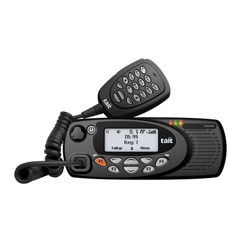
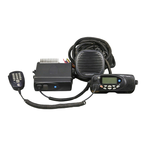
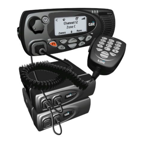
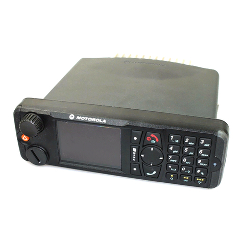
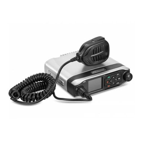
Tait TM8000 Series Instructions for use

TM8000 mobiles
TM8000 3DK Hardware Developer’s Kit
Application Manual
MMAA30-01-00-807 Version 1.01a (TEA)
September 2003 © Tait Electronics Ltd

2TM8000 3DK Hardware Developer’s Kit Application Manual
September 2003 © Tait Electronics Ltd
Contact Information
Tait Radio Communications http://www.taitworld.com
Corporate Head ffice
New Zealand
Tait Electronics Ltd
P.O. Box 1645
Christchurch
New Zealand
E- ail: info@taitworld.co
Website: http://www.taitworld.co
Technical Support:
E- ail: support@taitworld.co
Website: http://support.taitworld.co
Tait North America
Regional Head Office -
United States of A erica
Tait North A erica Inc
E- ail: usa@taitworld.co
Canada
Tait North A erica Inc
E- ail: canada@taitworld.co
Tait Latin America
Tait Latin A erica
E- ail: latina erica@taitworld.co
Tait Europe
Regional Head Office - United Kingdo
Tait Mobile Radio Ltd
E- ail: [email protected].uk
Tait North Asia
Regional Head Office - Hong Kong
Tait Mobile Radio (Hong Kong) Ltd
E- ail: hongkong@taitworld.co
Beijing
Tait Mobile Radio (Hong Kong) Ltd
E- ail: beijing@taitworld.co
Tait South Asia
Regional Head Office - Singapore
Tait Electronics (Far East) Pte Ltd
E- ail: singapore@taitworld.co
Thailand
Tait Mobile Radio Ltd
E- ail: thailand@taitworld.co
Tait ceania
New Zealand
Tait Co unications Ltd
E- ail: [email protected].nz
Australia
Tait Electronics (Aust) Pty Ltd
E- ail: australia@taitworld.co
Note: For the addresses and phone nu bers
of the above regional offices refer to the
TaitWorld website.

TM8000 3DK Hardware Developer’s Kit Application Manual 3
September 2003 © Tait Electronics Ltd
Tait General Software Licence Agreement
This legal docu ent is an Agree ent between
you (the “Licensee”) and Tait Electronics
Li ited (“Tait”). By using any of the Software
or Fir ware ite s prior-installed in the
related Tait product, included on this CD or
downloaded fro the Tait website,
(hereinafter referred to as “the Software or
Fir ware”) you agree to be bound by the
ter s of this Agree ent. If you do not agree
to the ter s of this Agree ent, do not install
and use any of the Software or Fir ware.
If you install and use any of the Software or
Fir ware that will be dee ed to be
acceptance of the ter s of this licence
agree ent.
The ter s of this agree ent shall apply
subject only to any express written ter s of
agree ent to the contrary between Tait and
the Licensee.
Licence
TAIT GRANTS TO YOU AS LICENSEE THE NON-
EXCLUSIVE RIGHT TO USE THE SOFTWARE OR
FIRMWARE ON A SINGLE MACHINE PROVIDED
YOU MAY ONLY:
1. COPY THE SOFTWARE OR FIRMWARE INTO
ANY MACHINE READABLE OR PRINTED FORM
FOR BACKUP PURPOSES IN SUPPORT OF YOUR
USE OF THE PROGRAM ON THE SINGLE MACHINE
(CERTAIN PROGRAMS, HOWEVER, MAY INCLUDE
MECHANISMS TO LIMIT OR INHIBIT COPYING,
THEY ARE MARKED “COPY PROTECTED”),
PROVIDED THE COPYRIGHT NOTICE MUST BE
REPRODUCED AND INCLUDED ON ANY SUCH
COPY OF THE SOFTWARE OR FIRMWARE;
AND / OR
2. MERGE IT INTO ANOTHER PROGRAM FOR
YOUR USE ON THE SINGLE MACHINE (ANY
PORTION OF ANY SOFTWARE OR FIRMWARE
MERGED INTO ANOTHER PROGRAM WILL
CONTINUE TO BE SUBJECT TO THE TERMS AND
CONDITIONS OF THIS AGREEMENT).
THE LICENSEE MAY NOT DUPLICATE, MODIFY,
REVERSE COMPILE OR REVERSE ASSEMBLE ANY
SOFTWARE OR FIRMWARE IN WHOLE OR PART.
Title to Software
THIS AGREEMENT DOES NOT CONSTITUTE A
CONTRACT OF SALE IN RELATION TO THE
SOFTWARE OR FIRMWARE SUPPLIED TO THE
LICENSEE. NOT WITHSTANDING THE LICENSEE
MAY OWN THE MAGNETIC OR OTHER PHYSICAL
MEDIA ON WHICH THE SOFTWARE OR
FIRMWARE WAS ORIGINALLY SUPPLIED, OR HAS
SUBSEQUENTLY BEEN RECORDED OR FIXED, IT IS
A FUNDAMENTAL TERM OF THIS AGREEMENT
THAT AT ALL TIMES TITLE AND OWNERSHIP OF
THE SOFTWARE OR FIRMWARE, WHETHER ON
THE ORIGINAL MEDIA OR OTHERWISE, SHALL
REMAIN VESTED IN TAIT OR THIRD PARTIES
WHO HAVE GRANTED LICENCES TO TAIT.
Term and Termination
THIS LICENCE SHALL BE EFFECTIVE UNTIL
TERMINATED IN ACCORDANCE WITH THE
PROVISIONS OF THIS AGREEMENT. THE LICENSEE
MAY TERMINATE THIS LICENCE AT ANY TIME BY
DESTROYING ALL COPIES OF THE SOFTWARE OR
FIRMWARE AND ASSOCIATED WRITTEN
MATERIALS. THIS LICENCE WILL BE TERMINATED
AUTOMATICALLY AND WITHOUT NOTICE FROM
TAIT IN THE EVENT THAT THE LICENSEE FAILS TO
COMPLY WITH ANY TERM OR CONDITION OF
THIS AGREEMENT. THE LICENSEE AGREES TO
DESTROY ALL COPIES OF THE SOFTWARE OR
FIRMWARE AND ASSOCIATED WRITTEN
MATERIALS IN THE EVENT OF SUCH
TERMINATION.
Limited Warranty
THE SOFTWARE OR FIRMWARE IS SUPPLIED BY
TAIT AND ACCEPTED BY THE LICENSEE “AS IS”
WITHOUT WARRANTY OF ANY KIND EITHER
EXPRESSED OR IMPLIED, INCLUDING BUT NOT
BEING LIMITED TO ANY IMPLIED WARRANTIES AS
TO MERCHANTABILITY OR FITNESS FOR ANY
PARTICULAR PURPOSE. THE LICENSEE
ACKNOWLEDGES THAT THE SOFTWARE OR
FIRMWARE IS USED BY IT IN BUSINESS AND
ACCORDINGLY TO THE MAXIMUM EXTENT
PERMITTED BY LAW NO TERMS OR WARRANTIES
WHICH ARE IMPLIED BY LEGISLATION SHALL
APPLY TO THIS AGREEMENT. TAIT DOES NOT
WARRANT THAT THE FUNCTIONS CONTAINED
IN THE SOFTWARE OR FIRMWARE WILL MEET
THE LICENSEE’S REQUIREMENTS OR THAT THE
OPERATION OF THE SOFTWARE OR FIRMWARE
WILL BE UNINTERRUPTED OR ERROR FREE.

4TM8000 3DK Hardware Developer’s Kit Application Manual
September 2003 © Tait Electronics Ltd
Exclusion of Liability
TAIT’S ENTIRE LIABILITY AND THE LICENSEE’S
EXCLUSIVE REMEDY SHALL BE THE FOLLOWING:
1. IN NO CIRCUMSTANCES SHALL TAIT BE
UNDER ANY LIABILITY TO THE LICENSEE, OR
ANY OTHER PERSON WHATSOEVER, FOR ANY
DIRECT OR CONSEQUENTIAL DAMAGE ARISING
OUT OF OR IN CONNECTION WITH ANY USE OR
INABILITY OF USING THE SOFTWARE OR
FIRMWARE.
2. TAIT WARRANTS THE OPERATION OF THE

SOFTWARE OR FIRMWARE ONLY WITH THE
OPERATING SYSTEM FOR WHICH IT WAS
DESIGNED. USE OF THE SOFTWARE OR
FIRMWARE WITH AN OPERATING SYSTEM
OTHER THAN THAT FOR WHICH IT WAS
DESIGNED MAY NOT BE SUPPORTED BY TAIT,
UNLESS OTHERWISE EXPRESSLY AGREED BY
TAIT.
General
THE LICENSEE CONFIRMS THAT IT SHALL
COMPLY WITH THE PROVISIONS OF LAW IN
RELATION TO THE SOFTWARE OR FIRMWARE.
Law and Jurisdiction
THIS AGREEMENT SHALL BE SUBJECT TO AND
CONSTRUED IN ACCORDANCE WITH
NEW ZEALAND LAW AND DISPUTES BETWEEN
THE PARTIES CONCERNING THE PROVISIONS
HEREOF SHALL BE DETERMINED BY THE NEW
ZEALAND COURTS OF LAW. PROVIDED HOWEVER
TAIT MAY AT ITS ELECTION BRING PROCEEDINGS
FOR BREACH OF THE TERMS HEREOF OR FOR
THE ENFORCEMENT OF ANY JUDGEMENT IN
RELATION TO A BREACH OF THE TERMS HEREOF
IN ANY JURISDICTION TAIT CONSIDERS FIT FOR
THE PURPOSE OF ENSURING COMPLIANCE WITH
THE TERMS HEREOF OR OBTAINING RELIEF FOR
BREACH OF THE TERMS HEREOF.
No Dealings
THE LICENSEE MAY NOT SUBLICENSE, ASSIGN OR
TRANSFER THE LICENCE OR THE PROGRAM
EXCEPT AS EXPRESSLY PROVIDED IN THIS
AGREEMENT. ANY ATTEMPT OTHERWISE TO
SUBLICENSE, ASSIGN OR TRANSFER ANY OF THE
RIGHTS, DUTIES OR OBLIGATIONS HEREUNDER
IS VOID.
No ther Terms
THE LICENSEE ACKNOWLEDGES THAT IT HAS
READ THIS AGREEMENT, UNDERSTANDS IT AND
AGREES TO BE BOUND BY ITS TERMS AND
CONDITIONS. THE LICENSEE FURTHER AGREES
THAT SUBJECT ONLY TO ANY EXPRESS WRITTEN
TERMS OF AGREEMENT TO THE CONTRARY
BETWEEN TAIT AND THE LICENSEE THIS IS THE
COMPLETE AND EXCLUSIVE STATEMENT OF THE
AGREEMENT BETWEEN IT AND TAIT IN
RELATION TO THE SOFTWARE OR FIRMWARE
WHICH SUPERSEDES ANY PROPOSAL OR PRIOR
AGREEMENT, ORAL OR WRITTEN AND ANY
OTHER COMMUNICATIONS BETWEEN THE
LICENSEE AND TAIT RELATING TO THE
SOFTWARE OR FIRMWARE.

TM8000 3DK Hardware Developer’s Kit Application Manual 5
September 2003 © Tait Electronics Ltd
Contents
Contact Information . . . . . . . . . . . . . . . . . . . . . . . . . . . . . . . . . . . . . . . . 2
Tait General Software Licence Agreement . . . . . . . . . . . . . . . . . . . . . . . . . 3
Preface . . . . . . . . . . . . . . . . . . . . . . . . . . . . . . . . . . . . . . . . . . . . . . . . . 8
Scope of Manual. . . . . . . . . . . . . . . . . . . . . . . . . . . . . . . . . . . . . . . . . . . . . . . . . 8
Enquiries and Co ents . . . . . . . . . . . . . . . . . . . . . . . . . . . . . . . . . . . . . . . . . . 8
Updates of Manual and Equip ent . . . . . . . . . . . . . . . . . . . . . . . . . . . . . . . . . . . 8
Copyright. . . . . . . . . . . . . . . . . . . . . . . . . . . . . . . . . . . . . . . . . . . . . . . . . . . . . . 8
Disclai er . . . . . . . . . . . . . . . . . . . . . . . . . . . . . . . . . . . . . . . . . . . . . . . . . . . . . 9
Associated Docu entation . . . . . . . . . . . . . . . . . . . . . . . . . . . . . . . . . . . . . . . . . 9
Publication Record. . . . . . . . . . . . . . . . . . . . . . . . . . . . . . . . . . . . . . . . . . . . . . . 9
Alert Notices . . . . . . . . . . . . . . . . . . . . . . . . . . . . . . . . . . . . . . . . . . . . . . . . . . 10
Abbreviations . . . . . . . . . . . . . . . . . . . . . . . . . . . . . . . . . . . . . . . . . . . . . . . . . . 10
1 Introduction . . . . . . . . . . . . . . . . . . . . . . . . . . . . . . . . . . . . . . . . . . 13
2 escription of the Radio Interfaces . . . . . . . . . . . . . . . . . . . . . . . . . . 15
2.1 RF Connector . . . . . . . . . . . . . . . . . . . . . . . . . . . . . . . . . . . . . . . . . . . . 18
2.2 Power Connector . . . . . . . . . . . . . . . . . . . . . . . . . . . . . . . . . . . . . . . . . . 18
2.3 Auxiliary Connector . . . . . . . . . . . . . . . . . . . . . . . . . . . . . . . . . . . . . . . . 20
2.4 Internal Options Connector. . . . . . . . . . . . . . . . . . . . . . . . . . . . . . . . . . . 28
2.5 Provision for External Options Connector . . . . . . . . . . . . . . . . . . . . . . . . 31
2.6 Provision for Additional Connector . . . . . . . . . . . . . . . . . . . . . . . . . . . . . 31
2.7 Control-Head Connector . . . . . . . . . . . . . . . . . . . . . . . . . . . . . . . . . . . . 32
2.8 Microphone Connector. . . . . . . . . . . . . . . . . . . . . . . . . . . . . . . . . . . . . . 36
2.9 Progra ing Connector. . . . . . . . . . . . . . . . . . . . . . . . . . . . . . . . . . . . . 37
3 Programmable I/O Lines . . . . . . . . . . . . . . . . . . . . . . . . . . . . . . . . . 39
3.1 Digital Input Lines . . . . . . . . . . . . . . . . . . . . . . . . . . . . . . . . . . . . . . . . . 39
3.1.1 Toggle Stand-by Mode . . . . . . . . . . . . . . . . . . . . . . . . . . . . . . 44
3.1.2 Power Sense (Ignition). . . . . . . . . . . . . . . . . . . . . . . . . . . . . . . 44
3.1.3 Enter E ergency Mode . . . . . . . . . . . . . . . . . . . . . . . . . . . . . . 45
3.1.4 Send Channel Preset Call . . . . . . . . . . . . . . . . . . . . . . . . . . . . . 46
3.1.5 Send Free For at Preset 1 . . . . . . . . . . . . . . . . . . . . . . . . . . . . 47
3.1.6 External PTT 1 and 2 . . . . . . . . . . . . . . . . . . . . . . . . . . . . . . . 48
3.1.7 Inhibit PTT. . . . . . . . . . . . . . . . . . . . . . . . . . . . . . . . . . . . . . . 49
3.1.8 Toggle Tx RF Inhibit . . . . . . . . . . . . . . . . . . . . . . . . . . . . . . . 50
3.1.9 Decre ent Channel. . . . . . . . . . . . . . . . . . . . . . . . . . . . . . . . . 51
3.1.10 Incre ent Channel . . . . . . . . . . . . . . . . . . . . . . . . . . . . . . . . . 52
3.1.11 Ho e Channel . . . . . . . . . . . . . . . . . . . . . . . . . . . . . . . . . . . . 53
3.1.12 BCD Pin 0 to 4 . . . . . . . . . . . . . . . . . . . . . . . . . . . . . . . . . . . . 54

6TM8000 3DK Hardware Developer’s Kit Application Manual
September 2003 © Tait Electronics Ltd
3.1.13 Preset Channel . . . . . . . . . . . . . . . . . . . . . . . . . . . . . . . . . . . . 56
3.1.14 Mute External Audio Input . . . . . . . . . . . . . . . . . . . . . . . . . . . 57
3.1.15 Mute Audio Output Path . . . . . . . . . . . . . . . . . . . . . . . . . . . . 58
3.1.16 Un ute Audio Output Path . . . . . . . . . . . . . . . . . . . . . . . . . . 59
3.1.17 Force Audio PA On . . . . . . . . . . . . . . . . . . . . . . . . . . . . . . . . 60
3.1.18 Force Audio PA Off . . . . . . . . . . . . . . . . . . . . . . . . . . . . . . . . 61
3.1.19 Si ulate F1 to F4 Key . . . . . . . . . . . . . . . . . . . . . . . . . . . . . . . 62
3.1.20 Toggle F1 to F4 Key LED . . . . . . . . . . . . . . . . . . . . . . . . . . . . 63
3.2 Digital Output Lines . . . . . . . . . . . . . . . . . . . . . . . . . . . . . . . . . . . . . . . . 64
3.2.1 Busy Status . . . . . . . . . . . . . . . . . . . . . . . . . . . . . . . . . . . . . . . 69
3.2.2 Radio Trans ission Status . . . . . . . . . . . . . . . . . . . . . . . . . . . . 70
3.2.3 Channel Locked Status . . . . . . . . . . . . . . . . . . . . . . . . . . . . . . 71
3.2.4 Reflected PTT Status . . . . . . . . . . . . . . . . . . . . . . . . . . . . . . . 71
3.2.5 External Alert 1 and 2 . . . . . . . . . . . . . . . . . . . . . . . . . . . . . . . 72
3.2.6 Reflected PTT Inhibit Status . . . . . . . . . . . . . . . . . . . . . . . . . . 73
3.2.7 Signalling Audio Mute Status . . . . . . . . . . . . . . . . . . . . . . . . . . 73
3.2.8 Monitor Status . . . . . . . . . . . . . . . . . . . . . . . . . . . . . . . . . . . . 74
3.2.9 Hookswitch Status. . . . . . . . . . . . . . . . . . . . . . . . . . . . . . . . . . 74
3.2.10 Call Setup Status . . . . . . . . . . . . . . . . . . . . . . . . . . . . . . . . . . . 75
3.2.11 Control Status Rx (Line 1 to 3) . . . . . . . . . . . . . . . . . . . . . . . . 76
3.2.12 Inband Tone Received . . . . . . . . . . . . . . . . . . . . . . . . . . . . . . 77
3.2.13 Radio Stunned . . . . . . . . . . . . . . . . . . . . . . . . . . . . . . . . . . . . 77
3.2.14 F1 to F4 Key Status . . . . . . . . . . . . . . . . . . . . . . . . . . . . . . . . . 78
3.2.15 FFSK Data Received Status . . . . . . . . . . . . . . . . . . . . . . . . . . . 79
3.3 Audio Tap In and Tap Out Lines . . . . . . . . . . . . . . . . . . . . . . . . . . . . . . 80
4 Creating Your Own Options Board . . . . . . . . . . . . . . . . . . . . . . . . . . 85
4.1 Internal Options Board . . . . . . . . . . . . . . . . . . . . . . . . . . . . . . . . . . . . . . 85
4.1.1 Mechanical Envelope. . . . . . . . . . . . . . . . . . . . . . . . . . . . . . . . 86
4.1.2 TM8000 Internal Options Kit . . . . . . . . . . . . . . . . . . . . . . . . . 89
4.1.3 Co on Practices for Internal Options Board Design . . . . . . . 90
4.1.4 Guidelines for EMC Design. . . . . . . . . . . . . . . . . . . . . . . . . . . 91
4.2 Blank Control Head Options Board. . . . . . . . . . . . . . . . . . . . . . . . . . . . . 95
5 Connecting Third-Party Products . . . . . . . . . . . . . . . . . . . . . . . . . . . 97
5.1 External Products . . . . . . . . . . . . . . . . . . . . . . . . . . . . . . . . . . . . . . . . . . 98
5.1.1 External Mode . . . . . . . . . . . . . . . . . . . . . . . . . . . . . . . . . . . 98
5.1.2 Audio Headset . . . . . . . . . . . . . . . . . . . . . . . . . . . . . . . . . . . 102
5.1.3 USB Adaptor . . . . . . . . . . . . . . . . . . . . . . . . . . . . . . . . . . . . 106
5.2 Internal Products . . . . . . . . . . . . . . . . . . . . . . . . . . . . . . . . . . . . . . . . . 107
5.2.1 Encryption Module (Scra bler) . . . . . . . . . . . . . . . . . . . . . . . 107
5.2.2 ANI Module . . . . . . . . . . . . . . . . . . . . . . . . . . . . . . . . . . . . . 113
6 Replacing the Tait T2000-A81 Board . . . . . . . . . . . . . . . . . . . . . . . . .117
6.1 Differences Between the TM8000 and T2000-A81 Interfaces . . . . . . . . . 117
6.2 Configuring the TM8000 . . . . . . . . . . . . . . . . . . . . . . . . . . . . . . . . . . . 118

TM8000 3DK Hardware Developer’s Kit Application Manual 7
September 2003 © Tait Electronics Ltd
7 Power Sense Options . . . . . . . . . . . . . . . . . . . . . . . . . . . . . . . . . . . .121
7.1 13.8V Battery Power Sense . . . . . . . . . . . . . . . . . . . . . . . . . . . . . . . . . . 123
7.2 Auxiliary Power Sense (Ignition Sense) . . . . . . . . . . . . . . . . . . . . . . . . . 124
7.3 Internal Options Power Sense . . . . . . . . . . . . . . . . . . . . . . . . . . . . . . . . 124
7.4 No Power Sense (On/Off Key Only). . . . . . . . . . . . . . . . . . . . . . . . . . . 125
7.5 E ergency Power Sense . . . . . . . . . . . . . . . . . . . . . . . . . . . . . . . . . . . . 125
7.6 Configuring the Hardware Links LK1 to LK4. . . . . . . . . . . . . . . . . . . . . 126
7.7 Radio Progra ing . . . . . . . . . . . . . . . . . . . . . . . . . . . . . . . . . . . . . . . 130
8 Connector Power Supply Options . . . . . . . . . . . . . . . . . . . . . . . . . . .131
9 Connecting an External Alert evice . . . . . . . . . . . . . . . . . . . . . . . . .133
9.1 Fitting Power MOSFET Q707 and Re oving Resistor R768 . . . . . . . . 134
9.2 Radio Progra ing . . . . . . . . . . . . . . . . . . . . . . . . . . . . . . . . . . . . . . . 135
9.3 Connecting the External Alert Device . . . . . . . . . . . . . . . . . . . . . . . . . . 135

8TM8000 3DK Hardware Developer’s Kit Application Manual
September 2003 © Tait Electronics Ltd
Preface
Scope of Manual
This anual contains a description of the radio interfaces and infor ation
on how to integrate third-party products and create internal and control-
head options boards for TM8105 and TM8115 radios.
Enquiries and Comments
If you have any enquiries regarding this anual, or any co ents, suggestions
and notifications of errors, please contact Technical Support, Tait Electronics
Ltd, Christchurch, New Zealand (refer to
“Contact Infor ation” on
page 2
).
Purchase of the 3DK Hardware Developer’s Kit entitles you to telephone
support by your regional Tait service organisation (for telephone nu bers
refer to the TaitWorld website). Tait also offers the ability to log questions via
the internet using the Tait FOCUS call anage ent syste . Please contact
your local Tait service organisation for login details. The Tait FOCUS syste s
allows you to raise technical enquiries directly on Tait via the Internet and
view the progress of that issue through to resolution. This application allows
you to contribute to the issue resolution and also upload and download any
required files to speed up the proble resolution process.
Updates of Manual and Equipment
In the interests of i proving the perfor ance, reliability or servicing of the
equip ent, Tait Electronics Ltd reserves the right to update the equip ent or
this anual or both without prior notice.
Copyright
All infor ation contained in this anual is the property of Tait Electronics
Ltd. All rights are reserved. This anual ay not, in whole or in part, be
copied, photocopied, reproduced, translated, stored, or reduced to any
electronic ediu or achine-readable for , without prior written
per ission fro Tait Electronics Li ited.
All trade na es referenced are the service ark, trade ark or registered
trade ark of the respective anufacturers.

TM8000 3DK Hardware Developer’s Kit Application Manual 9
September 2003 © Tait Electronics Ltd
Disclaimer
There are no warranties extended or granted by this anual. Tait Electronics
Ltd. accepts no responsibility for da age arising fro use of the infor ation
contained in the anual or of the equip ent and software it describes.
It is the responsibility of the user to ensure that use of such infor ation,
equip ent and software co plies with the laws, rules and regulations of the
applicable jurisdictions.
Important Modifications to radio-frequency trans itting equip ent
can void the user's authority to operate the equip ent.
By distributing the TM8000 3DK Hardware Developer’s
Kit, Tait Electronics Ltd. does not accept liability for any
non-co pliance or infringe ent of intellectual property
rights resulting fro the application or use of this kit or
infor ation. Any person odifying Tait radio-frequency
trans itting equip ent is responsible for ensuring that the
odified equip ent eets all legal and regulatory require-
ents in the country of use or supply.
Associated Documentation
TM8100 Mobile Radio User’s Guide (MM8100-00-03-804)
TM8100 Mobile Radio Service Manual (MM8100-02-00-812)
TM8100 Mobile Radio Accessories Manual (MMAA00-00-00-812)
TMAA30-02 TM8000 3DK Application Board Service Manual
(MMAA30-02-00-812)
TMAA30-02 TM8000 3DK Application Board Software Manual
(MMAA30-02-00-429)
TM8100 Co puter-Controlled Data Interface (CCDI) Protocol Manual
(MM8100-00-00-441)
Publication Record
Issue Publication Date Description
1 eptember 2003 1st release

10 TM8000 3DK Hardware Developer’s Kit Application Manual
September 2003 © Tait Electronics Ltd
Alert Notices
Within this anual, four types of alerts are given to the reader: warning,
caution, i portant and note. The following paragraphs illustrate each type
of alert and its associated sy bol.
Warning!! This alert is used when there is a potential risk
of death or serious injury.
Caution This alert is used when there is the risk of minor or
moderate injury to people.
Important This alert is used to warn about the risk of equip ent da -
age or alfunction.
Note This alert is used to highlight infor ation that is required to
ensure that procedures are perfor ed correctly.
Abbreviations
Abbreviation Description
3DK Third-Party Developer’s Kit
AGND Analogue Ground
ALC Automatic Level Control
ANI Automatic Number Identification
AUD Audio
AUX Auxiliary
BCD Binary-Coded Decimal
BIN Binary
BNC Bayonet Neill Concelman (RF connector)
CCDI Computer-Controlled Data Interface
CH Control Head
CMO Complementary Metal Oxide emiconductor
COM Communication (Port)
CT Clear to end
DGND Digital Ground
D P Digital ignal Processor
DTE Data Terminal Equipment
EMC Electromagnetic Compatibility
E D Electrostatic Discharge
E R Equivalent eries Resistance
FF K Fast Frequency hift Keying
GND Ground

TM8000 3DK Hardware Developer’s Kit Application Manual 11
September 2003 © Tait Electronics Ltd
GPIO General Purpose Input/Output
GP Global Positioning ystem
I/O Input/Output
IOP Internal Options Port
IPN Internal Part Number
LED Light-Emitting Diode
LK1…LK4 Hardware Link 1…4
L B Least ignificant Bit
MB Medium Band
MIC Microphone
N/A Not Applicable
NB Narrow Band
NMEA National Marine Electronics Association
OTAR Over-the-Air Rekeying
PA Power Amplifier
PCB Printed Circuit Board
PRG Program
P U Power upply Unit
PTT Press To Talk
RF Radio Frequency
R D Rated ystem Deviation
R I Received ignal trength Indicator
RT Request to end
Rx Receive
RXD Receive Data
/N ignal/Noise
CADA upervisory Control and Data Acquisition
DM hort Data Message
MD urface-Mounted Device
PK peaker
TTL Transistor-Transistor Logic
Tx Transmit
TXD Transmit Data
UART Universal Asynchronous Receiver/Transmitter
U B Universal erial Bus
WB Wide Band
Abbreviation Description

12 TM8000 3DK Hardware Developer’s Kit Application Manual
September 2003 © Tait Electronics Ltd

TM8000 3DK Hardware Developer’s Kit Application Manual Introduction 13
September 2003 © Tait Electronics Ltd
1Introduction
This anual provides you with the infor ation required to:
■interface to the radio and configure the progra able I/O lines:
■“Description of the Radio Interfaces” on page 15
■“Progra able I/O Lines” on page 39
■build your own options boards:
■“Creating Your Own Options Board” on page 85
■interface application devices:
■“Description of the Radio Interfaces” on page 15
■“Progra able I/O Lines” on page 39
■“Connecting Third-Party Products” on page 97
■connect an external alar to the radio:
■“Connecting an External Alert Device” on page 133
■configure the radio for different power configurations:
■“Power Sense Options” on page 121
■“Connector Power Supply Options” on page 131
■“Description of the Radio Interfaces” on page 15
■“Progra able I/O Lines” on page 39
■replace a T2000 radio and a T2000-A81 board with a TM8100 radio:
■“Replacing the Tait T2000-A81 Board” on page 117
■“Description of the Radio Interfaces” on page 15
■“Progra able I/O Lines” on page 39
Refer to the technical support website for the latest infor ation on the
integration of application devices (refer to “Contact Infor ation” on
page 2).

14 Introduction TM8000 3DK Hardware Developer’s Kit Application Manual
September 2003 © Tait Electronics Ltd

TM8000 3DK Hardware Developer’s Kit Application Manual Description of the Radio Interfaces 15
September 2003 © Tait Electronics Ltd
2 Description of the Radio Interfaces
This chapter describes the characteristics of the echanical and electrical
interfaces of the radio body and the TM8115 control head or the TM8105
blank control head, which are suitable for the connection of TM8000 or
application accessories and equip ent.
Figure 2.1 provides an overview of the TM8000 interfaces:
Figure 2.2 shows the connectors of the radio body.
Figure 2.3 shows the connectors of the TM8115 control head.
Figure 2.4 shows the connectors of the TM8105 blank control head.
For ore block and circuit diagra s refer to the PCB Infor ation chapter
of the TM8100 Mobile Radio Service Manual.
Figure 2.1 TM8000 interfaces (with TM8115 control head)
control head
speaker
control-head
board
speaker
leads
control-
head
loom
speaker
connector
main board
radio body
internal
options
loom
internal
options
board
control-head
connector
external
options
connector
internal
options
connector
power
connector
RF connector
auxiliary
connector
debug
connector
(factory only)
microphone
connector

16 Description of the Radio Interfaces TM8000 3DK Hardware Developer’s Kit Application Manual
September 2003 © Tait Electronics Ltd
Figure 2.2 Connectors of the radio body
powerauxiliary RF
control-head
internal options
provision for
rear view
front view
connector
additional
connectorconnector
connector
connector
provision for
external options
connector connector
top view

TM8000 3DK Hardware Developer’s Kit Application Manual Description of the Radio Interfaces 17
September 2003 © Tait Electronics Ltd
Figure 2.3 Connectors of the TM8115 control head
Figure 2.4 Connectors of the TM8105 blank control head
microphone
to control-head
front view
connector
rear view
connector
programming
to control-head
front view
connector
connector
rear view

18 Description of the Radio Interfaces TM8000 3DK Hardware Developer’s Kit Application Manual
September 2003 © Tait Electronics Ltd
2.1 RF Connector
The RF connector is the pri ary RF interface to the antenna. The RF
connector is a standard BNC socket with an i pedance of 50Ω.
Important The axi u RF input level is +27dB . Higher levels
ay da age the radio.
2.2 Power Connector
The power connector is the interface for the pri ary 13.8V power source
and the external speaker. The pri ary power source can be the vehicle
battery or a ains-fed DC power supply. The power connector provides
connection for an external speaker.
Warning!! anger of Fire! The protection mechanisms in
Table 2.3 rely on the correct fuses in both the
negative and positive power supply leads being
present. Failure to fit the correct fuses may
result in fire or damage to the radio.
Table 2.1 RF connector - pins and signals
Pinout Pin Signal Name Signal Type
1 RF RF analogue
2 GND RF ground
!"
rear view
Table 2.2 Power connector - pins and signals
Pinout Pin Signal name Description Signal type
1 AGND Earth return for radio body
power source.
Ground
2 PK– External speaker output.
Balanced load configuration.
Analogue
3 PK+ External speaker output.
Balanced load configuration.
Analogue
4 13V8_BATT DC power input for radio body
and control head.
Power
!" #$
rear view

TM8000 3DK Hardware Developer’s Kit Application Manual Description of the Radio Interfaces 19
September 2003 © Tait Electronics Ltd
Important The speaker load configuration is balanced; no speaker out-
put line ust be connected to ground. Connecting a
speaker output line to ground will cause audio power
a plifier shutdown
Table 2.3 Power connector - power supply input characteristics
Parameter
Standard
Test method and conditions Comments
min. typ. max. units
Radio operating rangeab 9.7 17.2 V
Auto-recovery limitsb10.2 16.8 V After supply voltage excursion
outside the radio operating
range
afe input rangebc–0.5 30 V No hardware damage.
Reverse polarity
protection
Crowbar diode with in-line
fuse
Replacement fuse: Tait IPN
265-00010-80 or Littelfused
part number 314010 or
equivalent.
Cranking earth current
protection
In-line fuse with negative lead
a. While the transceiver will operate over this range RF performance to specification applies over 10.8 to 16.0V.
b. Outside the radio operating range the radio will shutdown. Auto recovery will occur if the supply voltage returns
to within the auto recovery limits specified. Depending on the power sense option selected, auto recovery may not
occur if supply voltage drops below 4V prior to returning to within the auto recovery limits.
c. Application of steady state voltage higher than 30V will cause the crowbar diode (D600) to fail short circuit and
in-line fuse to blow. The radio will survive transients above 30V within the 95/54/EC standard.
d. Littelfuse is a registered trademark of Littelfuse Incorporated. Refer to www.littelfuse.com.
Table 2.4 Power connector - speaker output characteristics
Parameter
Standard
Test method and conditions Comments
min. typ. max. units
Load configuration Balanced
Load 3.2 Ω
Maximum power 10 W Into 4Ω.
Rated duty cycle 33 % 1min at maximum power:
2min Rx standby
Rated audio power 3 W Into 16Ω via external speaker
port.
Internal speaker is disconnected.
This is ‘rated audio power’ for
the purposes of all external
standards.

20 Description of the Radio Interfaces TM8000 3DK Hardware Developer’s Kit Application Manual
September 2003 © Tait Electronics Ltd
2.3 Auxiliary Connector
The auxiliary connector is the standard interface for external devices that are
typically connected to a radio. The auxiliary connector is a 15-way standard-
density D-range socket. The auxiliary connector provides a serial port, three
progra able input lines, four progra able digital I/O lines and audio
I/O.
Note The space for a ating plug is li ited to 41 in width and
18 in height. Although ost plugs will fit this space, it is rec-
o ended to test the plug to be used before anufacturing a
cable. The internal options kit (described on page 89) includes a
suitable plug (Tait IPN 240-00020-55).
If the auxiliary cable is longer than 1 etre it is reco ended to shield the
cable and connector backshell. Figure 2.5 shows the reco ended
shielding arrange ent. The earth braid wire (bare copper) and alu iniu
foil should only be earthed at the radio end of the cable.
The I/O lines can be progra ed for a variety of functions, logic levels and
in so e cases direction (refer to
“Progra able I/O Lines” on page 39
).
Audio lines can also be progra ed to tap into or out of different points in
the audio processing chain (refer to
“Audio Tap In and Tap Out Lines” on
page 80
).
Figure 2.5 Recommended auxiliary cable and connector shielding
cable insulation
aluminium foil
earth braid wire
signal earth wire
analogue ground pin
metal backshell
metal D-range shroud in
contact with backshell
metal cable clamp
Other manuals for TM8000 Series
4
This manual suits for next models
2
Table of contents
Other Tait Radio manuals

Tait
Tait T2020 Series II User manual

Tait
Tait T2020II User manual

Tait
Tait TM8200 mobiles User manual

Tait
Tait TM9100 User manual

Tait
Tait TM8100 mobiles User manual

Tait
Tait TM9456 Installation guide

Tait
Tait orca User manual

Tait
Tait TM9315 User manual

Tait
Tait TM8100 mobiles Quick start guide

Tait
Tait T2000-300 Quick start guide