Talaris MiniMech 010 Use and care manual

Doc. No. 8030614/7–E
2005-07-15
Doc. No. 8030756/08-EN
2008-11-14
MiniMech 010
Integration Manual
D016720_01

Preface
MiniMech, is the name of a Talaris Dispenser for ATM use.
The manual comprises instructions for installation of MiniMech;
• data for preparation of the site
• instructions for installation, mechanically as well as electrically
• instructions for operating the Minimech
Talaris Cash Dispensing AB
Flen, SWEDEN

3
Presentation .............................................................. 5
MiniMech .......................................................... 5
Site preparation ..........................................................6
General ..............................................................6
MiniMech congurations ...................................6
Technical specifications ....................................7
Weight ..........................................................7
Climatic requirements ...................................7
Power Supply requirements .........................7
Dimensions .......................................................8
MiniMech overall dimensions .......................8
Delivery slot dimensions ...............................9
Note Compartment dimensions.......................10
Required space around the MiniMech ............11
Connections.................................................... 12
Power connection........................................12
Communication ...........................................13
Operating the MiniMech.................................. 14
Setup ...........................................................14
Commands ..................................................14
Safety Requirements....................................... 15
NRC 010 settings............................................ 16
Adjusting note guides..................................16
Note table ....................................................17
contents

4

5
presentation
MiniMech
Machine overview
MiniMech
Machine Controller
Note Qualier
Note Outlet
Note TransportNote & Reject Cassette NRC 010

6
site preparation
general
General
This section describes different alternatives of instal-
lation and other general requirements.
When planning the MiniMech installation, the follow-
ing "four modes of operation" must be considered:
• Normal operation
The transport of notes through the delivery slot is
controlled by the host computer. The MiniMech
needs not to be accessible.
• Relling / exchanging the note box
Space must be available to enable withdrawal
and insertion of the note box.
• Operator maintenance
Space must be available at the rear and top side
of the MiniMech to enable access to the transport
path for removing stuck notes in case of fault.
• Service and maintenance
Space must be available around all sides of the
MiniMech. This can be achieved by mounting
the MiniMech so that it can be removed from the
cabinet.
Safety and EMC requirements
The system manufacturer is responsible for making
sure that the appropriate safety and
EMC requirements are used.
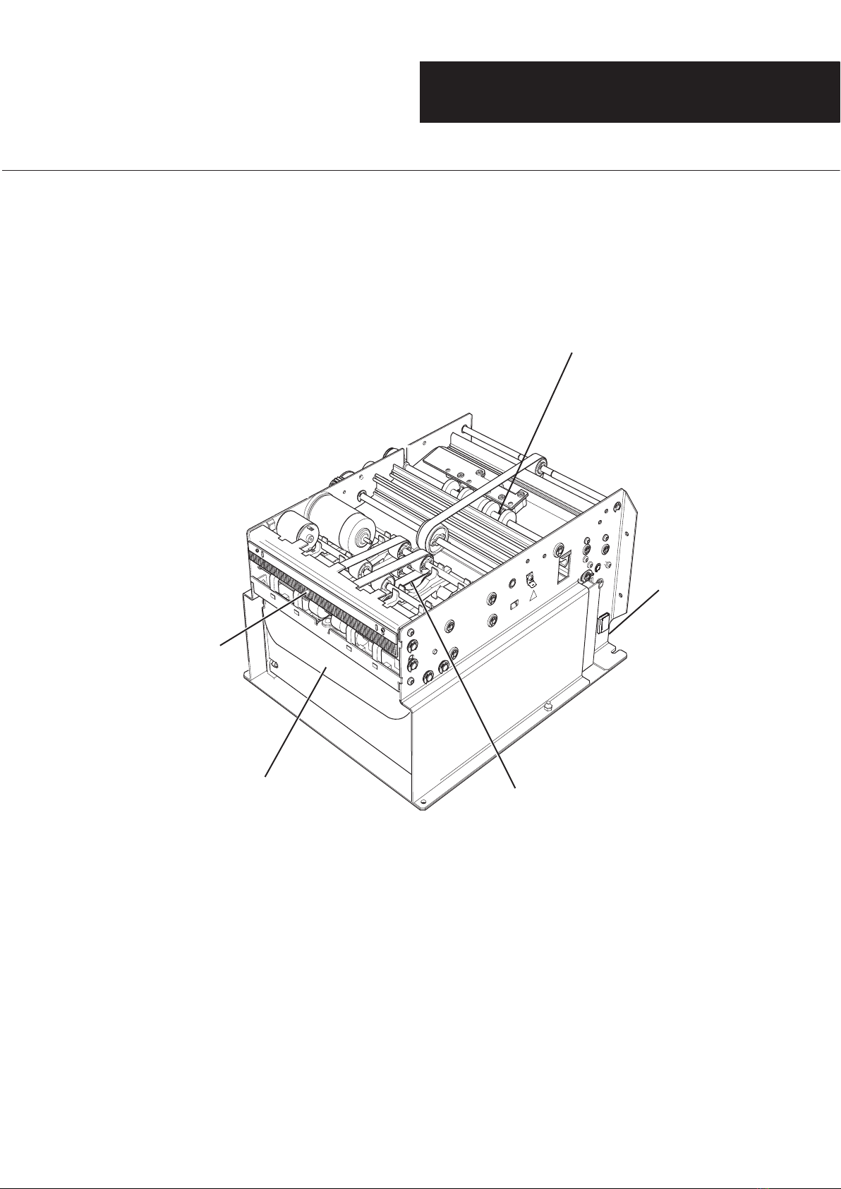
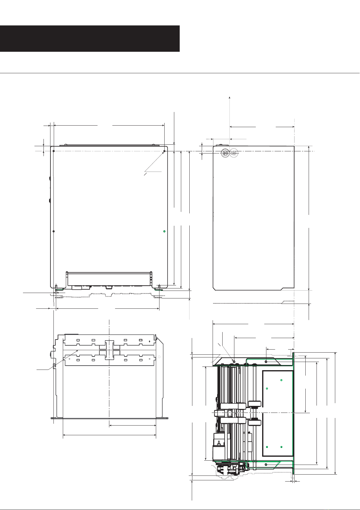
Assembling the MiniMech in a cabinet.
When assembling the MiniMech into a cabinet, we
recommend the use of the two slots and two holes
as shown in diagram to rmly attach the MiniMech
into the cabinet.
Recommendations for transporting, pulling and
lifting MiniMech
The original packaging is designed to ensure
safe travel for the MiniMech. We therefore rec-
ommend that you do not dispose of the pack-
aging as it can be used for future transportation.
When lifting the MiniMech, lift as shown below.
When transporting the MiniMech and not us-
ing the original packaging the Cassette must be
secured with tape as shown below.

7
Power Supply
The MiniMech requirements and recommenda-
tions for an external power supply is as follows:
Input Connector
The AC-mains connector is recommended to be
IEC-320 style.
Output connector
The DC-output connector must consist of an AMP
MTA156 2-pos connector with "locking ramp" or
equivalent.
DC output voltage
+24.0 V, !10%
SELV output and Limited Power Source
Load current, continous
Min - 0.1 A
Max - 2.0 A
Load current, peak
Max 3.0 A, duration 100 ms
Pin assignements
Pin 1 - 0V return
Pin 2 - +24 V
Over voltage protection
The +24 VDC must not exceed 30 volts.
Additional
On request Talaris can supply a power supply, P/N
A008263, to run the MiniMech.
As an option Talaris can supply a std RS 232 com-
munication cable - refer to page 13.
Weight
MiniMech 4.8 kg (with empty NRC 100)
NRC 100 1.35 kg (without notes)
Power Supply 0.4 kg (optional)
Climatic Requirements
Temperature
Operating +5 to +50 °C / +41 to +122 °F
Storage -5 to +60 °C / +23 to +140 °F
Transport -40 to +70 °C / -40 to +158 °F
NOTE!
The transport temperature is valid
for 72 hrs maximum.
Relative Humidity
Operating 10 to 85%
Storage 5 to 95 %
Transport 5 to 95 %
specifications

8
site preparation
MiniMech dimensions
All dimensions in
millimetres (mm)
dimensions
The dotted line indicates area occupied by ca-
bles and screw heads.
Dimension 122.7 is the measurement between
the mounting holes at the front of the MiniMech
and the center of the note.
Note

9
site preparation
Delivery slot dimensions
The most important item when integrating the
MiniMech into a cabinet is that the delivery slot
of the MiniMech is correctly aligned to the slot
in the cabinet.
If the MiniMech is moved out from and into the
cabinet e.g. on slides, the delivery slots must
always be aligned correctly when the MiniMech
is pushed in. This could be achieved by using a
docking device by adjusting the position of the
MiniMech.
Note also the dimensions of the cabinet deliv-
ery slot and the distsance from the reference
point to the bottom surface of the cabinet top
plate.
• If the slot in the cabinet is too narrow, the
notes may jam.
• If the distance between the cabinet and the
MiniMech is too large, the notes may slip
between cabinet and machine and miss the
delivery slot.
• Depending on the wall thickness, the cabinet
delivery slot may have to be chamfered to
give access to the notes.
dimensions

10
Note and Reject Cassette
NRC 010
site preparation
note & reject cassette dimensions

11
site preparation
required space upon service and maintenance
For refilling
For operator maintenance
• The space around the MiniMech is required for
commissioning of the MiniMech
• The space in front of the MiniMech is required
for removing and inserting the note compart-
ment
• The space beside the MiniMech is required for
easy access to the rear of the MiniMech.
• The space in front of the MiniMech is required
for removing and inserting the note compart-
ment
For service and maintenance

12
connections
site preparation
Note!
* Never connect the machine to anything else
then +24 V +-10%.
* The Power Supply( DLRS or the ATM-
ps ) Must be switched off when the power
connector of the MMC is tted.
Power Connector
The power connector is of type AMP MTA 156-2.
Connect PS to machine as shown.
ESD protection
Internal inter module connections and signal con-
nections in modules must not be touched without
measures taken for ESD protection.
Safety Switch Connector
A safety switch connector is located on the Ma-
chine Controller and controls the current to the
motors. It is recommended to connect the safety
switch connector to a switch sensing the cabinet
door position, should the door then be opened the
MiniMech will not be operatable.
PS connector
Safety connector
COM port
GND
+24 V

13
D016128-02
site preparation
Communication connection
The communication connection is according to RS232 C
standard, see description below.
Detailed information regarding communication, see section
6 in the Communication & Command Reference Manual
(CCRM) for MiniMech Doc. No. 8030759
It is recommended that a lter connector is used in the cabi-
net if the communication line is threaded out of the cabinet
holding the dispensing mechanism.
Talaris can offer a std RS-232 communication cable,
P/N A008081, as an option.
If it is prefered to use other communication cables, Talaris
recommends the following:
1 Connector, D-SUB 25, AMP 748 051-1, shielded
2 Connector, D-SUB 9, AMP 748 047-1, shielded
3 Cable, shielded
connections
With handshaking Without handshaking
1
3
2
1
3
2

14
operating the MiniMech
Setup
Start the test program and set the appropriate com-
munication settings in the Set Up tab. Make sure all
settings matches the hardware congurations on the
machine and communications cable.
The image shows the default settings.
Dispensing
To operate the MiniMech, the following commands
are normally needed.
Purge - Starts the main motor and clears the note
path.
Dispense - Dispenses the number of notes typed in
the dispense box - maximum allowed is x notes.
Single Note Dispense - Dispenses 1 note which will
remain in the outlet - must be followed by a Single
Note Eject.
Single Note Eject - Ejects the note that has been
dispensed to the outlet with the Single Note
Dispense command.
Learning Notes
Required before commissioning
The learning notes mode is activated the very rst
time the machine is booted or with software com-
mand WD/392/0.
. Make sure the notes in the note tray are of
adequate quality.
. Make sure the reject compartment tray is empty.
In FW rev.1-3
. Issue a dispense command with one note as an
argument.
In FW rev.4
. Issue Dispense or Test dispense with one note
as an argument.
The machine will now feed six notes. If the com-
mand is issued as a Dispense, ve of them will
be rejected and one note will be dispensed. If
the command was a Test Dispense, all notes will
be rejected.
Verify there are ve notes in the reject compart-
ment and one note dispensed if the command
was a dispense. Verify there are six notes in the
reject compartment and no notes dispensed if
the command was Test Dispense.
If the number of notes rejected and dispensed
are correct according to above, the learning
notes sequence was successful. If not go back
and put the machine in learning notes mode and
perform a new Leaning-notes sequence.
Please refer to CCRM, Doc No 8030759.

15
clearing note table
Clearing NQ data table
Whenever changing denomination it is required to
clear the NQ data table. The NQ data table keeps
information of the denomination previously proc-
essed through the machine, and this has been
achieved through a learning procedure. A learning
procedure is performed when the NQ data table
is empty, and is done by picking 5 notes from the
NRC 010. The NQ reads the size and thickness of
the note and sends the information to the machine
controller where it is stored in the non-volatile
RAM. All 5 notes goe to reject.
Clearing NQ data table with MM Test SW
Start the MM Test SW. Make sure it can commu-
nicate with MM010 by issuing a Purge or another
command that will reply.Type WD/392/0 from the
Cmd Str tab in MM Test, in the Command box and
push the Send button.
It is possible to read out width and thickness
of the denomination learned by the MM010
from FW version 2001.01.01. If the reply is
0000000000000000000, the NQ data table is
empty.
Clearing NQ data table with jumper JP2 on
MC
There are 2 jumpers located on the Machine Con-
troller. JP2 is for clearing the NQ data table as
shown.
Switch off the MM010 and place, or remove, the
jumper on JP2. Switch on the MM010. If the status
of JP2 is changed from closed to open, or vice
versa, the machine will empty the NQ data table.
This means that there is no default position for the
jumper so leaving the jumper in one or another
position will not clear the NQ data table - it is the
status change that clears the NQ data table.
From version 2001-01.01 all 3 LED’s on the Ma-
chine Controller will ash rapidly if there is no infor-
mation in the NQ data table.
NOTE!
JP1 is for enabling the possibility to change com-
munication settings such as baudrate and parity
with a WD items 115 (baudrate) and 116 (parity),
therefore, placing the jumper on JP1 will not harm
the machine, but the NQ data table will not be
cleared and the machine will after power-up oper-
ate with the settings from items 115 and 116, and
it will not be possible to communicate with the
machine with communication settings prior to the
change. With no jumper on JP1 the machine will
operate with default settings baudrate 4800 and
Even parity.
Always remember to check that the NQ data table
is cleared and also perform the learning note pro-
cedure to verify it has been performed success-
fully.

16
NRC 010 settings
Removal of note guides
• Loosen and remove six screws on each side of
the cassett according to the illustration.
• Pull the reject box slightly backwards according
to the illustration.
• Lift out the note guides as shown.
Fitting of note guides
• Ret the note guides according to table on
page17. Use the marked pins as a reference
when retting the guides into the matrix.

17
Note height (mm) Adjustment
From To Position
55 57 1
58 60 2
61 63 3
64 66 4
67 69 5
70 72 6
73 75 7
76 78 8
79 81 9
82 84 10
NRC 010 settings
Note table
Follow the table for note width and note length to
see in which position to t the note guides.
• Push reject box back into place and tighten the
six screws.
Note width (mm) Adjustment
From To Position left Position right
108 111 J J
112 115 J I
116 119 I I
120 123 I H
124 127 H H
128 131 H G
132 135 G G
136 139 G F
140 143 F F
144 147 F E
148 151 E E
152 155 E D
156 159 D D
160 163 D C
164 167 C C
168 171 C B
172 175 B B
176 179 B A
180 183 A A
Tables for adjustment

18
External interconnection
Interconnecting cables and cable assemblies
used for external interconnection between parts of
equipment or between components
Chassis GND
The machine chassis needs to be connected to
GND due to EMC levels. The GND connection can
be made either on one of the six fastening points
on the bottom plate or with a separate cable from
the connector on the sideplate. (See illustration).
Power Supply
External Power Supply must be Limited Power
Source with SELV output.
safety requirements

19

20
The Talaris Commitment
Talaris are World Experts in cash management. Across the globe 2,300 personnel,
with over 130 business partners deliver technology and solutions that provide security,
productivity and innovation to our customers.
The company is committed to the highest ethical standards and compliance
with legislation and to be a fair employer wherever we operate. As a responsible
organisation we maintain a disciplined approach to our corporate governance and
operate to the optimum professional standards in all aspects of our business.
Talaris will always seek to provide a safe and productive work environment where
all employees can grow and be challenged. Wherever we operate our objective is to
contribute actively to the community and the local environment. An intrinsic part of
our business philosophy across our product and service offerings is to be consistently
environmentally responsible and to continue to improve our performance across all
environmental issues wherever possible.
Talaris Cash Dispensing AB
642 84 Flen
Sweden
T +46 (0)157 655 00
F +44 (0)157 151 75
www.talaris.com
This document is for general guidance only. Talaris Limited is pleased to give detailed specications of its products in this document. As the Company’s products and services are continually being developed it is
important for customers to check that the information contained herein includes the latest particulars. Although every precaution has been taken in preparation of this document, the publisher assumes no responsibility
for errors or omissions. Neither is any liability assumed for damages resulting from the use of the information contained herein. This document is not part of a contract or licence save insofar as may be expressly
agreed. All capacities and throughput gures are subject to note size, note quality and process used. All items of technical information, advice, know-how, drawings, specications and other similar items communicated
in this document are condential, and shall not be disclosed to a third party without prior written consent of the publisher. Talaris is a trademark of Talaris Holdings Limited. © Talaris (Sweden) AB 2008.
Other manuals for MiniMech 010
1
Table of contents