Product Name:
General information
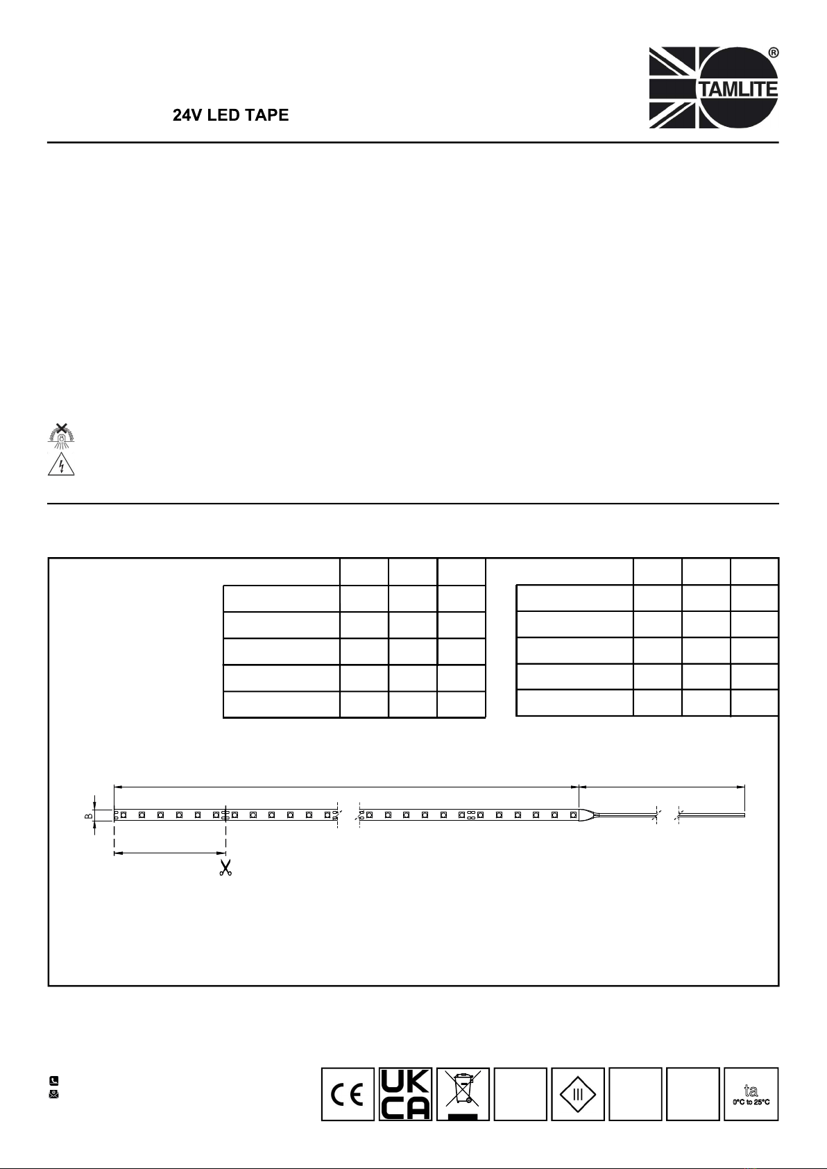
Dimensions
Page 1 of 2
A C
100.00mm
+44(0)1952 292441
Document No: V1
Tamlite Technical
Stafford Park 12,
Telford, Shropshire,
TF3 3BJ
INSTALLATION & OPERATING INSTRUCTIONS
• This luminaire must be installed in accordance with the latest edition of the IET Wiring Regulations and local Building Regulation
by a qualified competent person.
• The mains power supply must be turned off before inspection, installation or removal of the luminaire, ensuring that the supply is
locked off to prevent inadvertently switching the supply on.
• It is the installer’s responsibility to ensure that the installation is suitable for the total load of the luminaire(s). The supply cable
fuses/circuit breakers must be correctly rated for the electrical load and taking into account for any transient inrush currents that
may occur.
• It is the installer’s responsibility to ensure that the environmental operating and storage conditions are complied with and that any
fire risks are considered.
• Do not perform insulation strength or insulation resistance tests on the installation with the luminaire(s) connected, this can
damage the luminaires and give erroneous readings.
• Do not loop-in supply cables at the luminaire supply terminals unless there is provision for 2-way connection at the terminals.
• The light source contained in this luminaire must only be replaced by Tamlite Lighting or an appointed service agent.
• Emergency lighting luminaires must be installed and maintained in accordance with the emergency lighting standard BS 5266-1.
• To ensure that the product warranty remains valid, the luminaire must be installed and maintained in accordance with these
installation instructions and the product must not be modified in any way.
Luminaires marked with this symbol must not be covered with thermally insulating material.
This symbol on covers over light sources indicates dangerous live parts do not operate the luminaire with this cover removed.
IP20 IK03
24V DC ta
0°C to 25°C
B (mm)A (mm)
1000 10
FX241NW / FX241WW
C (mm)
2000
2000 10
FX242NW / FX242WW 2000
3000 10FX243NW / FX243WW 2000
4000 10
FX244NW / FX244WW 2000
5000 10FX245NW / FX245WW 2000
6000 10
FX246NW / FX246WW 2000
7000 10
FX247NW / FX247WW 2000
8000 10
FX248NW / FX248WW 2000
Warning!
This LED tape MUST be connected to a suitable driver.
Please refer to the driver’s instructions.
9000 10
FX249NW / FX249WW
200010000 10
FX2410NW / FX2410WW
2000
B (mm)A (mm) C (mm)


