Tarfire SF-2200H-QG User manual

1
Flame/Plasma CNC Cutting System
SF-2200H-QG
(V2.1)
Operating Manual

Contents
System Functions Overview
System Operating Menu
Auto Function
Edit Function
Command Function
Figures Setting
Graphic Libraries
Diagnose Functions
System Input / Output Interface
Appendix:
1. Exterior Dimension
2. Software Upgrade Instruction

SF-2200H Flame / Plasma CNC Cutting System Operating Manual
1
* Please read carefully this manual before use the system.
Attention:
1) After open the packing case, please check the goods and whether accord with
the list.
2) This manual is only for Portable Flame/Plasma cutting machine system
produced by Beijing Start Microstep.
3) Operating environment temperature is 0-40℃. Relative humidity should be
controlled in 0-85%. Under high-temperature, high-humidity, caustic gas, must
adopt special defend measure.
4) In order to ensure control system working normally and improve system
reliability and ensure the operator’s safety; cutting machine tools and control
system all should be well earthed.
5) Control system should be insulated from outside to avoid dirt and powder
entering and result in control system working abnormally, system parts
damaged, etc.
6) The system operator should be well-trained and familiar with the system
before operating special operator.

SF-2200H Flame / Plasma CNC Cutting System Operating Manual
2
7) The inside power source of CNC system does not allow connecting with other
electric apparatus.
8) Toward some area that power supply is nonstandard (such as zero line and
earth wire sharing or no zero line), in order to ensure control system working
normally and improve system reliability and sure operator’s safety, you must
use isolation transformer that three-phase/two-phase AC380V transfer to two-
phase AC220v between electric network and control system.
9) If problem existed, please contact our company. If don’t familiar with system,
are not allowed to take down system.
10)Output voltage for the control system is suitable only for use of the USB Disk;
and is not supposed to connect with other USB devices to avoid unexpected
damages.
11) Power of the system must be turned off while switching between touchpad
keyboard and exterior keyboard.
12) This operating manual is the property of Beijing Microstep Control
Technology. The final explanation right of this manual belongs to Beijing
Microstep Control Technology.

SF-2200H Flame / Plasma CNC Cutting System Operating Manual
3
Contents
SECTION 1 Overview------------------------------------------------------------------------------------------4
1.1Function--------------------------------------------------------------------------------------------------------4
1.2Features--------------------------------------------------------------------------------------------------------4
1.3Hardware Specifications-------------------------------------------------------------------------------------4
1.4Control panel illustration---------------------------------------------------------------------------------------5
1.5Connecting Instruction-----------------------------------------------------------------------------------------6
SECTION 2 Main Menu-----------------------------------------------------------------------------------------7
SECTION 3 Auto Function-----------------------------------------------------------------------------------8
3.1Auto menu instruction--------------------------------------------------------------------------------------8
3.2Function-------------------------------------------------------------------------------------------------------9
3.3Speed Mode and auto cutting------------------------------------------------------------------------------9
3.4Control and Compensate during Auto cutting-------------------------------------------------------10
3.5Break resume and power down come back---------------------------------------------------------11
3.6Select Segment function---------------------------------------------------------------------------------11
3.7Extend pierce-----------------------------------------------------------------------------------------------12
SECTION 4 Edit------------------------------------------------------------------------------------------------13
SECTION 5 Commanding system---------------------------------------------------------------------------15
5.1Programming symbol-----------------------------------------------------------------------------15
SECTION 6 Parameter Setup------------------------------------------------------------------------------16
6.1Parameters setup---------------------------------------------------------------------------------16
6.2Figure setting--------------------------------------------------------------------------------16
6.3Flame parameters---------------------------------------------------------------------------------18
6.4Plasma parameters--------------------------------------------------------------------------------19
6.5Control parameters--------------------------------------------------------------------------------20
SECTION 7 Diagnoses----------------------------------------------------------------------------------------22
SECTION 8 Library Shapes---------------------------------------------------------------------------------23
8.1Library setting------------------------------------------------------------------------------------------23
8.2Shape selection-----------------------------------------------------------------------------------23
8.3Shape setting and nesting-----------------------------------------------------------------------------------23
APPENDIX 2 Exterior dimension---------------------------------------------------- 25
APPENDIX 2 Software upgrades instruction---------------------------------------------------------------26
APPENDIX 3 G-codes list---------------------------------------------------------------------------------------27
APPENDIX 4 M-codes--------------------------------------------------------------------------------------------28
APPENDIX 5 Error cost list--------------------------------------------------------------------------------------28
APPENDIX 6 Cutting parameters for oxy-propane--------------------------------------------------------29

SF-2200H Flame / Plasma CNC Cutting System Operating Manual
4
Section 1 System Overview
1.1 System Function
SF-2200H-QG Flame/Plasma CNC cutting machine system is a desirable control system suits
the needs of both flame and plasma cutting. The operating display by system adopt windows
hint step by step under main menu, after press one function key, system will display the
sub-menu.
According to the hint and press 【F1】to 【F6】to select. Press ESC to quit and return to back
menu.
1.2System Feature
High-reliability, Prevents system from strong plasma disturbs and lightning strike etc;
32MB storage space, the cutting program can have 10000 lines;
Chinese and English can switch easily, can execute, display and save Chinese file name;
Rich software function, embedded cutting technique, specialty is dealing with little line, it is
used widely in Ad, Iron technique etc;
Can extend to 4 axes synchronized function;
Dynamic shape attach 10.4 LCD display;
Adopt USB disk to Read/Write program to upgrade software.
1.3 Hardware Specifications
1) Industrial grade ARM7 chip;
2) System offers: Input 16 ports, output 14 ports;
3) Synchronization: Two axes, can extend to Four axes;
4) Pulse Equivalence: Electronic gear, numerator and denominator can reach to 1-65535.
5) Max speed: When the Pulse Equivalence is 1μ, max ospeed is 6m/minute;
6) User’s programspace:16-32M;
7) Size: 410*310*119(mm);
8) Work Temperature: 0℃–+40℃Storage Temperature: –40℃-- +60℃

SF-2200H Flame / Plasma CNC Cutting System Operating Manual
5
1.4、System PanelInstruction
Label
KEY
USB
Power
supply
Earth
Interface
Insurance tube
Motor
s
Motor X,
Y
Output
Input
Rear Lock
10.4" LCD
Display
Emergency
Button
Power
Switch
USB
Interface
Programming
and operating
keypad
PC keyboard
interface

SF-2200H Flame / Plasma CNC Cutting System Operating Manual
6
1.5、Connection Instruction
AC220
AC220

SF-2200H Flame / Plasma CNC Cutting System Operating Manual
7
Section 2Main Menu
2.1、MenuFeatures
Menu display applies step-by-step hint style. Under the main menu, system loads all the available
functionsafterenteringthesub-menu.Followthehintsthatwindowsdisplays,press【F1】to【F8】
tochoosedesiredfunctions,pressESCtoabortandreturntoupperlevelmenu.
2.2、MainMenu Function
VersionNumber:Underleftbottomcorner,infoaboutsoftwareversionisdisplayed.
[F1]Auto:Forcuttingoperationsusingastoredprogramorstraightcutting
[F2]Edit:Edit/Change/Savefiles/Loadfiles
[F3]Para:Setormodifycuttingparameters
[F4]Diag:DiagnoseInput/Outputports
[F5]Iib:ShapeLibraryoffersexistingstandardfigures
[G][G][3]Initialize:Ahintisshownasbelow;
图2.1 系统开机菜单界面
图2.2 系统初设对话框
FileFormat------Format the user’s program area;
Parameter-------Initializeoriginalparameters
中文方式-------Select between Chinese and
English。

SF-2200H Flame / Plasma CNC Cutting System Operating Manual
8
Section 3Auto Function
Undermainmenu,press[F1]toenterAutoFunctionmenu,shownasbelow:
3.1、Auto menuinstruction
3.1.1SpeedSetting
1) Afterpressed 【HCuttingSpeed】button,lefttopcornerdisplaysF×(SpeedRatio)= Pre-setcuttingspeed
2) When 【H Cutting Speed】button is not pressed, left top corner displays F×(Speed Ratio)=Manual Cutting
Speed.
3) SPEEDisthecurrentspeed,use 【F+】and 【F -】toadjustspeedratio。
4) Underthisfunctionmenu,press 【F】tomakequickspeedadjustment
5) CAUTION:Speed displayed could be either in inch or millimeter depends on the parameters setting in the
system
Function Options under Auto Cutting
【F1】SECTION: Assign system to cut from any part of the program.
【F2】RESBREK: Find breaking point to resume work.
【F3】MOVE: Manually move one axis each time.
Auto Function Menu
Current Speed
File Name
Strong Current
Output
Hole No.
Strong Current Command
and Compensation
Input output display
Function Menu
Operating
hint
Coordinates
Graphic
Display
Cutting Parameters

SF-2200H Flame / Plasma CNC Cutting System Operating Manual
9
【F4】VIEW: Check whether the graphic program loaded is correct.
【F5】MIRR: Program runs as mirror image, default is non-mirror mode.
【F6】SCALE: Enlarge or reduce the display size of cutting shape.
【F7】ROTATE: Rotate the angle of cutting.
【F8】ASSI: Assist users to perform additional functions.
3.2.1【F8】ASSI
Press 【F8】to enter the next level of control functions。如下图 3.2
1) 【F1】AUTO, press this button to return back to main menu.
2) 【F2】Test Beginning point, related with ROTATE function in upper level control menu
3) 【F3】Test ending point, related with ROTATE function in upper level control menu
4) 【F4】MDI,Currently not applicable, reserved for future uses.
5) 【F5】Set coordinates,set X/Y as any desired number.
6) 【F6】Set compensation, press this to set compensation width, if compensation is not needed,
insert 0
7) 【F7】Return to reference point, enable users to return to original starting point (position of G92 is
commonly (0,0)).
8) 【F8】Turn off each I/O port in order
3.3、Speed Mode(SCALE)and auto cutting ignition
3.3.1 Moving Speed
In no-load moving mod, torch is moving at the maximum moving speed X speed ratio. User should only
adjust to speed ratio to change speed of cutting machine.
3.3.2 Cutting Speed
In cutting mode,actual speed is cutting speed limit X cutting ratio auto ratio adjustment can be
achieved by F+/F- during cutting. Under non-cutting mode, press【H】cutting speed to adjust ratio
by pressing F+/F-.
3.3.3 Backing Speed
Under backing mode, backing speed is cutting speed X backing ratio,Backing ratio can be adjusted
by F+/F-.
Once all three-speed settings are finished, speed properties will be saved automatically, and not
affected by powering off the machine.
图3.2 Accessibility menu

SF-2200H Flame / Plasma CNC Cutting System Operating Manual
10
3.3.4、Auto Mode Ignition
1) Before auto cutting starts
To select proper cutting program, choose the suitable cutting speed ratio. Put torch on the cutting
position(Torch will be lifted up after program initializes(executes M70)) ,after other preparation
works are done, the program may start auto mode execution.
2) Two ways to initialize auto mode:
a) Green 【START】button on control panel;
b) Press exterior “START” button
3.4 Under following operations, torch can be moved in order to change positions.
(1)Pause,( 2)Backing,( 3)Piercing,( 4)Select(5)Find breaking point.
Under above conditions, users could press【↑】【 ↓】【 ←】【 →】directly to change torch position(Current
system speed ratio is manual adjustable)。 After moving to desired position, press【START】button,
display is shown as below.
1)Returntooriginpoint
Suggestion, press 【PIERCE】after pre-heating, thus, system starting cutting from the origin
point.
2)Return topreviouscuttingpoint
Piercefirst,applyingcuttingspeedtoreturntooriginalpoint,keepingcuttingfollowingtheprevioustrack.
3)Pierceundercurrenthole
Pierce first, take present coordinates as “adjusting point”
Leaving cutting mode
When in pause, press 【ESC】to return main menu.
图3.3position adjustment dialogue

SF-2200H Flame / Plasma CNC Cutting System Operating Manual
11
3.5、Break point processing
3.5.1. Break point resume
1) When system is in pause or accidentally power off; system saves current torch position as a break
point. The break point is permanent whether system is turned off or not.
2) Under auto mode, as long as the cutting program does not change, press【F2】select break point
function, then press 【START】button, system resumes working from break point.
3) If the torch position did not change, system would call attention to BRK point after system finds the
break point.
4) If the torch position changed (not on break point), system would display following three options
after system finds break point.
a) Backtooriginal
b) Backtocuttingpoint
c) Pierceatcurrentposition
HINT:Press 【PIERCE】after pre-heating, then system would resume cutting from break point.
Press 【ESC】, system leaves cutting mode.
3.5.2 ATTENTION:
Once the cutting program is changed, BREAK POINT will be eliminated from system cache,
thus the system would not be able to find BREAK POINT and would not resume working.
3.6、SELECTMODE
3.6.1、STARTSELECTMODE
Selecttocutfromanysectionofthecuttingprogramthenpress 【START】,
Press【F1】to choose SELECT function, the system will be shown as below:
图3.5 system pause、finds break point then resumes cutting dialogue
SF-2200H Flame / Plasma CNC Cutting System Operating Manual
12
Meanwhile:use 【↑】【 ↓】to move the curser to choose either SELECT mode to cut
Accordingtothechoice,systemwouldchooseordernumbertoprocess.
3.7、Edge piercing of thick sheet
In auto mode, edge piercing is more suitable for thick sheet.
1) Solution of edge piercing:Move the torch to sheet edge before piercing.
2) Start pre-heating. Press 【START】button after pre-heat ends. Torch moves linear distance at
pre-set speed to the piercing position, resumes cutting.
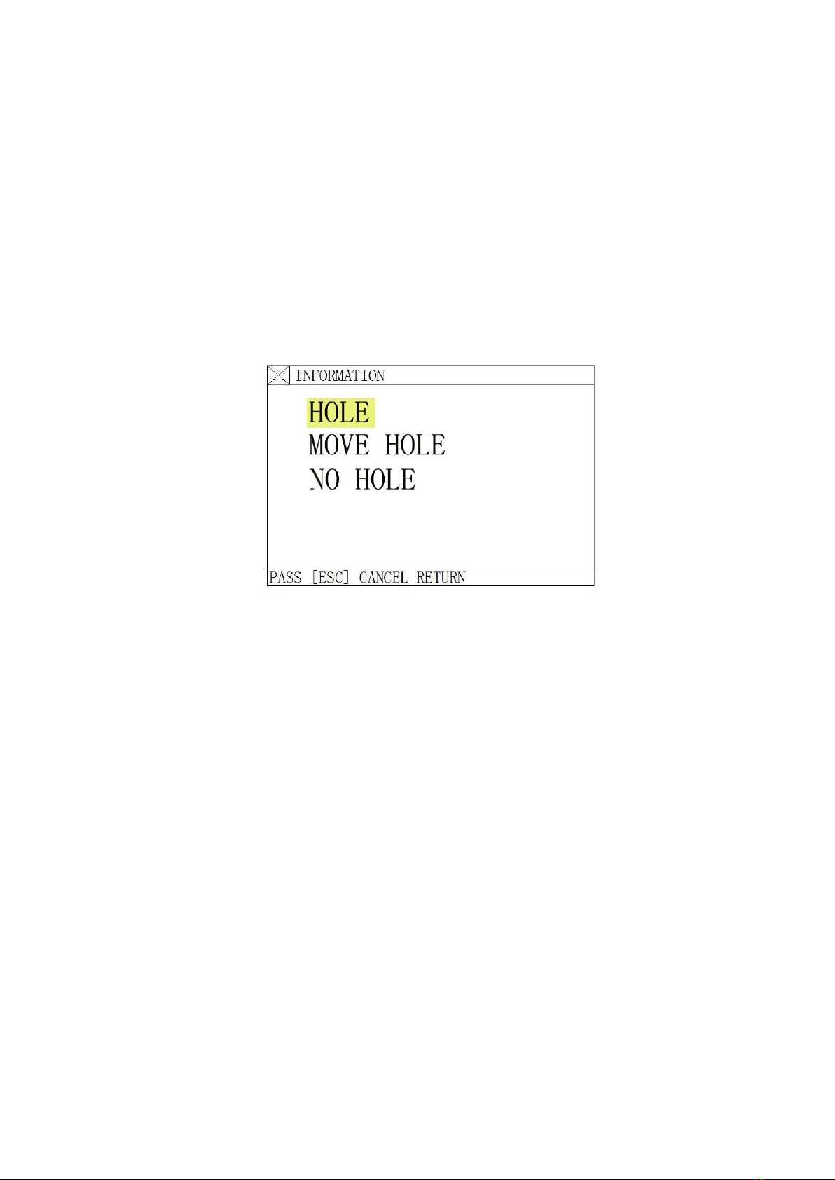
3) In edge piercing, select figure from control menu to set “edge piercing” to 1, means such function is
enacted. Thus every time before piercing, system would display following options.
3.8.1Pierceoncurrentposition
Systemstartspiercing,usuallyoninternalholes.
3.8.2Chooseedgepiercing
1)Userscouldpress【↑】【 ↓】【 ←】【 →】button,move torch to the sheet edge, starts pre-heating.
2)Press 【START】button after pre-heat ends. Torch moves linear distance at pre-set speed
to the piercing position, resumes cutting.
图3.5 selections Menu
图3.7 Option dialogue after choosing edge piercing function

SF-2200H Flame / Plasma CNC Cutting System Operating Manual
13
SECTION 4 Edit Function
4) Under system main menu, press 【F2】to enter Edit mode. System displays the following
picture.
4.1、Edit Mode Menu
4.1.1【F1】New
Create new program, clear out cutting edit area and starting editing a new cutting program.
4.1.2【F2】Load
Load in any existing cutting program into the system, press 【ESC】to give up load function.
4.1.3【F3】SAVE
Saving cutting program, system would pop up a hint. For example:
Choose the file name:1234.TXT
File name should not contain more than 12 letters.
4.1.4、【 F4】Delete file
Choose to delete the program saved to system.
4.1.5、【 F5】Delete lines
Delete entire line under edit mode to increase editing speed.
4.1.6、【 F6】File transfer
Transfer file, this system supports removable disk file transfer, press 【F6】to enter next level menu.
System should be shown as below.
图4.1Edit mode main menu

SF-2200H Flame / Plasma CNC Cutting System Operating Manual
14
【F1】Load program file from removable disk to system;
【F2】Load program file from system to removable disk
4.1.7、【F7】Find Parameters
This function is currently unavailable, saved for future upgrades.
图4.2 Removable disk option menu

SF-2200H Flame / Plasma CNC Cutting System Operating Manual
15
SECTION 5 Commanding System
5.1、Programming symbol
Every action of CNC machine running according to regulate program, every machine program be composed
of some instruction segment, and every instruction segment be composed of some Function word,
each function word must start by letter, parameter follow.
Definition of function word:
N--The No of instruction segment
G--Prepare function
M--Assistant function
S--Main axis function
L--Cycle times or delay time
X--X axis absolute coordinate value
Y--Y axis absolute coordinate value
U--The increment that X axis relative to current position
V--The increment that Y axis relative to current position
I--When cutting arc, the value that the coordinate of the circle centre subtract X axis start value
J--When cutting arc, the value that the coordinate of the circle centre subtract X axis start value
R--Specified arc radius
F--Specified moving speed, used for G01,G02 and G03
Note 1: There are some appointments:
X[U]n -- It can be X or U, n express a value, but only appear once.
Y[V]n -- It can be Y or V, n express a value, but only appear once also.
PPn -- It can be assembled random axis, at least include one axis ,also can include two axis.
Note 2: The instruction execute order is sequence (except transfer and call sub program
instruction); In same
program the M,S and T will be executed before G instruction.

SF-2200H Flame / Plasma CNC Cutting System Operating Manual
16
Section 6 Parameter Setting
Undersystemmainmenu,press 【F3】to enter display interface as below::
6.1、Parameter Setup
Including:
SPED---- Speed parameters, including STARTUP(start speed),TIMING( Adjust time) and HIGH SPD(Max
limit speed);
SYST----System parameters, including NUMERATOR, DENOMINA-(electronic gear
numerator/denominator), MA-ORIGIN(machine tool origin), REFERENCE(reference point),
CLEARANCE, OFFSET, SOFTLIMI+, SOFTLIMI-;
FLAME--- Flame parameters, including IGNITION(ignition time), HOTUP TIME(preheat time), TORCHUP
TIME(torch up time),TORCHDN TIME( torch down time), PIERCEUP(pierce torch up time),
PIERCEDN TIME(pierce torch down time);
PLAS --- Plasma parameters, including torch locate time, Arc on M order, Arc off M order, Arc-feedback,
Locate check, Locate Logic, Pierce time;
CTRL ----Control parameters, including flame/plasma mode select, cutting limit speed, Extend pierce, Shape
Max point etc.
SAVE ----Save function, save the amended parameters.
Attention: Want to make the amended parameters enable, press【F6】to save.
Under PARA menu, input “1928” command, system will hint:
NOTIC: SETUP FACTORY PARAMS
This moment, The amended parameters will be saved to “Factory parameters”, that is When you press
“GG3” and
1) select “PARAMETER”, it will initialize parameters by amended value.
6.2、Figure Setting
图6.1Parameter setting main menu

SF-2200H Flame / Plasma CNC Cutting System Operating Manual
17
6.2.1、Speed Figure
Including:
1.STARTUP——Start speed, the speed that X and Y axis start and stop(unit mm/minute);
2.TIMING—— Adjust time, the time that system from start speed to Max speed needs.
3.HIGH SPD—— The max limit speed, it is the max speed when manual cutting and execute G00
order.
6.2 .2、System Parameter:
Under PARA menu, press 【F2】, displayed as below
1. NUMERATOR/DENOMINA- ---- The ratio that electronic gear numerator and denominator is Pulse
Equivalent*1000. Example: System’s Pulse Equivalent is 0.008mm, the electronic gear
图6.2 速度参数设置
图6.3 System parameter setting

SF-2200H Flame / Plasma CNC Cutting System Operating Manual
18
numerator/denominator
=8/1.
Electronic gear ration formula: N/M= Lead Screw Pitch*1000/(360*Detail Segment/Stepping angle*
Gear Ratio)
2. MA-ORIGIN ----- Machine tool origin, it is a special point that set by approach switch. When the machine
tool don’t set Mechanical Home Position, you can set the Machine tool origin is zero.
3. REFERENCE----- Reference point, Defined as cutting start point, it is specified by G92 order.
4. CLEARANCE ----- Reverse Clearance compensation, as the machine have reverse clearance, when
system move ,want to change direction, this clearance should be compensated. The value should be
measured to get unit:
mm;
5. OFFSET ----Marker Offset. The offset between the marker and torch axis;
6. SOFT LIMI+/SOFT LIMI- --- Soft Positive Limit and Soft Negative Limit, when the program’s coordinates
are over the set value, system will alarm. If don’t use, the parameters set over actual used value
.6.3、Flame cutting parameter
Under para setting, press 【F3】to enter flame cutting parameters, display is shown as below:
1.IGNITION-----Ignition time. Flame cutting, when execute M20, it is the time that open High Voltage Ignite
switch delay; Plasma cutting, it is the time that open Arc Voltage delay;
2.HOTUP TIME----The time pierce preheat(unit: s), when pierce preheat, start preheat time delay, if the
preheat time isn’t enough, press【PAUSE】,The preheat time will be extended to 150s, if preheat finished,
press 【START】, the delay time will be saved to HOTUPTIME parameter automatically;
3. TORCHUP TIME----- Torch up delay time, it is the delay time that execute M70 ,refer 5.4 (unit: s);
图6.4 Flame Parameter Setting
This manual suits for next models
1
Table of contents


