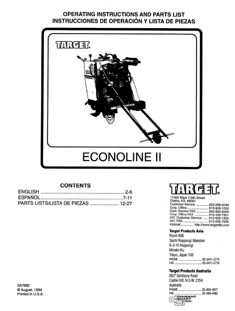
Target FS 1218 EX User manual

OPERATING MANUAL
Electric Fully Automatic Floor Saw
FS 1218 EX
AU DU PONT DE LUTTRE
74
-1190 BRUSSELS –
BELGIUM
PHONE: 322 3
4 83 162
FAX: 322 34 83 136

DRAFT
2

DRAFT
3
Important information before you start!
When the machine is delivered, the wheels are locked in a transportation position and all
electricity is disconnected.
1.
Wheel
lock
The automatic feeding system is active when the
wheel lock (1) is in right position. The wheels are
thereby locked and function as trans security lock.
To employ manual feeding and unlock the wheels,
turn the handle (1) to left position. With the hand
le
turned right, it is impossible to move the machine
without electricity.
2.
Main electricity fuse
The electricity system has a separate main fuse. The
machine cannot be used before the main fuse (2) is
turned into operating position.
Do not operate a
ny electric system before you have
carefully read and carried out the electrically
instructions at page 5 to 8.
3.
Battery and the 12 V main switches
All battery cables are disconnected from the battery
(4) when you receive the machine from the factory.
The 12 V main switch is placed within the saw (3).
The cables have to be connected and the main switch
must be turned on before the winch and the
hydraulic system may be used.
NOTE:
For your own and others security, please employ the mentioned tech
nical
locking systems when
You leave the machine at a construction site,
The machine is stored and
The machine is transported to a new site.

DRAFT
4
1.0
Technical information
FS 1218 EX
This model has an 18.5 kW electric motor and a blade shaft capacity of 950
rpm. The model
is well suited for Diamond blades between Ø 800 mm and Ø 1200 mm.
All Diamant Boart floor saw machines are designed for
using wet cutting Diamond blades.
When ordering Diamond blades, contact your dealer and refer to the technical data
listed
below. Be sure to use correct type of blades. Incorrect blade may cause bad or non
-
cutting
results. Incorrect use may also result in vibration, damaged parts and overheating of the
motor.
Do not use diameter of the blade larger than necessary for t
he actual job situation. We
recommend pre
-
cutting with an Ø 800 mm blade, segments with 5 mm, before using Ø 1000
mm or Ø 1200 mm.
Technical data
FS 1218 EX
Motor output
kW/HP
18.5/25
Electricity
* *
Blade guard
Ø
1200
Cutting depth (maximum)
mm
510
Blade shaft
Rpm
950
Blade flange connection
0/mm
Combi 25,4/60
L x W x FT
cm
160x81x117
Weight
kg 465
*
Different electric systems possible see separate machine card and electric form.

DRAFT
5
2.0
Electrical system
IMPORTANT!
This electric floor saw is available with different electrical systems.
Be absolutely sure that you have ordered and received
the correct system on
your machine. It must correspond with the electrical power supply in your
working area.
Do not connect any electrical power, touch any buttons or operate any of the
electrical systems before you have carefully read and understood all the
instructions covered by this operating manual!
If you have never operated a similar machine before, please carrying out the
test procedures before you start working with the machine.
The electrical data will be found on the machine card and electric
al diagram.
If you have the incorrect electrical system on your machine, take immediate
action, and contact your dealer!
Do not improvise!
Electricity is very dangerous!
ELECTRICAL DIAGRAMS.
This machine is equipped with electrical systems in
accordance with your order
and specifications. Wiring diagrams are separately enclosed with the machine.
Information about voltage, and document numbers for wiring diagram is placed
on the top of the operating panel.
Before use, always make sure that this
information corresponds with the
electrical power supply in the working location.
Whenever new diagrams or other electrical service is required, be sure to
specify the exact information’s on the machine labels as indicated below.

DRAFT
6
3.0 Operating panel
The fully automatically machines are basically operated from the operating panel on top of
the frame.
This manual explains all the buttons, lamp and switches for each technical operation, with
references to the illustration below.
If you have never operated a similar
machine before, or you have moved
to a new working area with new
supplying electricity, it is essential to
carry out the test procedure before
connecting any electricity or operate
any buttons. The test procedure is
explained on the next page.
Explanation of the buttons
1.
Reversing switch.
To choose correct motor running
direction.
2.
Emergency stop. Push down and all
electricity are cut of.
3.
Yellow lamp. Is turned on when
electricity is connected
to the machine.
4.
GREEN
- Start button main motor.
Automatic star/delta start.
5.
RED
- Stop button main motor.
6.
GREEN
-
Lamp. Is turned on when
the main motor are running
7.
RED
-
Lamp. Turns on when main
motor are overloaded.
8.
GREEN
-
Start button feeding motor.
Automati
c star/delta start
9. 9.
RED
-
Stop button feeding motor.
10. GREEN
-
Lamp.
Is turned on when the feeding motor
running
11. RED
-
Lamp.
Turns on when feeding motor are
overloaded.
12. Lowering hydraulic cylinders.
13. Raising hydraulic cylinders.14.
Activating of rear wheel hydraulic
cylinder.
15. Connector.
Input of electricity.
(16. Correct motor running direction.)

DRAFT
7
4.0 Test pro
cedure of the electrical system
Bring the machine to a stable position in a clear area. Any person not involved in the test should
leave the area nearby the machine.
Check before test:
Step 1.
1.
Connect the power supply to the
input plug
(15
) and the yellow
lamp
(3) will turn on to
indicate correct supply of electricity. Be sure to use a safety cable with undamaged plugs.
2.
Check that the emergency stop (2) is pulled over to the operating position.
3.
Turn the
reversing switch
(1) to position 1 th
at indicates that you have chosen an
unknown running direction for the motor. (Wrong direction are not important for this
test)
4.
Push the start button (4) and the main motor start to run in the first step start position.
Wait for 6
-
8 seconds
and the system
turn automatically over to the second and final
start position. The green lamp (6) will now turn on indicating that the motor is working
correct. Look and listen to ensure that everything works perfectly.
5.
Stop the machine by pushing the stop button (5).
S
tep 2.
6.
When the machine has come to a complete stop, turn the reversing switch (1) to position
2 and repeat the start procedure described in item 4 above. The motor running direction
shall now be opposite of test 1.
7.
When the machine runs smoothly, push do
wn the emergency stop (2). All electricity hall
be cut off and the motor will stop.
Final step.
Correct motor running direction (16) is very
important for all further operation of the
If you have problems with this test, please call for professional assistance. Do not try
to open the electric system. Touching the components inside the electric system is
hazardous!
That no blade is mounted
On the blade shaft.
T
hat all covers and guards
are mounted on the
machine.
That the movable frame is
lowered to the ground.

DRAFT
8
5.0
Correct running direction
Never start to work with the machine before you have chosen correct running
d
irection.
The running control procedure has to be carried out when:
-
Electricity has been connected to the machine.
-
The machine has been moved to a new working area with new electrical
power supply.
The motor and blade shaft must always run forward as
arrow (16) illustrated below.
Control procedure including all elements of start and stop, must be carried out
in accordance with the test procedure at page 7, and carried out without any
blade mounting on the blade shaft.
Running direction control:
Ca
rry out the test procedure
step 1
page 7
Observe which way the motor and blade
shaft are running.
If incorrect direction, continue with
step 2.
Never change direction when
the main motor is running.
5.1
Running direction feeding motor
Remark:
The forward feeding motor is connected to the main
electricity. It is essential that correct main running
direction be chosen for the machine.
It is impossible to operate the feeding system, with
wrong motor direction.
The problem often occurs when the mo
tor has been
changed, and the wiring has been connected wrong.
In case see page 21 for service of the feeding system.

DRAFT
9
6.0
12 volt battery system
The fully automatic machines have a 12
-
v system where the battery
and a
safety main switch
are located
inside the frame, and an
Ammeter
located outside upper rear cover.
The battery is fully loaded at delivery. Connect the battery cables to the battery electrodes.
Red to minus and black to plus. Turn the safety switch over to the position
on
and the
12 v systems are ready to be used.
Read instructions for the hydraulic systems and wire winch
carefully before you start to use any of the 12 V automatic systems.
The main switch shall always be turned of during breaks in the work,
transportation or sto
rage.
6.1
Battery charger
The current electric system inside the operating panel has a battery charger
built
-
in.
Whenever electricity is connected to the input plug (15 at page 6) the
charger automatically loads the battery. The Ammeter indicate
s that the
charger is in work.
Note: When there is no reaction at the Ammeter see page 20.
Remember that the battery system is operating the lowering and raising frame,
support wheel and wire winch system. Heavy use can empty the battery faster
than the c
harger is loading the battery. In this case it only takes a short brake for
extra charging of battery.
Long time storage of the machine can also make influence on the battery condition.
An overnight charging can be recommended.
Note: A battery that is da
maged or in bad condition is not indicated
by the ammeter.
For
service
and
troubleshooting
of
the
battery
and
battery
charger:
See
page 20

DRAFT
10
7.0
Support wheel
This machine has an extra support wheel (1) to eliminate manual lifting of the machine w
hen
moving, turning or up lining for correct cutting direction.
The wheel is connected to a hydraulic cylinder operated by three buttons (2) at the top panel.
27
Press button 13 and 14 simultaneously to
lower the support wheel. When it reach
es the
floor the rear part of the machine will be
lifted up. Moving and turning operations
will now go very smoothly.
To replace the machine back to operating
position, press button 12 and 14
simultaneously and the support wheel will be
raised back t
o the upper position.
Always keep this wheel in upper position when not in use to eliminate damage.
This is particularly important at situation as loading, unloading and transport of
the machine.

DRAFT
11
8.0 Automatic feeding system
The machine has
an Electric Hydrostatic feeding system offering you fully adjustable speed
control forward as well as backwards from the 0
-
position.
The electric motor for this feeding system is wired to the main electricity .The
feeding unit is depended on the
choic
e of correct
running direction of the
machine. (see page 8 and 21)
Operating:
Place the operating feeding handle (1) in an
upright
position. This is the non
-
moving position.
Move handle (2) to the
right position
to connect the feeding gear to the rear whe
els.
(Remark that the machine some times needs to be manually moved a little bit forward or
backward to complete this gear connection).
Push the electric start button (4) on the operating panel to activate the Hydrostatic feeding
system.
Stand on the step
-
plate (6) behind the machine to put pressure on the rear wheel.
Push the operating handle (1) forward or backward for movement.
Always deactivate feeding system by pushing the stop button (5) when not in use,
and particularly when leaving the machine.

DRAFT
12
9.0
Automatic lowering and raising blade frame.
On the push buttons (13 and 14) on operating panel you can chose between lowering and raising
movement of the blade frame.
This automation is operated by the hydraulic system that can be adjusted for smo
oth and
controlled feeding of the diamond blade, see page 13.
If you have never operated a similar machine before, please carry out a test before
you start working with this feeding system.
Simply push button 13 for upward
movement,
and button 14
for downwards
These switches are the non-
locking type, and as soon as you release the button, all movement
will stop.
If you have operating problems, see page 9 and 20 for the battery/battery charger or page 22 and
23 for the hydraulic system.

DRAFT
13
10.0
Lowering and raising speed control
In
-
and out feeding speed control of the Diamond Blade is very important.
The fully automatic machines make you able to
adjust individually
the lowering and raising
speed of the blade frame.
Standard settings are n
ormally
slow in
-
feeding speed
, and some
quicker out
-
feeding speed
see
illustration below:
The machine is adjusted to standard setting at delivery. Size of blade and different quality of
concrete or other materials can make it necessary to adjust the fee
ding speed somewhat.
Adjust the speed by turning one or both of the buttons illustrated below.

DRAFT
14
11.0
Tools
The tools are placed in a separate tool holder inside the saw frame:
The C
-
wrench
(1)
is used to open the out flange
(3)
when remo
ving the diamond blade from the blade spindle.
The standard wrench
(2)
is used to lock &e spindle when removing the blade flange. This
wrench fits to a slot on the spindle between the blade and the right side of the movable frame
(4).
Please note
that the slot is situated in the centre of the movable frame on some models.
12.0
Inner blade flange
The blade shaft is designed with an inner blade flange in both ends for mounting Diamond
blades with Ø 25, 4 mm and Ø 60 mm centre holes.
1 I
nner
blade flange
2
Spindel for 0 25,4 mm
centre
hole
3
Distance washer for 0 60 mm centre hole
4
Screws
Diamant Boart delivers the machine adjusted for Ø 60 mm centre hole. If Ø 25,4 mm centre
hole is required, simply remove the distance washer
(
3)
.

DRAFT
15
13.0
Outer blade flanges
The outer blade flanges for mounting the diamond blade to the blade shaft are placed at a flange
holder inside the rear door.
Remark that the right side flange has
left thread
, and the left side flange has
right
thread
, these are respectively marked
L
and
R.
LOCKING
Before mounting the blade be sure, that you have
chosen the blade flange with correct thread.
Place the blade on the blade shaft and fasten the
flange by following the arrows above.
UNLOCKING
Block the blade shaft with the standard wrench and use
the especially C
-
wrench (1) to unlock the outer blade flange.
Observe which side of the blade shaft you are working on to
ensure that you are turning the wrench in correct direction,
shown by the arrows!
Unlocking in wrong direction damage the flange and wrench,
as well as the blade shaft.
-
Never let the blade flange stay mounted on the blade shaft if not engaged in the work.
-
After use, always place the blade flanges back in the flange holder inside t
he frame.
-
Never leave or store the saw with tools or blade flanges mounted to the machine.
-
Always keep the flange systems lean. Damaged parts must be replaced immediately.

DRAFT
16
14.0
12 volt winch system
The 12 V winch system is only to be used for loading,
unloading or moving the machine at very uneven ground
surfaces.
This winch system shall under no circumstances
be used to feed the machine when sawing.
The winch unit (1) is located in front of the basic frame. The wire rope are passing down through
the bottom part and out between the front wheels where the hook (2) is to be found.
SAFETY PRECAUTION
WINCHING -
SPOOLING
MOVING PART HAZARD
To Prevent Serious Injury And Property Damage:
• Do not operate winch before you have read
and u
nderstood the operator’s manual.
• Stand clear of wire rope and bad during
operation.
• Keep others away.
• Always inspect the condition of the winch
and wire rope, before operating winch.
• Do not exceed winch’s rated capacity.
• Never touch wire rop
e or hook while in
tension.
To Prevent Serious Injury:
• Keep hands clear of wire rope, hook and
fairlead opening during operation and when
spooling.
• Always use a rag or cord to hold hook when
spooling under no load.
• Wear heavy leather gloves wh
en handling
wire rope.
• Never winch with less than 5 wraps of wire
rope around drum.

14.1
Pulling out wire rope
– manual
The clutch knob, located on the winch housing
Clutch for free spool
opposite the motor, controls the clutch position.
When th
e clutch is in free spool, the gear train and
wire rope drum are uncoupled, allowing the drum
to rotate freely for pulling out the wire.
To prevent damage, always fully engage or fully
disengage the clutch knob.
WARNING
Do not disengage clutch if
winch
is under load or
wire rope is in tension.
14.2
In and out spooling
–
automatic
The spooling switch is located on the winch motor.
When clutch above is engaged, the gear train is coupled to the wire rope drum, and power may
be transferred from t
he winch motor.
When turning the spooling switch to the right or left the motor activates for automatic in
-
as well
as out spooling.
Operating problems:
Remember that the winch is operated by the 12
-
v battery system. Long
and heavy usage can empty the b
attery faster than the charger is loading
the battery.
More information on battery and battery charger see page 9 and 20.

DRAFT
- 18 -
15.0
Maintenance and inspection
For the safety of yourself and others, always keep the machine in good condition.
Missing and
damaged parts have to be replaced or repaired immediately.
Never do maintenance the machine while the electricity is
connected!
It is very important to clean the machine after use because of the thick layer of concrete that will
be left on th
e machine. This layer will keep for a long time, which in turn will cause a corrosive
attack. The layer may also prevent the machine from working properly.
Cleaning the electric motor is especially important since a layer of concrete reduces the motors
ai
r-
cooling ability, which may cause overheating, overload and failure.
Motor
-
loss of output
The motor has a maximum output limit. In addition to the
output required for the sawing, the total output is used for:
-
Running the motor and the ball be
aring friction,
-
Friction in the V
-
belts, and
-Friction in the shaft bearing.
If the V-
belt and/or shaft bearings are not properly adjusted,
this may cause a significant loss of output left for the
sawing. Therefore, keep these parts in good condition and
change shaft bearings when it shows signs of wear.
Control the V
-
belts
-
In the beginning, V
-
belts must be checked after one day of
use, and if necessary tightened properly.
-
Check the V
-
belts periodically. Loose V
-
belts will cause
wear and tear, and skidding causes loss of output for the
sawing spindle.
-
If one V
-
belt breaks, change all of them. Missing V
-
belts
or uneven V
-belt sets causes loss of output.
-
When changing V
-
belts, make sure that the spindle, pulley
and the motor is adjusted perfec
tly on the centre line. Non
-
parallel V
-
belts cause wear and tear on the new V
-
belts.

DRAFT
- 19 -
16.0
12 V Battery, service and troubleshooting
If the battery is impossible to recharge:
-
Check that the power is correct and connected to the input plug 15 page 6.
-
Check that the battery cables are fully connected to the electrodes.
-
The ammeter shows that the charger is working, but the battery is impossible to recharge?
Check that the battery is not damaged or in bad condition.
-
The Ammeter does not work?
Check
that the fuse inside the charger is OK. See instruction below.
Temperature, unstable use or long storing is discharging the
battery. This influence on the lifetime of the battery, and change to
a new and fresh battery can be necessary.
When change, remar
k that the new battery needs to have the
electrodes (plus and minus) as illustrated
16.1 Charger - problem shooting
The battery charger located inside the main electric panel, have in-
built a
safety fuse (2)
in case
of overload or other electric p
roblems.
When charging and the
Ammeter (3)
do not make any reaction is the problem normally located
at this fuse.
Before you start to check the charger fuse:
Un
-
plug all electricity!!
Remove the top cover for operating panel. The battery charger is l
ocated at left side frame. The
in
-
built fuse has to be found as illustrated below.
Unscrew cap (1) and change the fuse (2) when
necessary.

DRAFT
- 20 -
17.0 Service automatic feeding system
The Electrical Hydrostatic Feeding System is a complete unit based on 3
basic components as
electric motor
(7),
hydrostatic variator
(8) and
gear
(9).
When delivered the speed control is set to a correct limit.
Do not change this!
Service
When delivered the hydrostatic unit (8) is filled with oil,
tested and prepared to be
used directly.
Basically this is a locked system prepared for up to 2000
hours usage before an oil change is required.
It is however recommended to control the oil level
through the inspection glass (10), and refill if necessary.
The oil input (11) is loc
ated outside frame (12).
Change of oil: Remove cap (11). Open drain plug (13) to
pour out
the old oil. Refill new oil as recommended below.
Recommended grade of oil: Esso INVAROL EP 46; 0,5 L
17.1
Trouble shooting
Forward feeding do not work?
1. Did you connect the gear connection? (Item 2 page 11)
2. Did you start the feeding motor? (Item 4, page 11)
3. Did you choose correct motor running direction? (Item
16, page 8)
4. Check that main fuse is turned on. (Page 9)
5.Check that the chain betwee
n gear and rear wheel is
undamaged.
If further problem, call for assistance and refer to the information on the technical plate for motor
as well as the variator shown at the illustration to the left.
Table of contents
Other Target Saw manuals

Target
Target PRO 35 III DIESEL User manual

Target
Target econoline II Use and care manual

Target
Target Quickie 45/12 User manual

Target
Target ES 1400 Use and care manual

Target
Target TILEMATIC TA10100 Use and care manual

Target
Target MINI CON II User manual

Target
Target MICROCON MCC 75E Use and care manual

Target
Target SUPER 60 Use and care manual

Target
Target Port-A-Saw Use and care manual

Target
Target MC18 Use and care manual