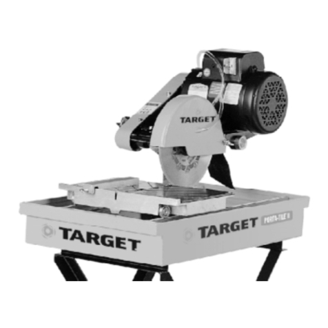
Target Port-A-Saw Use and care manual

1
0A7738
Copyright © November, 2000 DBInc.
Printe in U.S.A.
MODEL: Port-A-Saw
Masonry / Refractory Saw
Electric & Gasoline Models
OPERATING INSTRUCTIONS AND PARTS LIST
INSTRUCCIONES DE OPERACIÓN Y LISTA DE PIEZAS
17400 West 119th Street
Olathe, Kansas 66061
Customer Service ............ 800-288-5040
Corp. Office ...................... 913-928-1000
Cust. Service FAX ............ 800-825-0028
Corp. Office FAX .............. 913-438-7951
I tl. FAX ........................... 913-438-7938
I ter et ........... http://www.targetdbi.com
Target Products Japan
Room 806
Taichi Roppongi Mansion
6-3-15 Roppongi
Minato-ku,Tokyo
Japan 106
Pho e ................................ 03-5411-2775
FAX .................................... 03-5411-2776
Diamant Boart/Target Australia
26/7 Salisbury Roa
Castle Hill, N.S.W. 2154
Australia
PHONE ............................... 02-96344677
FAX ..................................... 02-96804982

2
EVERY MACHI E IS THOROUGHLY TESTED BEFORE LEAVI G THE FACTORY. EACH MACHI E IS SUP-
PLIED WITH A COPY OF THIS MA UAL. OPERATORS OF THIS EQUIPME T MUST READ A D BE FAMIL-
IAR WITH THE SAFETY WAR I GS. FAILURE TO OBEY WAR I GS MAY RESULT I I JURY OR DEATH.
FOLLOW I STRUCTIO S STRICTLY TO E SURE LO G SERVICE I ORMAL OPERATIO .
CONTENTS
Symbol Definitions ............................................................................................................................................ 3 - 6
Hearing Hazard Warnings ................................................................................................................................ 6
Decal Descriptions and Locations .................................................................................................................... 7
Specifications & Po er Sources ....................................................................................................................... 8
Sa Dimensions ............................................................................................................................................... 9
Safety Warnings - Do's and Do Not's ............................................................................................................... 10 - 11
Reference Figures: 1 - 12 ................................................................................................................................. 12 - 14
Pre Operation Checklist .................................................................................................................................... 15
Instructions:
1-Features ..................................................................................................................... ............... 16
2-Assembly .................................................................................................................................. 16 - 17
3-Check Before Operating ........................................................................................................... 17 - 18
4-Fitting the Blade ........................................................................................................................ 18
5-Operating Instructions ............................................................................................................... 18 - 19
6-Incidents During Operation ....................................................................................................... 20
7-Maintenance .................................................................................................................. ........... 20 - 21
8-V-Belt Tension ........................................................................................................................... 21
9-Important Advice ....................................................................................................................... 21 - 22
10 - Accessories................................................................................................................. .............. 22
11 -Repairs ..................................................................................................................... ................. 22
12 - Spare Parts ................................................................................................................. .............. 22
Diagrams and Spare Parts ................................................................................................................................ 40 - 47
Wiring Diagrams ................................................................................................................ ............................... 48 - 49
A TES DE COME ZAR: Lea y compren a to as las a vertencias e instrucciones antes e operar la máquina
que se escribe en este manual. ¡LAS ADVERTE CIAS Y PRECAUCIO ES DE ESTE MA UAL DEBE SER
COMPRE DIDAS Y CUMPLIDAS! SI O SE OBEDECE LAS ADVERTE CIAS, SE PUEDE PRODUCIR
SERIAS LESIO ES O LA MUERTE. ES SU RESPO SABILIDAD el asegurarse que las personas que usen
esta máquina hayan leí o este manual.
CONTENIDO
Definición de Símbolos ..................................................................................................................................... 3 - 6
Advertencias Auditivas de Peligro .................................................................................................................... 6
Calcomanís - Descripciones y Ubicaciones ..................................................................................................... 7
Especificiones y Fuentes de Energía ............................................................................................................... 24
Dimensiones de la Sierra.................................................................................................................................. 25
Advertencias de Seguridad - Los SI y Los NO ................................................................................................. 26 - 27
Ilustraciones de Referencia: 1 - 12 .................................................................................................................. 28 - 30
Pre-Operation Checklist .................................................................................................................................... 31
Instrucciones:
1-Usos ......................................................................................................................... ................. 32
2-Armado ....................................................................................................................... .............. 32 - 33
3-Verifique Antes De Operar ........................................................................................................ 34
4-Colocación De La Hoja ............................................................................................................. 34 - 35
5-Instrucciones De Operación ..................................................................................................... 35 - 36
6-IIncidentes Durante La Operación ............................................................................................ 36 - 37
7-Mantenimiento .......................................................................................................................... 37 - 38
8-Tensión De La Cinta En V ......................................................................................................... 38
9-Consejo Importante................................................................................................................... 38 - 39
10 - Accesorios ................................................................................................................................ 39
11 -Reparaciones ............................................................................................................................ 39
12 - Piezas De Repuesto ................................................................................................................. 39
Diagramas y Lista de Piezas ............................................................................................................................ 40 - 47
Diagramas de Cableado ................................................................................................................................... 48 - 49

3
SYMBOL DEFINITIONS
DEFINICIÓN DE SIMBOLOS
Please rea the instructions for use prior to operating the machine for the first time.
Antes e la puesta en marcha, lea eteni amente las instrucciones y familiaricese con la máquina.
Man atory
Obligatorio
Inication
Inicación
Prohibition
Prohibición
Warning Triangle
Triángwulo De A vertencia
Wear Eye Protection
Usar Gafas De Protección
Wear Hea Protection
Usar Casco De Protección
Wear Breathing Protection
Usar Máscara De Protección
The Use Of Ear Protection Is Man atory
Es Obligatorio El Uso De Protección Au itiva
Wear a Har Hat
Usar Casco Duro
Wear Safety Shoes
Usar Zapatos De Seguri a
Wear Appropriate Clothing
Usar Ropa A ecua a
Remove The Bla e Prior To Hoisting, Loa ing, Unloa ing An Transporting The Machine On Jobsite.
Desmontar El Disco Antes De Desplazar, Cargar, Descargar O Transportar La Máquina En La Obra.

4
Motor Off
Parar El Motor
Use In Well Ventilate Area
Usar En Una Área Bien Ventila a
Do Not Use In Flammable Areas
No Usar In Áreas Inflamables
Machinery Hazar , Keep Han s An Feet Clear.
Máquina Peligrosa - Mantenga Manos Y Pies Aleja os De La Máquina
Danger, Poison Exhaust Gas
Peligro, Gases De Escape Tóxicos
No Non-working Personnel In Area
Prohibi o Para Personas Ajenas A La Obra
No Smoking
No Fumar
Do Not Operate Without All Guar s In Place
No Operar Sin To as Las Protecciones In Su Sitio
Always Keep the Bla e Guar s In Place
Mantenga Siempre Las Protecciones De La Hoja En Su Sitio
Water Supply On
Suministro De Agua Conecta o
Water Supply Off
Suministro De Agua Desconecta o
Water Supply
Suministro De Agua
Keep Work Area Clean/Well Lit, Remove All Safety Hazar s
Mantenga Limpio El Sitio De Trabajo/Bien Ilumina o, Elimine To os Los Riesgos De Seguri a

5
Dangerously High Noise Level
Nivel De Rui o Eleva amente Peligroso
Pay Extreme Attention To The Care An Protection Of The Machine Before Starting Up
Ponga Extrema Atención Al Cui a o Y Preparación De La Máquina Antes De Ponerla En Marcha
Remove Tools From Area an Machine
Elimine Las Herramientas Del Área Y De La Máquina
Oil Pressure
Presión De Aceite
Oil Require
Necesita Aceite
Dipstick, Maintain Proper Oil Level
Varilla De Control, Mantenga El Nivel De Aceite Correcto
Lubrication Point
Punto De Lubrication
Unlea e Fuel Only
Solamente Combustible Sin Plomo
Repairs Are To Be Done By An Authorize Dealer Only
Las Reparaciones Deben Ser Efectua as Únicamente Por Un Distribui or Autoriza o
Diamon Bla e
Sierra Diamanta a
Blae Diameter
Diámetro De La Hoja
Pulley Diameter
Diámetro De La Correa

6
Number of Revolutions Per Minute, Rotational Spee
N° De Revoluciones Por Minuto, Veloci a De Rotación
Bla e Flange Diameter
Diámetro De La Bri a De La Hoja
Machine Mass (lbs)
Masa De La Máquina (lbs)
Engine
Motor
Engine Spee Revolutions/Minute
Veloci a Del Motor En Revoluciones Por Minuto (RPM)
Engine Start
Arranque Del Motor
Electric Motor
Motor Electrica
WARNING
HEARI G HAZARD
DURING NORMAL USE OF THIS MACHINE, OPERATOR MAY BE EXPOSED TO A NOISE
LEVEL EQUAL OR SUPERIOR TO 85 dB (A)
ATENCION
RIESGO DE DAÑO AUDITIVO
EN CONDICIONES NORMALES DE UTILIZACIÓN, EL OPERADOR DE ESTA MÁQUINA PUEDE
ESTAR EXPUESTO A UN NIVEL DE RUIDO IGUAL O SUPERIOR A 85 dB (A)

7
P/N 177588
Location: Blade Guard
(Qty. 1) All Models
P/N 3 5 6
Location: Water Pan Sides
(Qty. 2) All Models
P/N 169 65
Location: Muffler
(Qty. 1) Gas Models
P/N 46326
Location: Motor
(Qty. 1) Electric Models
P/N 46327
Location: Motor
(Qty. 1) Electric Models
DECAL DESCRIPTIO S A D LOCATIO S
DESCRIPCIÓ DE CALCAMO IAS Y UBICACIO ES
P/N 3 898
Location: Blade Guard
(Qty. 1) All Models
P/N 5213
Location: Water Pan
(Qty. 2) All Models

8
Port-A-Saw Specifications
MODEL NO. PS1411 PS1421 PS1431 PS1455
TYPE 1-1/2 HP Electric 2 HP Electric 3 HP Electric 5.5 HP Gasoline
Item No.
(with Water Pump) M5405120S M5406120S M5407120S M50109
Blade Guard Capacity: 10 - 14" 10 - 14" 10 - 14" 14" Only
(250 - 350 mm) (250 - 350 mm) (250 - 350 mm) (350 MM)
Blade Sha t RPM: 2509 2509 2509 2950
Max. Depth O Cut: 5.0" (127 mm)
Blade Arbor Size: 1.00" (25.4 mm)
Blade Sha t: Seale Ball Bearings
Blade Sha t Drive: Two 4L370 V-Belts Two 4L370 V-Belts Two 4L370 V-Belts 3VX V-Belt (2 Ban )
Blade Guard: One Piece Steel, Sta-LevelTM Design, 14" (350 mm) Maximum Capacity
Blade Coolant: Water
Water Pan: 3.86 x 17.73 x 30.73 Inch (98 x 450 x 780.5 mm), 6.75 Gallon (25 Liter) Capacity (At 3" Depth)
Conveyor Cart: Cast Aluminum w/ Vulcanize Rubber Top, A justable Measuring Rule, 45° / 90° Cutting Gui e
Water Pump:
Electric Models:300 Gallons / Hour, Submersible, Totally Epoxy Seale , Thermal Over Loa Protecte
Gasoline Model: 8 GPM, Belt Drive, Soli Bronze, With Strainer & Built-In Priming Pump with Check Valve
Frame: Heavy uty, Jig Wel e X Brace Steel, Open Throat Design For Unlimite Ripping
Weight: Pounds (kg):
Saw Crated: 171 (77.7) 182 (82.7) 192 (87.3) 209 (95.0)
Saw Uncrated: 160 (72.7) 169 (76.8) 181 (82.3) 198 (90.0)
Saw Operating
(Water In Pan): 221 (100.5) 230 (104.5) 242 (110.0) 259 (117.7)
olding Stand
(Unboxed): 24 (10.9) 24 (10.9) 24 (10.9) 24 (10.9)
oot Pedal Kit
(Boxed):14 (6.4) 14 (6.4) 14 (6.4) 14 (6.4)
Electric Cord: 0.40 (.18 ) N / A N / A N / A
MODEL NO. PS1411 PS1421 PS1431 PS1455
TYPE Electric Electric Electric Gasoline
Engine / Motor: Bal or Bal or Bal or Hon a
Horsepower (kw): 1-1/2 (1.1) 2 (1.5) 3 (2.2) 5.5 (4.0)
RPM: 3450 3450 3450 3500
Speci ications:T.E.F.C T.E.F.C T.E.F.C
Voltage: 115 / 208-230 115 / 208-230 208-230
Cycle (Hz) / Current
/ Phase: 60 / A.C. / 1 60 * / A.C. / 1 60 * / A.C. / 1 **
Displacement: 9.9 cu. Inch (163 cc)
Bore: 2.7 inch (68 mm)
Stroke: 1.8 inch (45 mm)
Cylinders / Cycle: 1 / 4
Fuel Capacity: .95 Gallon (3.6 liter)
Oil Capacity: .63 Quart (.6 liter)
Air Filter: Dry Type
Dual Element
with Precleaner
Starter: Capacitor Capacitor Capacitor Recoil
Coolant: Air Air Air Air
* 50 cycle motors available upon special request: 2 HP mo el is 240 Volt, 3 HP mo el is 220-380 Volt
** 3 phase motor available upon special request - specify 230 or 460 volts for factory wiring.
ote: For item numbers on motors / engine see parts list section of this ocument.
Specifications are subject to change without notice.
Power Source

9
Saw Dimensions
ELECTRIC MODEL
FIGURE A
SAW DIMENSIONS
ELECTRIC MODELS (Figure A) GASOLI E MODEL (Figure B)
Item Length (cm) Description Item Length (cm) Description
A38.2" (97.0) Saw Length (Maximum) A43.6" (110.7) Saw Length (Maximum)
B19.4" (49.3) Saw Wi th (Maximum) B22.7" (57.7) Saw Wi th (Maximum)
C28.2" (716.3) Saw Height (Minimum) C34.8" (88.4) Saw Height (Minimum)
D26.1" (66.3) Stan Height (Optional) D26.1" (66.3) Stan Height (Optional)
E56.4" (143.3) Saw Height (Maximum) E63.0" (160.0) Saw Height (Maximum)
F3.8 - 15.1" Bla e Shaft Height F6.4 - 15.0" Bla e Shaft Height
(9.6 - 38.4) (Minimum - Maximum) (16.2 - 38.2) (Minimum - Maximum)
G10.0" (25.4) Cart Length G10.0" (25.4) Cart Length
H18.7" (47.5) Cart Wi th H18.3" (47.5) Cart Wi th
I18.5" (47.0) Cart Travel I18.3" (46.5) Cart Travel
J33.0" (76.2) Saw Base Length J33.0" (76.2) Saw Base Length
K18.0" (45.7) Pan Wi th K18.0" (45.7) Pan Wi th
L33.7" (85.6) Stan To Cart Top L33.7" (85.6) Stan To Cart Top
M35.8" ( 90.9) Ski To Cart Top M35.8" ( 90.9) Ski To Cart Top
7.6" (19.3) Base To Cart Top 7.6" (19.3) Base To Cart Top
O2.1" (5.3) Ski Height (Optional) O2.1" (5.3) Ski Height (Optional)
P11.5" (29.2) Cart - LH Si e P6.5" (16.5) Cart - LH Si e
Q6.5" (16.5) Cart - RH Si e Q11.5" (29.2) Cart - RH Si e
R4.0" (10.16) Flange Diameter R4.0" (10.16) Flange Diameter
S32.0" (81.3) Ski Wi th (Optional) S32.0" (81.3) Ski Wi th (Optional)
GASOLINE MODEL
FIGURE B

10
SAFETY FIRST!
WARNINGS
DOs A D DO OTs
WAR I G: FAILURE TO COMPLY WITH THESE WARNINGS AND OPERATING
INSTRUCTIONS COULD RESULT IN DEATH OR SERIOUS BODILY INJURY.
DO
DO rea this entire operators manual before operating this machine. Un erstan all warnings, instructions, an controls.
DO keep all guar s in place an in goo con ition.
DO wear safety approve hearing, eye, hea an respiratory protection.
DO rea an un erstan all warnings an instructions on the machine.
DO rea an un erstan the symbol efinitions containe in this manual.
DO keep all parts of your bo y away from the bla e an all other moving parts.
DO know how to stop the machine quickly in case of emergency.
DO shut off the engine an allow it to cool before refueling.
DO inspect the bla e, flanges an shafts for amage before installing the bla e.
DO use only reinforce abrasive bla es or steel center iamon bla es manufacture for use on masonry saws.
DO use only bla es marke with a maximum operating spee greater than the bla e shaft spee . Verify spee by check-
ing bla e shaft rpm an pulley iameters an bla e flange iameters.
DO verify saw rive configuration by checking bla e shaft RPM, pulley iameters, an bla e flange iameter.
DO rea all safety materials an instructions that accompany any bla e use with this machine.
DO inspect each bla e carefully before using it. If there are any signs of amage or unusual wear, DO OT USE THE
BLADE.
DO mount the bla e soli ly an firmly. Wrench tighten the arbor nut.
DO make sure the bla e an flanges are clean an free of irt an ebris before mounting the bla e on the saw.
DO use ry cutting iamon bla es with a 1" ( iameter arbor only). Never use amage or worn bla e flanges.
DO use the correct bla e for the type of work being one. Check with bla e manufacturer if you o not know if bla e is
correct.
DO operate this machine only in well ventilate areas.
DO instruct bystan ers on where to stan while the machine is in operation.
DO establish a training program for all operators of this machine.
DO clear the work area of unnecessary people. Never allow anyone to stan in front of or behin the bla e while the
engine is running.
DO make sure the bla e is not contacting anything before starting the engine.
DO always tie own the machine when transporting.
DO use caution an follow instructions when setting up or transporting the machine.
DO have all service performe by competent service personnel.
DO verify the bla e arbor hole matches the machine spin le before mounting the bla e.
DO make sure the gas caps of the machine an the fuel can are properly tightene before starting the engine. Move fuel
can at least 10 feet from machine after fueling.
DO clean the machine after each ays use.
DO remove a justing keys an wrenches from tool before turning it on.
DO keep the han les ry, clean an free of oil an irt.
DO carefully maintain an clean for better an safer performance. Follow instructions for changing accessories. Inspect
tool cor s perio ically an , if amage , have repaire by authorize service facility.
DO use the proper bla e flange size for each bla e size. Never use amage or worn bla e flanges.
DO use caution when han ling fuel.
DO only cut in a straight line.
DO make sure electric powered machines are plugged into a properly grounded circuit.
DO make sure power cords are the proper size and in good condition.
DO follow all electrical codes in your area.
DO use correct voltage and proper extension cords. ever carry tool by cord or yank it to disconnect it from
recepticle. Keep cord away from heat, oil and sharp edges.
DO disconnect tools from power source when not in use, before servicing and, when changing accessories.
DO carefully maintain and clean for better and safer performance. Follow instructions for changing accessories.
Inspect tool cards periodically and, if damaged, have repaired by authorized service facility.
DO always give a copy of this manual to the equipment user. If you nee extra copies, call TOLL FREE 1-800-288-5040.

11
SAFETY FIRST!
WARNINGS
DOs A D DO OTs
WAR I G: FAILURE TO COMPLY WITH THESE WARNINGS AND OPERATING
INSTRUCTIONS COULD RESULT IN DEATH OR SERIOUS BODILY INJURY.
DO NOT
*****************
This saw was designed for certain applications only. DO OT modify this saw or use for any application other than
for which is it was designed. If you have any questions relative to its application, DO OT use the saw until you have
written Diamant Boart, Inc. and we have advised you.
Diamant Boart, Inc.
17400 West 119th Street
Olathe, Kansas 66061
In USA 1-800-288-5040
DO OT operate this machine unless you have rea an un erstoo this operators manual.
DO OT operate this machine without the bla e guar , or other protective guar s in place.
DO OT leave this machine unatten e while the engine is running.
DO OT work on this machine while the engine is running.
DO OT operate this machine when you are tire or fatigue .
DO OT use a wet bla e without a equate water supply to the bla e.
DO OT excee maximum bla e spee shown for each bla e size. Excessive spee coul result in bla e breakage.
DO OT operate the machine if you are uncertain of how to run the machine.
DO OT use amage equipment or bla es.
DO OT touch or try to stop a moving bla e with your han .
DO OT cock, jam, we ge or twist the bla e in a cut.
DO OT transport a cutting machine with the bla e mounte on the machine.
DO OT use a bla e that has been roppe or amage .
DO OT use carbi e tippe bla es.
DO NOT lay power cor s in or near water.
DO NOT replace the motor with any motor that oes not have a special groun ing connection.
DO OT use segmente iamon bla es without water unless specifically esigne for ry cutting.
DO OT touch a ry cutting iamon bla e imme iately after use. These bla es require several minutes to cool after
each cut.
DO OT use amage or worn bla e flanges.
DO OT allow other persons to be near the machine when starting, refueling, or when the machine is in operation.
DO OT operate this machine in an enclose area unless it is properly vente .
DO OT operate this machine in the vicinity of anything that is flammable. Sparks coul cause a fire or an explosion.
DO OT allow bla e exposure from the guar to be more than 180 egrees.
DO OT operate this machine with the belt guar or bla e guar remove .
DO OT operate this machine unless you are specifically traine to o so.
DO OT use a bla e that has been over heate (Core has a bluish color).
DO OT jam material into the bla e.
DO OT grin on the si e of the bla e.
DO OT start cutting with a saw until you have a clear work area an secure footing.
DO OT operate this machine while un er the influence of rugs or alcohol.

12
FIGURES

13
FIGURES
EE
U
RR
DD
GG
C
A1
B2
KK
JJ
T
CC
DD
BB
VV
Y
T
RR Z
TT
X
KK
UU
GG
C
DD
B2
KK
KK

14
Parts Identification:
A. Pan Wel ment
B. Hea Platform Assembly
C. Conveyor Cart Assembly
D. Fol ing Stan (Optional)
E. Ski Kit (Optional)
F. Foot Pe al Kit (Optional)
G. Bearing Clamps
H. Bearings
I.
J. Pivot Blocks
K. Knobs (or Capscrews)
L. Counterbalance Arm
M. Capscrew
N. Lower Bracket
O.
P. Lock Han le
Q. Spring
R. Eyebolt
S. Strainer (Gasoline Mo el)
T. Water Valve
U. Water Pump
V. Primer Bulb (Gasoline Mo el)
W. Isolator (Gasoline Mo el)
X. Wheel (Bla e Guar Pivot)
Y. Setscrew (Bla e Guar Pivot)
Z. Track Bar
AA. Engine Base
BB. Capscrew (Bla e Shaft)
CC. Outer Flange
DD. Diamon Bla e
EE. Water Pump Belt (Gasoline Mo el)
FF.Upper Spring Support
GG. Square
HH. Shims (Not Shown In Figures)
II.
JJ. Capscrews (Bla e Shaft Housing- Rear)
KK. Capscrews (Bla e Shaft Housing- Top)
LL. Wrench
MM. Splash Curtain
NN. Electrical Cor (Water Pump)
OO. Electrical Plug (Electrical Mo els)
PP. Reset Button (Electric Mo els)
QQ.
RR. Power Switch (Electric Mo els)
SS. Belt Tensioning Bolt
TT. Serial Number Plate
UU. Han Grip
VV. Engine Stop Switch (Gasoline Mo el)
WW. Oil Drain Hose

15
PRE OPERATION CHECKLIST
Before leaving our factory, every machine is thoroughly tested. Follow our instructions strictly and
your machine will give you long service in normal operating conditions.
Before starting up the machine, make sure you read this entire Operations Manual and are familiar
with the operation of the machine.
WITH MACHI E COLD A D SETTI G LEVEL:
1. Gasoline Mo els: Check engine oil. Fill to the full mark on ip stick with 10W30 oil, class MS, SD, SE or better.
2. Electric Mo els: Verify all electrical connections are intact.
1 - 2 HOUR OPERATIO CHECK LIST:
ALWAYS place the machine on a level surface with the engine/motor OFF", the ignition switch set in
the OFF position and disconnected from the power source before performing any maintenance. Let
the machine cool down!!
1. Check the engine air cleaner hose clamps. Tighten as require .
2. Tension the bla e rive V-belts. DO NOT over tension!!
SCHEDULED MAINTENANCE QUICK REFERENCE:
Before performing any maintenance, ALWAYS place the machine on a level surface with the
engine/motor OFF and the ignition switch set in the OFF position.
SERVICE DAILY:
1. Check engine oil level.
2. Check bla e guar for amage.
3. Check hoses an clamps for amage
or looseness. Tighten or replace as necessary.
4. Check air cleaner. Clean or replace as require .
5. Clean the reservoir pan frequently.
6. At the en of each ay, flush clean water through the
water pump an hoses
SERVICE EVERY 50 HOURS:
1. Replace engine oil an filter.
2. Clean engine air fins.
3. Check bla e rive V-belt tension.
DO NOT over tension!!!
4. Clean engine fuel bowl.

16
1 Features
2 Asse bly
The operator must
wear protective clothing
appropriate to the work he is
doing.
Any persons not involved in the work should
leave the area.
Use only blades marked with a maximum
operating speed greater than the blade shaft
speed.
Use: Wet or Dry sawing of masonry an refractory.
Tools: Diamon bla es ry or water coole ,
Ø: 10" (250 mm), 12" (300 mm), an
14" (350 mm), with Arbor Ø 1" (25.4 mm).
( or information contact your Dealer)
Depth of Cut (Maximum):
5.00" (127 mm) with Ø 14" (350 mm) bla e
Maximum Material Size:
8" x 8" x 16" (20.3 x 20.3 x 40.6 cm) block
Block must be rotate 180 egrees to complete
cutting through 8" (20.3 cm) epth.
ominal Weight: See Specifications
Operating Weight: See Specifications
Dimensions: See Saw Dimensions
Blade Guard Capacity:
Electric Models: 10" (250 mm), 12" (300 mm) &
14" (350 mm) Ø Bla es.
Gas Model: 14" (350 mm) Ø Only. (Smaller Bla e
Diameter not recommen e because bla e will not cut
through material. Hea tilt is limite because the
maximum engine inclination angle is 20 egrees.)
Before starting up the machine, make sure you
read this entire manual and are familiar with
the operation of this machine.
The working area must be completely clear, well
lit and all safety hazards removed.
All Models: (FIGS. 1, 2, 3, an 4)
When unpacke , this unit consists of three (3) major
parts: Pan Wel ment (A), Hea Platform Assembly (B)
an Cart Assembly (C) (FIG. 1).
If this unit is to use the optional Fol ing Stan (D) (See
Fig. 1) an Ski Kit (E) (See FIG. 2) assemble these
items first. Follow the instructions provi e with these
options.
Set the Pan Wel ment (A) on a table or on the optional
Fol ing Stan / Ski Kit (D / E) as shown in FIG. 1. It is
very important that the Pan Wel ment (A) be
assemble on the Fol ing Stan (D) as shown in
Fig. 1, or the optional Foot Pe al Kit (F) CAN NOT be
assemble onto the unit.
Remove the Cart Assembly (C) from its shipping
carton. Set the Cart Assembly (C) onto the Pan
Wel ment (A) so that the wheels of the Cart Assembly
(C) roll along the si es of the Pan Wel ment (A)
(FIG. 1).
Make sure that the left an right Bearing Clamps (G)
on the Pan Wel ment (A) are pivote into their lowere
position (FIG. 3). Carefully pick up the Hea
Platform Assembly (B) an mount it to the Pan
Wel ment (A) such that the Bearings (H) (on Hea Plat-
form) are resting in the Pivot Blocks (J) (on Pan
Wel ment) an that the bla e shaft en of the Hea
Platform (B) is resting on the Cart Assembly (C)
(FIG. 3).
Pivot the left an right Bearing Clamps (G) into their
upper position, an tighten the Knobs (K) [or Capscrews
(K) epen ing on the ate of manufacture] until the
Hea Platform (B) is secure to Pan Wel ment (A)
(FIG. 4).
ote: If the unit uses Capscrews (K) to hol the
Bearing Clamps (G) in place, tighten them with the 1/2"
en of the Wrench (LL) provi e with the saw
(FIG. 4).
Electric Models (FIG. 5):
Install the Counterbalance Arm (L): Place the slotte
en of the Counterbalance Arm onto the stu locate
on the Left Han Rear Corner of the Hea Platform
Assembly (B). Be sure to put 1/2" Washers on both
si e of the ARM before installation. Note that the lower
hole of the ARM is positione towar the Pan Wel ment
(A). A capscrew hol s the ARM to the brackets on the
back of the Pan Wel ment through this lower hole.
These signs will give
advice for your safety
Be ore leaving our actory every machine is
thoroughly tested.
Follow our instructions strictly and your machine will
give you long service in normal operating conditions.
MA DATORY I DICATIO
I FORMATIO
I STRUCTIO
WAR I G PROHIBITIO

17
Install the Lock Han le (P) onto the stu on the Left
Han corner of the Hea Platform Assembly (B). Tighten
the Lock Han le (P) so that the Hea Platform
Assembly (B) is securely locke with the bla e shaft in
the maximum upper position.
Make sure that the Eyebolt (R) is securely fastene onto
the Arm (L), an note that the eye of the Eyebolt (R)
shoul be aligne with the spring mounting hole in the
Hea Platform Assembly (B).
Attach the top of the Spring (Q) through the hole in the
rear flange of the Hea Platform Assembly (B). With a
tool (such as a screw river), stretch the lower en of
the Spring (Q) so that it is hooke over the Eyebolt (R).
Install the Water Pump (U) by plugging its Electrical Cor
(NN) into the electric motor pigtail cor . Install the hose
barb fitting onto the Water Pump (U), then push on the
hose. Route hose & electrical cor above the
cross-brace of the Pan Wel ment (B) to avoi contact
with the bla e uring operation an so that the splash
curtain can be easily installe (NOT as shown in Figure
5). Place the Electric Water Pump (U) in the bottom of
the Pan Wel ment (A). Hook the top of the Splash
Curtain (MM) over the hea pivot bar, & place the
bottom of the Splash Curtain (MM) in the pan
(Fig. 1).
Single phase masonry saw motors are furnishe with
the correct NEMA configuration Plug (OO) on the
motor pigtail. The matching connectors are as follows:
Electric Motor Plugs & Connectors
Motor Pigtail Connector
Motor Wire For Plug Require
Voltage (NEMA No.) (NEMA No.)
1-1/2 HP 115 V L5-20P L5-20R
2 HP 230 V L6-15P L6-15R
3 HP 230 V L6-30P L6-30R
To change operation to either 115, or 230 V, the 1-1/2 an
2 HP motors have a voltage change switch mounte on the
terminal box. This switch must be change to either 115, or
230 Volt, to match the voltage supply. Local electrical co es
may require changing the plug on the motor to the proper
NEMA connector to match the voltage supply.
WAR I G: Always make sure the saw is
connected to a properly grounded electrical
outlet. Failure to comply with this warning
could result in serious bodily injury or death!
WAR I G: DO OT operate on low voltage!
Low voltage causes loss of power, motor
overheating, and possibly motor winding
burnout. Voltage should be checked at the
motor while it is operating.
Goo motor performance epen s on proper voltage.
Extension cor s that are too long an / or too small re uce
the voltage to a motor un er loa . Use extension cor s NO
SMALLER than the sizes in icate in the chart shown:
EXTE SIO CORD SIZE (Minimum)
MOTOR 50 ft Long 75 ft Long 100 ft Long
HP 115 V 230 V 115 V 230 V 115 V 230 V
1-1/2 # 10 # 14 # 10 # 14 # 10 # 14
2 HP # 10 # 12 # 10 # 12 # 10 # 12
3 HP # 10 # 10 # 10
Gasoline Model (Fig. 6):
Assemble the Upper Spring Support (FF) using the two
(2) 3/8"-16UNC x 1.00" Long Capscrews an 3/8"-
16UNC Locknuts provi e .
Install the Counterbalance Arm (L). Loosely assemble
the 3/8" x 1.00" Long Capscrew (M) an 3/8"-16UNC
Locknut through the Lower Bracket (N) an the lower
en (13/32" iameter hole) of the Counterbalance
Arm (L).
Raise the Hea Platform Assembly (B) until the slot in
the Arm (L) can be put onto the 1/2" Stu on the Upper
Spring Support (FF). Be sure to install the 1/2" flat
Washers(Supplie ) on both si es of the Arm (L).
Mount an secure the Lock Han le (P) onto the 1/2"
Stu of the Upper Spring Support (FF). Tighten the
3/8" x 1.00" Long Capscrew (M) an 3/8"-16UNC
Locknut previously installe at the Lower Bracket (N).
Install the upper en of the Spring (Q) in the hole in the
rear of the Upper Spring Support (FF). Loosen the Lock
Han le (P) an pivot the Hea Platform Assembly (B)
so that the bla e shaft is in the upper position, then
tighten the Lock Han le (P) securely. Using a tool (such
as a screw river or pliers) stretch the lower en of the
Spring (Q) so that it is secure into the Eyebolt (R) on
the Lower Bracket (N).
Install the hoses to the water pump. They must be
connecte together as shown in the parts list section of
this ocument. Place the Strainer (S) in the bottom of
the Pan Wel ment (A) after connecting the hose. Hook
the top of the Splash Curtain (MM) over the hea pivot
bar, & place the bottom of the curtain in the pan
(FIG. 1).
When the unit is fully assemble , but before starting
the engine, verify that the engine oes NOT excee 20
egrees angle of inclination in any position of the Hea
Platform [Use an angle measuring gauge (customer
supplie ) hel flat against the Engine Platform (AA)].
CAUTIO : Engine inclination angles greater
than 20 degrees could cause severe engine
damage and void your engine warranty!
3 Check Before Operating
All Models:
Take into account the working con itions from a health
an safety point of view.
For start up refer to the engine or motor manual.

18
Electric Models Only:
Make sure that the extension cor length is properly
size for the motor use on this saw. See the chart in
Section 2 of this ocument.
WAR I G: Make sure the unit is connected to
a properly grounded outlet. Failure to comply
with this warning could result in serious bodily
injury or death!
Gasoline Model Only:
Fuel: Check the engine operation manual. Unlea e
gasoline is recommen e .
Oil: Lock the Hea Platform Assembly (B) with the
engine in a horizontal position, then, check that the
engine oil level is correct. Check the oil level frequently
to ensure that the level never falls below that specifie
in the engine operation manual. If the oil level is low,
a SAE 10W30, service classification SF or SG oil
(for normal con itions) as recommen e in the engine
operation manual. DO OT overfill engine with oil!
5 Operating Instructions
All Models:
The bla e rotates in a own-cut irection. This means
that the front of the bla e is moving ownwar while
the rear of the bla e is moving upwar . Mount the
Diamon Bla e (DD) so that the arrow on the bla e
rotates in this own-cut irection. The Diamon Bla e
(DD) can be installe / remove by using the 3/4"
(19 mm) en of the Wrench (LL) provi e (Fig. 4).
After mounting the bla e, it shoul align over the top of
the woo en insert in the Conveyor Cart (C). If this is
not true, loosen the setscrews that secure the Bearings
(H) to the Hea Platform Assembly (B) (Fig. 3).
Position the Hea Platform Assembly (B) to the left or
right until the Diamon Bla e (DD) is aligne over the
top of the woo en insert, then re-tighten the Bearing
(H) setscrews. During operation of this unit, the bla e
can, an shoul , pass into the woo en insert, but NOT
into the cast aluminum part of the Conveyor Cart (C).
WAR I G: Conventional Wet diamond
blades MUST be used with water. DO OT use
conventional Wet diamond blades without
water. Using conventional wet diamond
blades without water can result in injury or
death of the operator or persons in the work
area!
Warning: Use only Abrasive blades of a
reinforced type.
Electric Models Only:
Mount the Diamon Bla e (DD):
1. Using the Wrench (LL) provi e (or one of your own)
loosen the Capscrew (BB) by turning it Counter-
Clockwise (Electric Mo els Only).
CAUTION: Note that on Electric Models the
Capscrew (BB) has RIGHT HAND THREADS.
Installation o the wrong capscrew could
damage the blade sha t!
2. Remove the outer Flange (CC) an make sure the
outer Flange (CC), the Inner Flange (Not Shown),
an arbor shaft (Not Shown) are clean an not
amage .
3. Mount the Diamon Bla e (DD) to the arbor an
install the outer Flange (CC). Install an tighten
Capscrew (BB) by turning it in a Clockwise
irection (Right Han Threa ). Use the Wrench (LL)
to firmly tighten the Capscrew (BB) to the arbor
shaft.
Gasoline Model Only:
Always set the Engine Key Switch (VV) to the
"OFF" position BEFORE mounting the blade
Mount the Diamon Bla e (DD):
1. Using the Wrench (LL) provi e (or one of your own)
loosen the Capscrew (BB) by turning it Clockwise
(Gasoline Mo el Only).
CAUTIO : ote that on Gasoline Models the
Capscrew (BB) has LEFT HA D THREADS.
Installation of the wrong capscrew could
damage the blade shaft!
2. Remove the outer Flange (CC) an make sure the
outer Flange (CC), the Inner Flange (Not Shown),
an arbor shaft (Not Shown) are clean an not
amage .
3. Mount the Diamon Bla e (DD) to the arbor an
install the outer Flange (CC). Install an tighten the
Capscrew (BB) by turning it in a Counter-Clockwise
irection (Left Han Threa ). Use the Wrench (LL)
to firmly tighten the Capscrew (BB) to the arbor
shaft.
All Models: (See Figures 5 & 6)
Configure the saw for the type of operation require ,
wet or ry. Note that the saw is factory assemble
for wet operation.
Wet Configuration:
Fill the water reservoir pan [Pan Wel ment (A)] with
water to within 1 inch (25 mm) of the top. Be sure that
the water pump intake Strainer (S) (Figure 6 - Gasoline
Mo el) or Electric Water Pump Intake (U) (Figure 5 -
Electric Mo el) is fully immerse in water at all times.
Keep the intake screen of these items clean an free of
slu ge, slurry, or other foreign material.
Dry Configuration:
All Mo els:
4 Fitting The Blade (Figure 7)

19
WAR I G: Conventional Wet diamond
blades MUST be used with water. DO OT use
conventional Wet diamond blades without
water. Using conventional wet diamond
blades without water can result in injury or death of the
operator or persons in the work area!
WAR I G: When cutting without water use only
diamond blades that are intended to be used
dry (without water). Conventional Wet
diamond blades MUST be used with water.
ÞHint: To re uce vibration of the saw, the water
reservoir pan [Pan Wel ment (A)] can be fille with san .
Be sure to remove the Water Pump (U) (Electric
Mo els) or the water pump intake Strainer (S)
(Gasoline Mo el) to avoi contaminating it with irt or
san .
WARNING: Always use respiratory protection when
ry sawing
Electric Model (Figure 5):
Before cutting ry unplug the Water Pump (U) from the
electric motor by isconnecting the Electrical Cor (NN).
Gasoline Model (Figure 8):
Remove the water pump rive V-Belt (EE):
1. Remove the two shiel s covering the Water Pump
belt rive, an the belt guar (Not Shown).
2. Loosen the two (2) bolts that hol the Water Pump
inposition. Loosen the rawbolt that tensions the
water pump belt.
3. Sli e the water pump forwar an remove the belt
from the water pump pulley.
4. Disassemble the water pump V-Belt (EE):
a. Turn the belt insi e out an with one han
squeeze the two stran s of the belt together.
b. Twist one tab 90 egrees so that it is parallel
with the slot in the a jacent link.
c. Pull the en of that link over the tab.
.Pull belt en through the other two links.
5. Re-install the Belt Guar an water pump shiel s.
Save the water pump belt so that it can be
re-installe if the unit nee s to be use for wet
cutting.
CAUTIO : DO OT run the Water Pump (U) for
extended periods of time without water! The
Water Pump could be damaged!
CUTTI G OPERATIO S:
Place material on Conveyor Cart (C) an move
conveyor cart to the front of the saw so that the bla e
DOES NOT contact the material.
Cutting Metho s: This unit allows three metho s for
the bla e to contact the material:
1. Fixe Hea : Position the hea to the esire height,
then tighten the Lock Han le (P) (Figures 5 & 6).
Then the material can be pushe into the bla e.
2. Hol the Han Grip (UU) an lower the bla e into
the material (See Fig. 10). The bla e will return to
the upper position when force is release .
3. Push the optional Foot Pe al Kit (F) (Fig. 1) with
your foot to lower the bla e into the material. The
bla e will return to the upper position when force is
release .
Start / Stop (Electric Models): (Figures 9 & 10)
Open the Water Valve (T) fully, an check the water
flow before cutting.
Start the electric motor by turning the Power Switch (RR)
to the "ON" position.
Cut the material using one of the Cutting Metho s
escribe in the above section.
WAR I G: Keep hands clear of rotating blade
during operation. READ ALL SAFETY
WAR I GS before operating this machine.
CAUTIO : DO OT cut into the cast aluminum
area of the Conveyor Cart (C). The blade should
only cut into the wooden insert area of
Conveyor Cart (C)!
STOPPI G THE U IT (Electric Models):
Stop the unit by turning the Power Switch (RR) to
the OFF position. (Fig. 9) Wait for all bla e
movement to stop before removing material from
the machine.
Start / Stop (Gasoline Models): (See Figures 1 & 7)
Open the Water Valve (T) (Fig. 7) an prime the Water
Pump (U) using the Primer Bulb (V) (Fig. 1). Squeeze
the Primer Bulb until water passes through the bla e
guar water tubes.
Start the engine by using the proce ure in the engine
operation manual.
Open the engine throttle full open. All sawing is one at
full throttle. DO NOT change the engine governor
setting it is factory set for the correct spee . See the
Specifications section of this ocument for proper
engine & bla e shaft RPM.
WAR I G: Keep hands clear of rotating blade
during operation. READ ALL SAFETY
WAR I GS before operating this machine.
Ajust the water flow with the Water Valve (T), an check
the water flow before cutting.
Cut the material using one of the Cutting Metho s
escribe in the above section.
STOPPI G THE U IT (Gasoline Models):
Normal Operation: Stop the unit by following the proce ure
in the engine operation manual. Wait for all bla e
movement to stop before removing material from the
machine.
Emergency: Turn the Engine Stop Switch (VV) to
the OFF position (Fig. 7).

20
6 Incidents During Operation
If the engine or motor stops uring sawing, check the
following:
Electric Model:
1. Interruption to electrical connection: Check all
electrical connections.
2. Manual Overloa switch has been trippe : Single phase,
60 Hertz motors are equippe with a manual overloa
Reset Button (PP) (Fig. 5). If the motor stops
because of an electrical overloa an the overloa
Reset Button (PP) trips, turn the motor Power Switch
(RR) to the OFF position (Fig. 9). Allow the motor to
cool for 5 to 10 minutes, then push the Reset Button
(PP). A click in icates that the motor is reset an rea y
for operation. Restart the motor by turning the Power
Switch (RR) to the ON position.
Gasoline Model:
1. Out of fuel: Check fuel level.
2. Low Oil Level: This unit is equippe with a shut own
system that stops the engine if a low oil level is
encountere . Check the engine oil level with the Hea
Platform Assembly (B) pivote so that the engine is in a
horizontal position.
If the engine, motor or bla e stalls for any reason, raise
the bla e completely out of the cut, inspect the machine
thoroughly before restarting. When lowering the bla e
into a partial cut, align the bla e exactly with the cut to
prevent amage to the bla e.
Excessively fast cutting will stall the engine or motor.
If the bla e stops uring sawing check that the rive
belt tension is a equate.
7 Maintenance
WAR I G: Before performing any
maintenance, ALWAYS locate the machine on
a level surface with the engine / motor OFF, and
the start switch in the OFF position, or power
source disconnected.
After each use: CLEA the machine.
Check Daily (All Models):
Clean the reservoir pan [Pan Wel ment (A)] to remove
slu ge an slurry. This concrete slurry is an abrasive
cutting compoun an will shorten the life of the Water
Pump (U) an the Diamon Bla e (DD). Clean the
reservoir pan twice a ay in heavy cutting. Then refill
the water reservoir pan with clean water.
At the en of each ay clean the water reservoir pan
[Pan Wel ment (A) ] to remove slu ge from the saw.
Flush clean water through the Water Pump (U) an
hoses.
Gasoline Model:
1. Check engine air cleaner aily! If cutting ry check
engine air cleaner every four hours! Clean or
replace air cleaner element as recommen e by
the engine manufacturer.
2. Check engine oil aily. Change engine oil after
every 50 hours of operation. See engine operation
manual for proper care an maintenance.
Gasoline Model:
Change Engine Oil: Change engine oil after every 50
hours of operation.
Engine Oil Type: Un er normal operating con itions
use SAE 10W30 API service classification SF or SG.
See engine operation manual for other recommen e
oil types.
Engine Oil Capacity (Hon a GX160)
0.63 U.S. Quarts 0.6 Liters 0.63 Imperial Quarts
Engine Oil Change Procedure:
1. Drain the oil while the engine is still warm to assure
rapi an complete oil rain. Pivot the Hea Platform
(B) so that the bla e is in the lowere position. Place a
bucket in the Pan Wel ment (A) un er the Oil Drain
Hose (WW) to catch the use oil. Remove the oil rain
plug on the en of the Oil Drain Hose (WW) [Fig. 1] an
wait for all of the use oil to be raine for the engine.
2. Re-install an securely tighten the plug in the Oil Drain
Hose (WW).
3. Re-fill engine with the recommen e oil type. See the
engine operation manual for the oil fill location an
proper oil level. Note that the require oil capacity will
be larger because of the volume of oil containe in the
Oil Drain Hose (WW).
4. Re-install the oil fill cap.
5. Dispose of the use oil in a proper container an in a
manner that is compatible with the environment.
When Required:
Sta-Level Bla e Guar (Fig. 10): If the bla e guar
becomes loose an pivots too freely the bla e guar
rotation can be tightene . A just the Top Wheel (X) of
the three (3) wheels behin the bla e guar :
1. Loosen the nut hol ing the Top Wheel (X).
2. A just the Setscrew (Y) to force the Top Wheel (X)
own against the Track Bar (Z).
3. Re-tighten the nut hol ing the Top Wheel (X) in
position.
Table of contents
Languages:
Other Target Saw manuals

Target
Target FS 1218 EX User manual

Target
Target Quickie 45/12 User manual

Target
Target MC18 Use and care manual

Target
Target econoline II Use and care manual

Target
Target Port-A-Saw PS1411 Use and care manual

Target
Target PRO 35 III DIESEL User manual

Target
Target MICROCON MCC 75E Use and care manual

Target
Target PORTA-TILE II Use and care manual

Target
Target ES 1400 Use and care manual

Target
Target MINI CON II User manual