Tarter RT205BL User manual

RT205BL RT206BL RT207BL
TARTERUSA.COM
For more information and questions, please contact:
Tarter Customer Service
1800REDGATE 18007334283
Tarter products are sold through Authorized Retailers.
ROTARY TILLER
OPERATION AND ASSEMBLY MANUAL

2
INTRODUCTION
THANK YOU.
Tarter Farm and Ranch Equipment has been improving life on your land since 1945. Thank you for choosing
Tarter. You have purchased a dependable Tarter implement. You can expect many years of service when you
maintain and use our implement according to this manual and additional information that may be provided at
Tarterusa.com.
READ THIS MANUAL BEFORE ASSEMBLING OR OPERATING YOUR TARTER IMPLEMENT.
REQUIRE ALL OPERATORS TO READ THIS MANUAL.
OBSERVE ALL SAFETY INFORMATION IN THIS MANUAL AND SAFETY DECALS ON THE
TARTER IMPLEMENT.
If replacement parts are needed, use only genuine Tarter parts, as substitute parts will VOID THE WARRANTY
and may not meet standards required to insure dependable use and safe operation.
TARTERUSA.COM
For more information and questions, please contact:
Tarter Customer Service
1800REDGATE 18007334283
CUSTOMER INFORMATION
Name___________________________________________________
Purchased From___________________________________________
Date Purchased___________________________________________
Model___________________________________________________
Serial #_________________________________________________
PREPARATION CHECKLIST
Verify the following before operating your Rotary Tiller
1. implement is completely assembled.
2. Gearbox is filled with oil and checked for
possible leaks.
3. All fittings are lubricated.
4. All shields in place and in good condition.
5. All fasteners torqued to specifications in torque
chart. (Pg. 29)
6. Check PTO driveline. Make sure it is the correct
length to operate rotary tiller with intended tractor.
7. All decals in place and legible.
8. Overall condition good (i.e. paint, welds)
9. Operator’s manual has been given to owner and
the owner has been instructed on the safe and
proper use of the Rotary Tiller.

3
DESCRIPTION
GENERAL DESCRIPTION
Your Rotary Tiller has been carefully designed for cultivating and stirring up soil for gardens, food plots and other
tillage needs. This manual is provided to give you the necessary operation and maintenance instructions for keeping
your rotary tiller in excellent operating condition. Please read this manual thoroughly. Understand the purpose of the
controls and how to use them. Observe all safety precautions on the machine and as noted throughout this manual. If
any assistance or additional information is needed, contact us at 1-800-RED-GATE.
MAJOR COMPONENTS
NOTICE
All information, illustrations, and specifications in this manual are based on the latest information available at
the time of publication. Because we are always striving to improve our products, the images could differ slightly
from actual equipment. Specifications are subject to change without notice. We also reserve the right to make
changes at any time without notice.
Deck
A-Frame
Top
Gearbox
PTO
Shaft
Tine Bar
Assembly
Side
Gearbox
Rear Guard
Assembly
Skid
Shoes
Parking
Stand

4
TABLE OF CONTENTS
Description . . . . . . . . . . . . . . . . . . . . . . . . . . . . . . . . . . . . . . . . . . . . . . . . . . . . . . . . . . . . . . . . . . . . . . . . . . . . . . . . . . . . . . . . . . . . . . 3
Safety . . . . . . . . . . . . . . . . . . . . . . . . . . . . . . . . . . . . . . . . . . . . . . . . . . . . . . . . . . . . . . . . . . . . . . . . . . . . . . . . . . . . . . . . . . . . . . . . . . . 5
Safety Description and Decals . . . . . . . . . . . . . . . . . . . . . . . . . . . . . . . . . . . . . . . . . . . . . . . . . . . . . . . . . . . . . . . . . . . . . . . . . . . . . . 6
Assembly . . . . . . . . . . . . . . . . . . . . . . . . . . . . . . . . . . . . . . . . . . . . . . . . . . . . . . . . . . . . . . . . . . . . . . . . . . . . . . . . . . . . . . . . . . . . . . . 12
Attaching . . . . . . . . . . . . . . . . . . . . . . . . . . . . . . . . . . . . . . . . . . . . . . . . . . . . . . . . . . . . . . . . . . . . . . . . . . . . . . . . . . 16
Modify PTO Driveline . . . . . . . . . . . . . . . . . . . . . . . . . . . . . . . . . . . . . . . . . . . . . . . . . . . . . . . . . . . . . . . . . . . . . . . . . . . . . . . . . . . . 17
Operating/Maintenance . . . . . . . . . . . . . . . . . . . . . . . . . . . . . . . . . . . . . . . . . . . . . . . . . . . . . . . . . . . . . . . . . . . . . . . . . . . . . . . . . 20
Reversing Tiller Tine Direction . . . . . . . . . . . . . . . . . . . . . . . . . . . . . . . . . . . . . . . . . . . . . . . . . . . . . . . . . . . . . . . . . . . . . . . . . . . . . . 21
Storage . . . . . . . . . . . . . . . . . . . . . . . . . . . . . . . . . . . . . . . . . . . . . . . . . . . . . . . . . . . . . . . . . . . . . . . . . . . . . . . . . . . . . . . . . 23
Product Specifications . . . . . . . . . . . . . . . . . . . . . . . . . . . . . . . . . . . . . . . . . . . . . . . . . . . . . . . . . . . . . . . . . . . . . . . . . . . . . . . . . 24
Parts . . . . . . . . . . . . . . . . . . . . . . . . . . . . . . . . . . . . . . . . . . . . . . . . . . . . . . . . . . . . . . . . . . . . . . . . . . . . . . . . . . . . . . . . . . . . . . . . . . . . . . . 25
Torque Specifications . . . . . . . . . . . . . . . . . . . . . . . . . . . . . . . . . . . . . . . . . . . . . . . . . . . . . . . . . . . . . . . . . . . . . . . . . . . . . . . . . . . . . . 30
Trouble Shooting . . . . . . . . . . . . . . . . . . . . . . . . . . . . . . . . . . . . . . . . . . . . . . . . . . . . . . . . . . . . . . . . . . . . . . . . . . . . . . . . . . . . . . . . . . . 31
Warranty . . . . . . . . . . . . . . . . . . . . . . . . . . . . . . . . . . . . . . . . . . . . . . . . . . . . . . . . . . . . . . . . . . . . . . . . . . . . . . . . . . . . . . . . . . . . . . . 32
Notes . . . . . . . . . . . . . . . . . . . . . . . . . . . . . . . . . . . . . . . . . . . . . . . . . . . . . . . . . . . . . . . . . . . . . . . . . . . . . . . . . . . . . . . . . . . . . . . . . . . . . . 34
TABLE OF CONTENTS

5
THE BEST SAFETY DEVICE IS AN INFORMED, CAREFUL OPERATOR.
WE ASK YOU TO BE THAT KIND OF OPERATOR.
YOUR SAFETY is our concern. We design and manufacture our implements with this in mind. Our design can’t
eliminate an operator’s careless actions. Hazard control and accident prevention are dependent upon the awareness,
concern, judgment, and proper training of personnel involved in the operation, transport, maintenance and storage of
equipment.
CALIFORNIA PROPOSITION 65
WARNING: Cancer and reproductive harm - www.P65Warnings.ca.gov
Throughout this manual, the term IMPORTANT is used to indicate that failure to observe procedures can cause
damage to equipment. The terms CAUTION, WARNING and DANGER are used in conjunction with the Safety-Alert
Symbol, (a triangle with an exclamation mark), to indicate the degree of hazard for items of personal safety.
This Safety-Alert Symbol indicates a hazard and means ATTENTION!
BECOME ALERT! YOUR SAFETY IS INVOLVED!
Indicates an imminently hazardous situation that, if not avoided, will
result in death or serious injury.
Indicates a potentially hazardous situation that, if not avoided, could
result in death or serious injury, and includes hazards that are exposed when guards are
removed.
Indicates a potentially hazardous situation that, if not avoided, may
result in minor or moderate injury.
Indicates that failure to observe can cause damage to equipment.
Indicates helpful information.
SAFETY
WARNING
CAUTION
IMPORTANT
NOTE

6
SAFETY AND INSTRUCTIONAL DECALS
ATTENTION! BECOME ALERT! YOUR SAFETY IS INVOLVED!
Replace Immediately if Damaged!
SAFETY AND INSTRUCTION DECALS
13
7
6
8
5
2
4
4
9
10

7
SAFETY AND INSTRUCTIONAL DECALS
ATTENTION! BECOME ALERT! YOUR SAFETY IS INVOLVED!
Replace Immediately if Damaged!
SAFETY AND INSTRUCTION DECALS

8
SAFETY
SAFETY GUIDELINES
At Tarter, we care about your safety. Most accidents
can be avoided by a few seconds of thought and a
careful approach to handling equipment. You, the
operator, can avoid many accidents by observing the
following precautions and insist those working with
you follow them too.
If you need assistance or a replacement manual and
safety decals, go to Tarterusa.com or call 1-800-RED-
GATE.
PLEASE READ YOUR TRACTORAUVUTV POWER
UNIT MANUAL BEFORE ASSEMBLING OR
OPERATING YOUR TARTER IMPLEMENT.
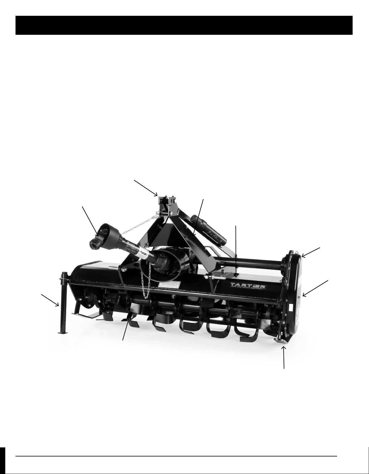
In order to provide a better view, certain photographs
or illustrations in this manual may show an assembly
with a safety shield removed. However, a Tarter
implement should never be operated in this condition.
Keep all shields in place. If shield removal becomes
necessary for repairs, replace the shield prior to use.
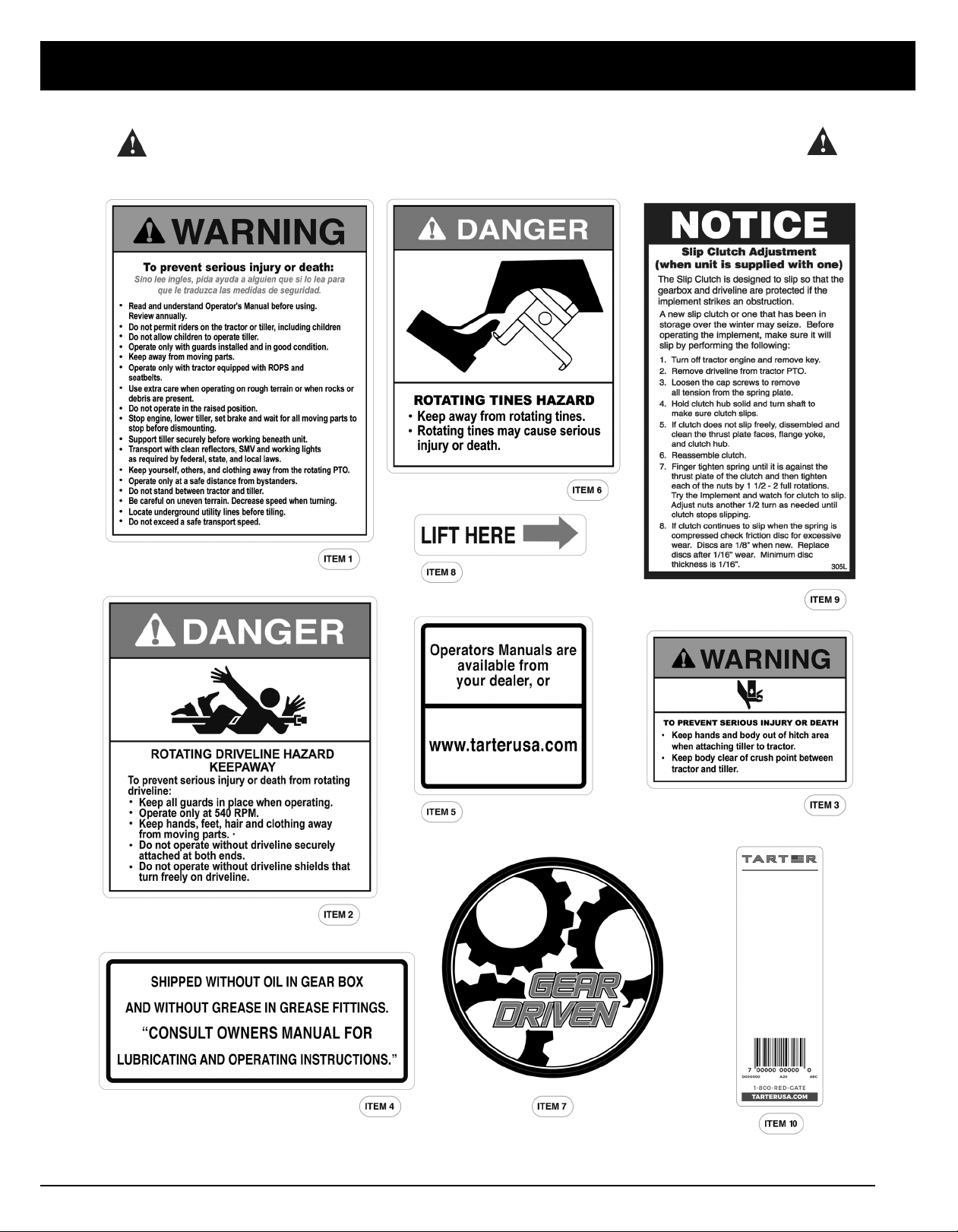
Replace any safety decal that is illegible or missing.
Location of such safety decals are indicated in this
manual.
Never use alcoholic beverages or drugs that can
hinder alertness or coordination while operating the
power unit or the Tarter implement. Consult your
doctor about operating this machine while taking
prescription medications.
Under no circumstances should children under the
age of 18 be allowed to operate the power unit or the
Tarter implement. Do not allow persons to operate
or assemble the Tarter implement until they have
read this manual and have developed a thorough
understanding of the safety precautions and how it
works. Review the safety instructions with all users
annually.
This Tarter implement can be dangerous to children
and persons unfamiliar with its operation. The
operator should be a responsible, properly trained and
physically able person familiar with farm machinery
and trained in this Tarter implement’s operations.
Always use a power unit equipped with a Roll Over
Protective System and seat belts(ROPS). Keep your
seat belt securely fastened because falling off can
result in your death from being run over or crushed.
Always keep a foldable ROPS system in the “locked
up” position at all times.
Never exceed the limits of any piece of machinery,
whether the power unit of the Tarter implement. If its
ability to perform a job safely is in question DO NOT
TRY IT.
Do not modify the Tarter implement in any way.
Unauthorized modification could result in serious
injury or death and may impair the function and life of
the implement.
In addition to the design of this implement, including
safety signs and safety equipment, hazard control
and accident prevention are dependent upon the
awareness, concern, prudence, and proper training
of personnel involved in the operation, transport,
maintenance and storage of the Tarter implement.
Refer also to safety messages and operation
instruction in each of the appropriate sections of the
power unit and Tarter implement manuals. Heed the
safety signs affixed to both the power unit and Tarter
implement.
Follow all safety rules and safety decal information.
Your Tarter implement is attached to a power unit.
You must know the controls of your power unit and
how to stop the engine and implement quickly in an
emergency. All operators must be capable to safely
operate the power unit, its attachments, and all
controls.
PREPARATION
Always wear relatively tight and belted clothing to
avoid getting caught in any moving part. Wear sturdy,
rough-soled work shoes and protective equipment for
eyes, hair, hands, ears, and head. Wear respirator or
filter mask when appropriate.
DANGER: Failure to follow instructions or
safety rules can result in serious injury or
death.
DANGER: DO NOT allow anyone to operate
the power unit or the Tarter implement
without proper instruction.

9
SAFETY
Before using the Tarter implement, check all driveline
guards for damage and replace any damaged guards.
Make sure all guards rotate freely on all drivelines.
Inspect chain or rubber guards before each use and
replace any that are damaged.
Check that all hardware is properly installed.
Always tighten to torque chart specifications unless
instructed otherwise in this manual.
Make sure the Tarter implement is properly secured,
adjusted and in good operating condition.
Before using the Tarter implement, check and adjust
PTO driveline length as instructed in this manual. The
driveline must not bottom out or pull apart throughout
the full range of the tractor hitch.
Make sure PTO driveline shield safety chain is
attached as shown in this manual and replace if
damaged or broken. Make sure collar slides freely and
is seated firmly in tractor PTO spline groove.
A minimum of 20% of tractor weight must be on the
tractor’s front wheels when Tarter implements are in
use. Without this weight, the tractor could tip over,
causing personal injury or death. The weight may be
attained with a loader, front wheel weights, ballast in
tires or front tractor weights. Weigh the tractor and
Tarter implement. DO NOT ESTIMATE.
STARTING AND STOPPING
Check the Tarter implement master shield over the
PTO stub shaft. Make sure it is in good condition and
fastened securely to the power unit. Purchase a new
shield if old shield is damaged or missing.
All power units that are not equipped with a “live”
power takeoff (PTO) must be equipped with an over-
running PTO clutch. These are available through most
farm equipment stores.
The Tarter implement is operated from power supplied
from the power unit PTO. Refer to the power unit
manual for PTO engagement and disengagement
instructions.
Understand how to stop the power unit and Tarter
implement quickly in case of an emergency.
When engaging the PTO, the engine RPM should
always be at idle speed. Once engaged and ready
to start, raise PTO speed to 540-RPM and maintain
throughout operation.
TRANSPORTATION
Never transport the power unit or the Tarter implement
while under the influence of alcohol or drugs.
Always comply with all federal, state and local laws
regarding lighting, marking requirements and
transportation of farm equipment on a public roadway.
Transport only in daylight or satisfactory artificial light.
Be aware of overhead utility lines.
Never allow riders on the power unit or Tarter
implement. Do not operate PTO during transport.
Watch for hidden hazards on the terrain during
transport.
Do not operate or transport on steep slopes.
Do not stop, start or change directions suddenly on
slopes.
Use extreme care and reduce ground speed on
slopes and rough terrain. When encountering rough
terrain during transport, reduce the power unit speed
to minimize the horizontal movement of the Tarter
implement.
Stabilizer bars should be used during transport to
reduce lateral movement of the Tarter implement.
Ensure the towing vehicle and trailer are safely
capable of transporting the Tarter implement and that
everything is properly secured.
IMPORTANT: DO NOT operate PTO until
driveline length is correct.
NOTE: The addition of an over-running
PTO clutch may change the length of the
PTO driveline required. Be sure to refer
to the instructions on the PTO driveline
installation. Be sure that the driveline
system guarding is adequate.

10
SAFETY
OPERATION
Never operate the power unit or the Tarter implement
while under the influence of alcohol or drugs.
Operate only in daylight or satisfactory artificial light.
Do not allow bystanders in the area when operating,
attaching, removing, assembling or servicing the
power unit or Tarter implement.
Never discharge directly toward people, animals or
property.
Ensure the rear-guard assembly is in place to reduce
the possibility of objects being thrown.
This Tarter implement is intended for agricultural
applications only. Do not operate within 300 feet of
bystanders or public roads or highways.
Keep hands, feet, hair and clothing away from the
power unit and Tarter implement while the power unit
engine is running. Stay clear of all moving parts.
Always sit in the power unit seat when operating
controls or starting engine. Securely fasten seat
belt, place transmission in neutral, engage brake
and ensure all other controls are disengaged before
starting the power unit engine.
DO NOT EXCEED the power unit PTO at 540 RPM.
Look down and to the rear and make sure area is clear
before operating in reverse. REVERSE OPERATION IS
NOT RECOMMENDED.
Be aware that turning the power unit tightly may cause
the Tarter implement to come in contact with the rear
wheels of the power unit and cause damage or injury.
Watch for hidden hazards on the terrain during
operation.
Do not operate on steep slopes.
Do not stop, start or change directions suddenly on
slopes.
Use extreme care and reduce ground speed on
slopes and rough terrain. When encountering rough
terrain, reduce the power unit speed to minimize the
horizontal movement of the Tarter implement.
Stop the power unit and equipment immediately
upon striking an obstruction. Turn off engine, remove
key, inspect, and repair any damage before resuming
operation.
MAINTENANCE
Make certain all movement of the power unit and
Tarter implement components has stopped before
approaching for service.
Before detaching the power unit from the Tarter
implement or performing any service or maintenance,
follow these steps: disengage power to the power unit,
lower the 3-point hitch and all raised components to
the ground, set parking brake, stop engine, remove
key and unfasten seat belt. Before performing any
service or maintenance, disconnect driveline from
tractor PTO.
Before working underneath the power unit or a Tarter
implement, carefully read this manual’s instructions,
disconnect driveline, raise implement, securely block
up all corners with jack stands, and check stability.
Secure blocking prevents a Tarter implement from
dropping due to hydraulic leak down, hydraulic
system failures or mechanical component failures.
Never go underneath a Tarter implement (lowered to
the ground or raised) unless it is properly blocked and
secured. Never place any part of the body underneath
the power unit or a Tarter implement or between
moveable parts even when the engine has been
turned off. Hydraulic system leak down, hydraulic
system failures, mechanical failures, or movement of
control levers can cause a Tarter implement to drop or
rotate unexpectedly and cause severe injury or death.
Follow the power unit and Tarter implement manual
for working underneath and blocking procedures.
Always wear relatively tight and belted clothing to
avoid getting caught in moving parts. Wear sturdy,
rough-soled work shoes and protective equipment for
eyes, hair, hands, ears, and head. When appropriate
wear a respirator or filter mask.

11
SAFETY
Keep all persons away from you while performing
adjustments, service or maintenance.
Frequently check blades/tines/shanks. They should
be sharp, free of nicks and cracks and securely
fastened. Do not handle blades/tines/shanks with
bare hands. Careless or improper handling may result
in serious injury.
Do not modify, alter, or permit anyone else to modify
or alter the power unit, the Tarter implement or any of
their components in any way, except as outlined in this
manual.
STORAGE
Always use a power unit to position a Tarter
implement for storage.
Block the Tarter implement securely for storage.
Keep children and bystanders away from storage area.
OPERATING INSTRUCTIONS
1. Before each use, perform all necessary
maintenance described in the maintenance
section.
2. Read, understand and follow the safety
information pertaining to training, preparation,
starting and stopping, operation, transportation,
maintenance and storage at the beginning of this
manual.
WARNING: Never attempt to move Tarter
implement by hand.

12
*Remove the hardware box and
set aside.
(Hardware box contents are
listed on pg. 28).
4. Remove the front guard plate.
5. Insert lift strap and slowly lift tiller.
6. With pressure relieved for the bolts, remove the
bolts from the tiller rack, using ¾” wrenches.
*BOLTS AND NUTS CAN BE DISCARDED.
TOOLS REQUIRED
• TIN SNIPS
• SOCKETS AND WRENCHES - 9/16”, 3/4”, 15/16”,
AND 1-1/4”. (IMPACT WRENCH IS PREFERRED)
1. With Rotary Tiller still in the rack, set it on a level
spot for assembly.
2. Remove the PTO Shaft, leaving the chains attached
to the PTO.
3. Remove lift arms and backstraps using a ¾”
wrench. Set aside after removing.
*BOLTS CAN BE DISCARDED.
ASSEMBLY
DANGER: Be cautious of weight shifting
when lifting.

13
ASSEMBLY
7. Before setting on level ground, remove the pin
from the kick stand, flip the kick stand over and set
at desired height.
8. Adjust skid shoe as needed.
9. Set the Rotary Tiller on level ground.
10. Install the lift arms onto
the Rotary Tiller, using
the CAT I pins and the
5/8” x 2” Grade 5 bolts,
with nuts and washers,
on the inside of the deck
bracing.
*CAT I pins are installed in the front hole and (2) 5/8” x
2” Grade 5 bolts are installed in the rear.
11. Attach the rounded end of the backstraps to the
outside of the rear tiller deck bracing using (2) 5/8” x
2” Grade 5 hex bolt with nuts and lock washers.
12. Repeat for opposite side.
13. Attach the square end of the backstraps to the inside
lift arms plates using the 1-1/2” spacer and 5/8” x 4”
hex bolt, nuts and lock washers.

14
14. Using the 5/8” x 4” hex bolt, install the 2-1/4”
spacer.
15. Attach the front guard plate to the lift arm plates
using (4) 3/8” x 1” hex bolt, nuts and lock washers.
16. Fully tighten all bolts.
17. Install the PTO guard using (4) ¼ ” x ¾” hex bolts
and flat washers. Make sure the opening on the
PTO guard is on the top.
18. Install PTO driveline.
ASSEMBLY
19. Remove the bolt from the PTO shaft. Slide the PTO
shaft onto the gearbox and reinstall the bolt through
the opening in the PTO shaft guard.
20. Assembly of your Rotary Tiller is now complete.
Please read the next section of this manual for filling
gearboxes with oil and lubricating instructions and
sizing your PTO (if applicable).

15
7. Using a 7/8” wrench, remove the ½” pipe plug
located at the top of the side gearbox and a 9/16”
wrench to remove the 1/8” check plug located on
the side of the side gearbox.
8. Fill the side gearbox using specified gear oil until
the oil begins to overflow from the check plug
hole. (Holds approx. 2-1/2 quarts.)
9. Replace and tighten the ½” vented pipe plug and
the 1/8” check plug. Clean away any excess oil.
10. Grease the grease fitting on the out-board hub.
11. Grease the two grease fittings on the PTO
universal joints.
12. Grease the two grease fittings on the PTO safety
shield.
13. Separate the PTO shaft and grease the inner
surface.
ASSEMBLY
BEFORE PUTTING YOUR
ROTARY TILLER INTO SERVICE
NOTE: Fill the gearboxes using EP 85-90W gear oil.
For all grease fittings use TYPE/Grade II tube grease.
1. Please ensure that your Rotary Tiller is secure and
level.
2. Using a 7/8” wrench, remove the ½” vented pipe
plug located on top of the gearbox.
3. Using a 9/16” wrench, remove the check plug,
located on the back of the gearbox.
4. Fill the gearbox using specified gear oil, until oil
begins to overflow from the check plug hole in the
rear. (Holds approx. 1-1/2 quarts.)
5. Replace and tighten the check plug.
6. Replace and tighten the ½” vented pipe plug and
clean away any excess oil.
IMPORTANT: DO NOT overfill gearbox. This
could cause damage to oil seals and can
cause permanent damage to the gearbox.
This issue will not be covered under
warranty.
IMPORTANT: DO NOT overfill gearbox. This
could cause damage to oil seals and can
cause permanent damage to the gearbox.
This issue will not be covered under warranty.
IMPORTANT: This tiller was shipped without
oil in the gearboxes and without grease in the
the grease fittings.
UNIT MUST BE SERVICED BEFORE USE.

16
ATTACHING
8. Make sure driveline is properly installed and level
before checking driveline collapsible length.
9. With driveline level, measure 1” back from universal
joint shield to end of outer driveline shield. If
measurement is less than 1”, then shorten driveline
using instructions provided in section “Sizing The PTO
Shaft”.
ATTACHING TO A TRACTOR
1. Place tiller and tractor on level ground.
2. Back tractor into position by lining up lift arms
and Category I pins on the tiller. Attach lift arms to
Category I pins and secure with lynch pins.
3. Attach top link using Category I lift pin and lynch pin.
4. Attach PTO driveline and secure anti-rotation chains.
5. Once everything is securely attached, raise tiller off
the ground and adjust the top link so the tiller sets
level from front to back.
6. Determine if the PTO shaft needs to be shortened.
7. Always check driveline collapsible length during initial
setup, when connecting to a different tractor and
when alternating between using a quick hitch and a
standard 3-point hitch. More than one driveline may
be required to fit all applications.
IMPORTANT: A driveline that is too long to
fit between tractor and tiller will bottom out
causing structural damage to the tractor
and tiller

17
4. Round off all sharp edges and remove burrs.
Grease sliding profiles. No other changes may be
made to PTO drive shaft and guard.
5. Chains must be fitted so as to allow sufficient
articulation of the shaft in all working positions.
6. The PTO drive shaft must not be suspended from the
chains.
Final Inspection and Adjustments
IMPORTANT: PTO driveline may be too long for some tractor models, causing tractor transaxle damage.
Modify driveline if necessary.
Attach Rotary Tiller to tractor and check tiller-to-tractor driveline telescoping length clearance.
(See MAINTENANCE BEFORE EACH USE in Lubrication and Maintenance section.)
Modify PTO Driveline (If Necessary)
1. To adjust the length, hold the half-shafts next to each
other in the shortest working position and mark them.
2. Shorten inner and outer guard tubes equally.
3. Shorten inner and outer sliding profiles by the same
length as teh guard tubes.
MODIFY PTO DRIVELINE
MODIFYING PTO

18
INNER SHAFT
INNER DRIVELINE
OUTER DRIVELINE
INNER SHIELD
OUTER SHAFT
OUTER SHIELD
UNIVERSAL
JOINT SHIELD
TRACTOR END
IMPLEMENT END
Figure 1 - Driveline Shortening
A
B
B
X
Y
X1
Y1
FREE LENGTH IMPLEMENT END
INNER PROFILEOUTER PROFILE
1/3 1/3 1/3 1/3 1/3
OVERLAP
MAXIMUM ALLOWABLE LENGTH
Outer Shielding has been removed for clarity.
FREE LENGTHTRACTOR END
Figure 2 - Driveline Maximum Extended Length
MODIFYING PTO
SIZING THE PTO SHAFT
Refer to Figure 1
1. Detach the driveline from tractor PTO shaft and pull
outer and inner drivelines apart.
2. Reattach outer driveline to tractor PTO shaft. Pull on
inner and outer drivelines to ensure universal joints
are properly secured.
3. Hold inner and outer drivelines parallel to each other:
a. Measure 1” (“B” dimension) back from
outer driveline universal joint shield and
make a mark at this location on the inner
driveline shield.
b. Measure 1” (“B” dimension) back from
inner driveline universal joint shield and
make a mark at this location on the outer
driveline shield.
4. Remove driveline from tractor and gearbox shafts.
5. Measure from end of inner shield to scribed mark (“X”
dimension). Cut off inner shield at the mark. Cut same
amount off the inner shaft (“X1” dimension).
6. Measure from end of outer shield to scribed mark (“Y”
dimension). Cut off outer shield at the mark. Cut same
amount off the outer shaft (“Y1” dimension).
7. Remove all burrs.
8. Continue with “Check Driveline Maximum Length”.
CHECK DRIVELINE MAXIMUM
LENGTH
Refer to Figure 2
Make sure driveline’s collapsible length is acceptable.
The driveline maximum allowable length must, when fully
extended, have a minimum overlap of the profile tubes by
not less than 1/3 the free length with both inner and outer
profile tubes being of equal length.
1. Apply multi-purpose grease to the inside of the outer
shaft and reassemble the driveline.
2. Assemble the two driveline profiles together with
1/3 of the profile tubes overlapping as shown below.
Once assembled, measure and record the maximum
allowable length for future reference.
3. Attach inner driveline yoke to the tiller’s gearbox shaft.
Attach outer driveline yoke to the tractor’s PTO shaft.
4. Move yoke ends of driveline back and forth to insure
they are secured to the tractor and tiller shafts.
Reattach any end that is loose.
5. Hook driveline safety chain on the tractor end of
driveline to tiller frame. Re-latch safety chain to the
driveline shield.
6. Hook driveline safety chain on the Rotary Tiller end
of driveline to the tiller frame. Re-latch safety chain to
driveline shield.
IMPORTANT: Small chains are supplied with
the driveline. They must be attached to the
inner and outer driveline shields and to the
tiller and tractor to restrict shield rotation.

19
DRIVELINE
LEVEL
Figure 3 - Check Driveline Maximum Angle
MODIFYING PTO
7. Start tractor and raise Rotary Tiller just enough to
remove support blocks.
8. Slowly engage tractor hydraulic 3-point control
lever to lower the tiller while checking for sufficient
drawbar clearance. Move drawbar in, aside or remove
if required.
9. Raise and lower implement to find maximum
extended driveline length. Check to make certain the
driveline does not exceed maximum allowable length
recorded in step 2.
10. If needed, set tractor 3-point lift height to stop
driveline from exceeding maximum allowable length.
11. Continue with “Check Driveline Maximum Angle”
below.
CHECK DRIVELINE MAXIMUM
ANGLE
Refer to Figure 3
1. Raise and lower implement to find maximum driveline
angle. Check to make certain the driveline does not
exceed 25° up or down.
2. If needed, set tractor 3-point lift height to keep driveline
from exceeding 25° up.
IMPORTANT: To avoid premature driveline
breakdown, do not exceed an angle of 25°
up or down with the driveline while driveline
is rotating. If needed, set tractor 3-point left
lever to limit driveline angle at a maximum of
25° up.

20
OPERATING INSTRUCTIONS
1. With the Rotary Tiller positioned on level ground,
adjust the tractor lift arms so that when lifted, the
rotor bar remains parallel to the ground.
2. With the Rotary Tiller attached to the tractor, raise
and support the tiller with suitable blocks. Adjust the
skids, located on the sides of the tiller. The adjustment
bolts for both right and left sides should be adjusted
in the same hole. This allows the tiller to till the same
depth on each side. Adjust the rear guard assembly,
with regulating chain, until the desired mulching effect
is found.
3. Raise the tiller and remove the blocks.
4. With the tractor at idle RPM and the tiller lifted off the
ground, engage the PTO and slowly advance throttle
to 540 PTO RPM.
5. Select a low gear for the tractor and begin to move
forward. Tractor ground speed is to be controlled
by gear selection only and not engine speed. As the
tractor moves forward, slowly lower the tiller down.
Allow the tiller tines to gradually engage the ground.
6. After each use clean all debris from the tiller tines.
Replace any missing or illegible safety decals. Inspect
for any damaged or worn parts and replace before
next use. Store Rotary Tiller in a dry environment.
MAINTENANCE
1. Periodically check and maintain proper gear oil level.
2. Every 8 hours, grease: (1) outboard hub, (2) PTO shaft
universal joints, (3) PTO shaft safety shield and (4)
PTO telescoping surface.
3. Check tiller tines for cracks and breaks before every
use.
4. Slip clutch operational check. After the implement
has been stored for thirty days or more perform the
following operational check.
a. Loosen bolts and lock nuts progressively until
tension is relieved.
b. To aid in determining slippage, scribe/mark a
line across clutch plate and Belleville Spring.
c. With tractor at idle speed, engage tractor PTO
drive 2-3 seconds. Clutch should slip without
turning blades.
d. To retighten the slip clutch, tighten the torque
spring bolts until the nut makes contact with the
flange yoke and further tighten one and a (1-1/2)
half turns.
OPERATINGMAINTENANCE
IMPORTANT: Do not allow the tractor
engine or Rotary Tiller to bog down or stall.
This causes undue wear and tear on the
tiller and tractor.
NOTE: While this is a good starting point,
further adjustments may need to be made
based on soil conditions.
IMPORTANT: Slip clutch components must
be free to rotate when necessary. After thirty
days or more, linings of slip clutch may draw
moisture. Linings may bond to metal parts
causing slip clutch to be ineffective, resulting
in machine damage.
Other manuals for RT205BL
1
This manual suits for next models
2
Table of contents
Other Tarter Farm Equipment manuals

Tarter
Tarter BOX BLADE User manual

Tarter
Tarter CBFG User manual

Tarter
Tarter VALUE 90 SWEEP TUB 90ST Manual

Tarter
Tarter CBFG User manual

Tarter
Tarter ATVCPDC User manual

Tarter
Tarter CBFG User manual

Tarter
Tarter CattleMaster 120 User manual

Tarter
Tarter RC104BL User manual

Tarter
Tarter RT104BL User manual

Tarter
Tarter CattleMaster 12 Series Parts list manual