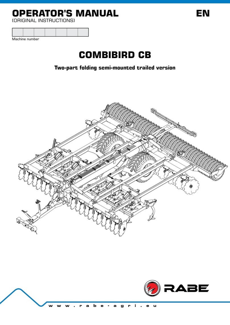
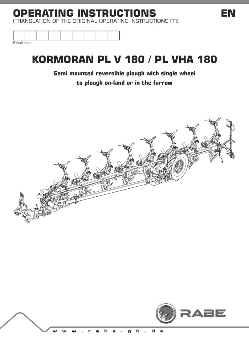
Rabe KORMORAN SF 180 User manual

www.rabe-gb.de
OPERATING INSTRUCTIONS EN
(TRANSLATION OF THE ORIGINAL OPERATING INSTRUCTIONS FR)
Serial-No.
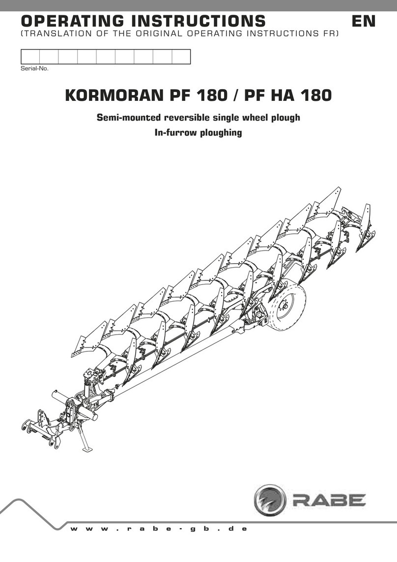
KORMORAN SF 180 / SF HA 180
Semi-mounted reversible single wheel plough
In-furrow ploughing


QUICK START KORMORAN SF 180 / SF HA 180
9901.00.07EN04SF - 02/2017 6XEMHFWWRWHFKQLFDOPRGL¿FDWLRQV
Quick start
KORMORAN SF 180 / SF HA 180
Preparing the tractor
1. Check the pressure of the tyres.
- It must be identical on each side of the tractor, both at the front
and back.
2. Adjust the length of the lower link arms.
- Adjust the length of the link arms so that the hitch is perfectly
horizontal for operation. The arm lengths must be adjusted
so that at least 30 mm of chrome remains visible on the lifting
cylinders when in operation.
3. Adjust the lateral play of the link arms.
- 7UDQVSRUWSRVLWLRQPLQSOD\FP
- Working position: 2 to 5 cm play.
4. Check the top link of the hitch.
- The connection between the top link of the tractor and the
implement must be made by means of a ball joint and not by
an automatic hook
Hitch
5. Hitch the lower arms.
6. Lift the yoke and release the latch.
7. Attach the top link.
8. Make sure that there are no obstacles between the
implement and the tractor.
- There must be no possibility of the implement touching the
tractor.
- There should never be any contact between the lower arms
of the tractor or the top link and the draw bar couplings of
the implement when it moves from the raised position to the
working position
9. Connect the hydraulic hoses and the function selector
10. Transport/working positions
ʈTransport position:
- Frame locked with bodies horizontal.
- Offset compass folded
- Safety stop placed on the wheel unit.
- With the implement lowered, check that there is no possibility
of contact with the ground. Leave a clearance of 30 to 50 mm
at the safety stop on the rear wheel.
ģWorking position:
- Frame unlocked.
- Offset compass open with the cylinder correctly positioned
- Safety stop removed from the rear wheel unit
1st pass
11. Adjust the working width.
12. Set the working depth with the wheel.
2nd pass
13. Fine-tune the depth adjustment with the depth
adjustment screw on the rear wheel.
14. Level the implement in the longitudinal direction
IURQWWRUHDU
15. Top link.
- This must be placed at a higher level on the implement side
than the tractor side.
- Adjust the length so that the yoke is parallel to the ground and
at the desired working depth.
16. Check the side-to-side levelling adjustment.
- The leg elements must be perpendicular to the ground (adjust
WKHWLOWDQJOHVFUHZ
17. Adjust the front furrow width.
- Adjust the opening of the offset compass so that the 1st body
works the same width as the others.
Maintenance
18. Service the implement as any other agricultural
equipment, follow the recommendations in the manual
This operating Instruction is also valid for the special model
Kormoran SP 180 / SP 180 HA series 2012 - 2013.


- 5 -
TABLE OF CONTENTS
Any use and / or reproduction of all or part of this manual without written authorization from Gregoire-Besson is strictly prohibited.
9901.00.07EN04SF - 02/2017 6XEMHFWWRWHFKQLFDOPRGL¿FDWLRQV
INTRODUCTION
1 Instructions..................................................7
1.1 Product documentation .......................................7
1.2 Explanation of symbols ........................................7
1.3 Regulations and legal provisions ...........................7
1.3.1 CE label ......................................................7
1.4 Identification of your equipment ...........................7
1.4.1 Type plate ...................................................7
1.4.2 Location of type plate ..................................7
1.4.3 Identification of your equipment ....................7
1.5 Associated documents ........................................7
2 Safety instructions and rules .........................8
2.1 Safety instructions .............................................8
2.1.1 General instructions ....................................8
2.1.2 Operator qualification ..................................8
2.1.3 Hitching and unhitching the implement...........8
2.1.4 Hydraulic circuit and couplings......................8
2.1.5 Use of the implement ...................................8
2.1.6 Transport on the public highway ....................9
2.1.7 Maintenance ...............................................9
2.1.8 Loading and unloading ..................................9
2.1.9 Safety stickers..........................................10
USE
3 Description of the implement .......................12
3.1 General views...................................................12
3.2 Technical specifications .....................................13
3.3 Technical characteristics - solid body..................13
3.4 Technical characteristics - slatted body ..............14
3.5 Technical characteristics - accumulator 0.75L ....14
3.6 Technical characteristics - accumulator 3.5L .....14
3.7 Dimensions and weights ....................................14
3.8 Rack and pinion assembly ..................................15
3.8.1 Offset slide ...............................................15
3.9 Hydraulic weight transfer control (optional).........16
3.10 The "Z" beam ....................................................16
3.11 Extensions (optional) .........................................17
3.12 The wheel unit ..................................................17
3.13 Working width ..................................................18
3.14 Mould board .....................................................18
3.15 Ploughshare .....................................................18
3.16 Fin coulter (Optional).........................................19
3.17 Deflector (Optional) .........................................19
3.18 Disc coulter [optional] .......................................19
3.19 Safety devices..................................................19
3.19.1 Mechanical safety device............................19
3.19.2 "Hydro Avant" hydraulic safety device
(optional) ..................................................19
3.20 Lighting and signals (optional) ............................20
4 Preparing the tractor..................................20
4.1 Required tractive power ....................................20
4.2 Tractor wheels .................................................20
4.2.1 Tractor tyres ............................................20
4.2.2 Tyre spacing.............................................21
4.3 Ballasting the tractor .......................................21
4.4 Length of the lifting links ...................................22
4.5 Position of the stabilisers..................................22
4.6 Top link. ...........................................................23
5 Hitching and unhitching ...............................23
5.1 Hitching the implement to the tractor ................23
5.1.1 Tractor equipped with link arms with fixed
ball joints ..................................................23
5.1.2 Tractor equipped with link arms with
removable ball joints ..................................23
5.1.3 Releasing the latch ....................................24
5.1.4 Hitching the top link...................................24
5.1.5 Electrical connection of the signalling
equipment.................................................24
5.1.6 Hydraulic connections ................................24
5.1.7 Position of support legs .............................25
5.2 Locking and unlocking the turnover mechanism ....25
5.3 Unhitching the implement from the tractor .........26
5.3.1 6.3.1 Decompression kit ............................26
6 Hydraulic connections ................................. 27
6.1 Required hydraulic control valves .......................27
6.2 Max. hydraulic ..................................................27
6.3 Hydraulic connections .......................................27
6.4 Function selector (optional)................................28
6.4.1 Installing the function selector....................28
6.4.2 Electrical connections of the solenoid valves 28
6.4.3 Using the function selector ........................29
6.4.4 Special characteristics of the selector ........29
7 Preparing the implement before work............30
7.1 Locating the adjustment points ..........................30
7.2 Working width adjustment .................................31
7.3 Wheel angle adjustment.....................................31
7.4 Calibration of non-stop hydraulic safety devices...32
7.5 Offset adjustment (width of 1st furrow) ...............33
7.6 Installing the subsoiler (optional) ........................34
7.7 Implement wheel ...............................................34
7.7.1 Tyre pressures ..........................................34
7.7.2 Tightening of wheel studs ...........................34
8 Changing between transport and working
position...................................................... 35
8.1 Changing to transport position...........................35
8.2 Changing to working position..............................35
8.3 Driving on the road ...........................................36
9 Field adjustment .........................................36
9.1 Use in the field .................................................36
- 6 -
TABLE OF CONTENTS
Any use and / or reproduction of all or part of this manual without written authorization from Gregoire-Besson is strictly prohibited.
9901.00.07EN04SF - 02/2017
6XEMHFWWRWHFKQLFDOPRGL¿FDWLRQV
9.2 First pass ........................................................37
9.2.1 Ground work .............................................37
9.2.2 Working depth adjustment..........................37
9.2.3 Tilt adjustment ..........................................38
9.3 Second pass.....................................................38
9.3.1 Longitudinal levelling ..................................38
9.3.2 Lateral levelling .........................................39
9.3.3 Mechanical or hydraulic offset adjustment
(width of 1st furrow) ...................................39
9.4 Adjusting the hydraulic compensation cylinder
(according to model)..........................................39
9.5 Agricultural work in the field - adjusting the
settings ...........................................................40
9.5.1 Safety during operations ............................40
9.5.2 Working instructions..................................40
9.5.3 Adjustments while working .........................40
9.6 Adjustment of the disc coulter (optional).............40
9.6.1 Set the working depth with the disc coulter.40
9.7 Disc coulter - lateral overlap adjustment.............41
9.7.1 Adjustment - Flat leg .................................41
9.7.2 Adjustment - Round leg ..............................41
9.7.3 Disc coulter - adjust the pivot arm end stop 42
9.8 Adjustment of round leg skimmers
(optional)..........................................................42
9.8.1 Round leg Skimmer - adjusting the working
depth .......................................................42
9.8.2 Round leg skimmer - adjusting lateral
overlap .....................................................43
9.8.3 Ropund leg skimmer - setting the discharge
angle ........................................................43
9.9 Adjustment of Vari- Fix skimmer (optional) ..........44
9.9.1 Vari-Fix - Adjusting working depth ...............44
9.10 Adjusting the Vari Heavy Duty skimmers.............45
9.10.1 Vari Heavy Duty - adjusting the working
depth .......................................................45
9.10.2 Vari Heavy Duty skimmers - lateral overlap..45
9.11 Adjustment of deflector (optional) ......................46
9.12 Adjusting the sub-soiler (optional) ......................46
MAINTENANCE
10 Protection of the environment......................47
10.1 Soil contamination ............................................47
10.2 Worn tyres.......................................................47
11 Cleaning .....................................................47
12 Inspection ..................................................47
12.1 Checking the hydraulic system ...........................47
12.1.1 Identification of a hydraulic hose .................48
12.2 Lubrication and greasing ...................................49
13 Troubleshooting and repair ........................... 53
13.1 Tripping the mechanical stone safety device -
replacing the shear bolt.....................................53
13.2 Replacing the shear bolt ....................................53
13.3 Replacing the Vari Heavy Duty (VHD) shear bolt..54
13.4 Replacing the sub-soiler shear bolt (optional) ......55
13.5 Adjust undercut................................................56
14 Replacing wear parts ..................................58
14.1 Replacing mouldboards ......................................58
14.2 Replace the stripes...........................................59
14.3 Replace the tine ...............................................59
14.4 Replace the tines with reversible points.............59
14.5 Replace the trash board ....................................60
14.6 Replace the subsoiler ........................................60
14.7 Replace the skimmer tines and mouldboard ........61
14.8 Replace the disc coulter ....................................61
15 Replacing the wheel ....................................62
16 Spare parts................................................64
16.1 Maintenance of plough bodies ............................64
16.2 Tightening torques ............................................64
16.3 Precautions for storage ....................................65
16.3.1 Placing the sub-soiler in the rest position ....65
16.4 Returning to operation and additional check ........65
17 CE declaration ............................................ 66

- 7 -
OPERATOR'SMANUAL KORMORAN SF 180 / SF HA 180
9901.00.07EN04SF - 02/2017 6XEMHFWWRWHFKQLFDOPRGL¿FDWLRQV
INTRODUCTION
1 INSTRUCTIONS
1.1 Product documentation
This manual forms an integral part of the implement, and in
the event of sale, it must be passed on with the implement in
compliance with the applicable regulations.
ʈRead this manual carefully so that you understand all the
information contained, ensuring completely safe operation and
service. We reject any liability for damages caused by non-
observance of the instructions in this manual.
1.2 Explanation of symbols
CAUTION:
Risk of physical injury.
Risk of damage to the implement or to its
surroundings.
DANGER:
Risk of electric shock.
IMPORTANT:
Useful information.
1.3 Regulations and legal provisions
1.3.1 CE label
The CE label shows that the implement described in this manual
complies with the following directive:
ʈ0DFKLQHU\GLUHFWLYHGLUHFWLYH(&
1.4 Identification of your equipment
1.4.1 Type plate
The type plate contains the following information:
234
15
Legend
1 Implement serial number
2 Model type of implement
3 Address and country of manufacture
4 Name of manufacturer
5 Year and month of manufacture of implement
1.4.2 Location of type plate
1
Legend
1 Type plate
1.4.3 ,GHQWL¿FDWLRQRI\RXUHTXLSPHQW
Please enter below the date of purchase, the model and
VHULDOQXPEHURI\RXULPSOHPHQWUHIHUWRWKHW\SHSODWH7KLV
information will be required for all orders for replacement parts or
service.
)LOORXWDQGUHWXUQWKHUHJLVWUDWLRQIRUPSDUWVIRUWKHZDUUDQW\
Purchase date: ..............................................................................
Model: ............................................................................................
Serial number: ...............................................................................
Telephone number of your agent or dealer: ...................................
.......................................................................................................
Explanation of type designation:
ʈKormoran SF HA 180
- S: Standard
- F: In-furrow ploughing
- HA: HydroAvant hydraulic stone protection system
- 180: Frame dimensions 180 mn x 180 mm
1.5 Associated documents
- 1 operator's manual.
- 1 catalogue of replacement parts

- 8 -
OPERATOR'SMANUAL KORMORAN SF 180 / SF HA 180
9901.00.07EN04SF - 02/2017
6XEMHFWWRWHFKQLFDOPRGL¿FDWLRQV
2 SAFETY INSTRUCTIONS AND
RULES
2.1 Safety instructions
2.1.1 General instructions
CAUTION:
The risks of accidents during use, maintenance or
repair of the implement can be reduced if you follow
the safety instructions and preventative measures
described in this manual.
ʈOnly the operations and manoeuvres described in this manual
may be performed. The manufacturer is not able to predict
all possible situations involving risks. As a result, the safety
instructions described in the manual and on the implement are
not exhaustive.
ʈAs a user, you must make reasonable allowance for possible
risks to yourself, others and implement while you are using it.
CAUTION:
Non-observance of safety and usage instructions,
repair or maintenance instructions for your
implement can result in serious, even fatal
accidents.
2.1.2 2SHUDWRUTXDOL¿FDWLRQ
ʈThe implement may only be used, serviced or repaired by
SHUVRQVZKRDUHIDPLOLDUZLWKLWVVSHFL¿FFKDUDFWHULVWLFVDQG
with the corresponding operational safety modes.
ʈBefore using your implement, familiarise yourself with all the
controls and with its proper operation.
2.1.3 Hitching and unhitching the implement
ʈIf there is only one operator, then the driver himself is
responsible for hitching and unhitching the implement. Use the
external lift controls.
ʈMake sure that no-one can get between the tractor and the
implement or come close to the implement during the hitching
and unhitching operations.
ʈBefore getting out of the cab to hitch or unhitch the implement,
apply the parking brake, stop the engine and take out the
tractor ignition key.
ʈBefore hitching your implement, make sure that there are no
signs of wear, incipient cracks or any incompatibility with your
tractor on the hitching pins, draw bar hitches or the ball joints.
ʈDepressurise the hydraulic circuit before connecting or
disconnecting the hydraulic couplings.
ʈConnect or disconnect the electrical connections.
ʈCompletely lower the implement to the ground, position the
VXSSRUWOHJVRIWKHLPSOHPHQWEHIRUHXQKLWFKLQJLW0DNHVXUH
WKDWWKHVXUIDFHLVOHYHODQGVXI¿FLHQWO\¿UPWRHQVXUHWKDWWKH
implement is perfectly stable during storage.
ʈIf your implement is parked, make sure that it is stable to avoid
the possibility of physical injury or material damage.
2.1.4 Hydraulic circuit and couplings
CAUTION:
The hydraulic circuit is subject to high pressures.
ʈ,IK\GUDXOLFÀXLGVKRXOGHVFDSHDYRLGDQ\GLUHFWFRQWDFWZLWK
WKHK\GUDXOLFÀXLG7KHSUHVVXULVHGRLOFDQSHQHWUDWHWKHVNLQ
and cause fatal injuries. Immediately consult a doctor in the
event of injury.
ʈObserve the order of assembly of the hydraulic couplings.
Ensure that the tractor couplings are properly positioned
horizontally or vertically.
ʈBefore connecting the hydraulic circuit, clean the couplings on
the tractor and implement, and check that the pressure is zero
both on the tractor and implement side.
ʈReplace damaged or used hydraulic lines, observing the
GLPHQVLRQDOVSHFL¿FDWLRQV
ʈFor all actions on the hydraulic system, set the implement
down on the ground, depressurise the hydraulic circuit, stop
the tractor engine and actuate the hydraulic valves.
2.1.5 Use of the implement
ʈThis implement is exclusively designed for standard
agricultural work. Any other use is considered to be contrary to
the implement's normal use and is thus prohibited.
ʈDo not attempt to adjust an implement when this is in motion.
ʈDo not enter the pivoting range of bolted, hydraulic or
mechanical locking elements.
ʈWear clothing and personal protection equipment suited to
the work to be performed (thick leather gloves, safety boots,
SURWHFWLYHJODVVHV«
ʈCreate a safety perimeter for other persons.
ʈ'RQRWSHUIRUPDQ\DGMXVWPHQWZRUNZLWKRXW¿UVWKDYLQJ
perfectly understood the required procedure.
ʈUse suitable tools or equipment for the work to be performed.
ʈCorrectly use the implement and its controls, do not let
untrained persons attempt to operate it.
ʈDo not extend the mechanical adjusting rods to avoid the risk
of threads being torn or spontaneous unscrewing.

- 9 -
OPERATOR'SMANUAL KORMORAN SF 180 / SF HA 180
9901.00.07EN04SF - 02/2017 6XEMHFWWRWHFKQLFDOPRGL¿FDWLRQV
ʈWhen working alone, the operator must be in his cab and
may never leave his seat. No-one may ride or stand on the
implement when it is in operation.
ʈStop the implement if you notice unusual noises or vibrations.
Identify and eliminate the cause before resuming work.
CAUTION:
If the implement is equipped with a hydraulic folding
mechanism, only actuate this from the tractor cab.
Make sure that there is no possibility of anyone
being in the pivoting zone of the side sections or of
the rear accessories.
2.1.6 Transport on the public highway
ʈThe implements must always be transported in accordance
with the applicable directives and regulations relating to the
prevention of accidents, road safety and occupational health.
ʈBefore transporting the implement, ensure that the wheel
VWXGVDQGWKH¿[LQJEROWVIRUWDQGHPLPSOHPHQWVLIWKH
LPSOHPHQWLVHTXLSSHGZLWKWKHODWWHUDUHVHFXUH&KHFNWKH
pressure and condition of the tyres:
- Do not drive on roads with low pressures, or with damaged
tyres or wheel rims.
ʈDuring road transport, use all the lighting and signal devices
required by the law applicable in the country of use. If
UHTXLUHGWKH\FDQEHUHWUDFWHGGXULQJ¿HOGZRUNWRDYRLGDQ\
damage to them.
ʈThe user is responsible for compliance with the applicable
regulations and keeping up to date with changes.
ʈ5HJXODUO\FKHFNWKHFRQGLWLRQDQG¿[LQJRIWKHKLWFKLQJSLQV
and do not hesitate to replace them if they are worn.
The tractor hitch ball joints may also show signs of wear; do
not hesitate to replace them with new ones.
ʈDrive at a reasonable speed and in compliance with legislation
so that you are always in control of the hitched assembly. Be
especially careful in rough terrain or on slopes. Before starting
to drive downhill, shift into low gear.
ʈThe tractor used for transporting the implement on road must
have the same weight and same power rating as that used for
¿HOGZRUN
ʈNever attempt manoeuvres when anyone else is in the vicinity
of the implement or the tractor.
ʈFor implements equipped with a fold-in mechanism for
transport, make sure that no persons or objects are present
in the danger zone when the respective sections are being
folded in.
ʈObserve all the common sense rules when driving, especially
in bends in the road and where it is narrow.
ʈTake all required precautions before leaving the tractor. Apply
the parking brake, stop the engine and take out the ignition
key.
ʈIt is prohibited for anyone to ride on the implement or between
the implement and tractor when driving on public highways.
2.1.7 Maintenance
ʈThe maintenance area must be clean, dry, well ventilated and
well lit.
ʈIf it is necessary to work on or remove an implement
subassembly in a raised position, prop up the implement in
DV\VWHPDWLFPDQQHUE\PHDQVRIVXLWDEOHDQGVXI¿FLHQWO\
strong supports.
ʈFor repairs to components under pressure or under tension
DFFXPXODWRUVVSULQJVHWFUHIHUWRWKHVSHFL¿FSURFHGXUHV
and equipment. Such repairs must only be performed by
TXDOL¿HGSHUVRQV
ʈAfter the work is completed, make sure that all equipment and
tools used have been removed.
ʈ5HJXODUO\FKHFNWKDWWKHZKHHOVVWXGVWKHORZHU¿[LQJQXWVIRU
wearing parts, screws and bolts are secure.
ʈAlways use original replacement parts as only these meet the
PDQXIDFWXUHUVWHFKQLFDOVSHFL¿FDWLRQV
2.1.8 Loading and unloading
- Loading and unloading with a tractor.
ʈHitch the implement to or unhitch it from the tractor before
loading it onto a truck or unloading it from a truck.
ʈLoading and unloading the implement: an assistant is required
to guide the manoeuvres.
ʈAttach or remove the transport safety devices.
- Loading and unloading with the aid of a crane.
CAUTION:
2QO\DWWDFKWKHOLIWLQJJHDUWRWKHVSHFL¿HG¿[LQJ
SRLQWVZLWKWKHDLGRIVXLWDEOH¿[LQJV1HYHUVWDQG
under a raised or unsecured load.

- 10 -
OPERATOR'SMANUAL KORMORAN SF 180 / SF HA 180
9901.00.07EN04SF - 02/2017
6XEMHFWWRWHFKQLFDOPRGL¿FDWLRQV
2.1.9 Safety stickers
CAUTION:
Take care not to damage the safety stickers when
washing the implement.
IMPORTANT:
Replace damaged or missing stickers.
Locations of the safety stickers.
Legend
1 "25" sticker
2 "Safety triangle" sticker
3 "Crushed feet zone" sticker
4 "Stop engine and remove the key" sticker
5 "Stay outside left-hand working zone" sticker
6 "Stay outside the working zone" sticker
7 "Do not climb onto the implement" sticker
8 "Shoe adjustment" sticker
9 "Pivoting zone” sticker
10 "Wheel tightening" sticker
11 "Crushing hazard zone" sticker
12 "Carrier loading zone" sticker (according to model)
13 "Hydraulic leak" sticker
14 "Accumulator explosion zone" sticker (according to model)
15 "Locking device" sticker
16 "Read the operator's manual" sticker
17 "Locking device" sticker
18 "Stay outside right-hand working zone" sticker
5HÀHFWLYHGHYLFHRSWLRQDO
20 "Re-tighten all bolts" sticker
9998.02.58
9998.02.85
9998.02.85
9998.02.58
Legend
21 "Accumulator explosion zone" sticker
22 "Location of lubrication points" sticker

- 11 -
OPERATOR'SMANUAL KORMORAN SF 180 / SF HA 180
9901.00.07EN04SF - 02/2017 6XEMHFWWRWHFKQLFDOPRGL¿FDWLRQV
Explanation of stickers
Sticker Description
UI 1857
Crushed feet zone
Maintain a safe distance from all moving parts.
UI 1828
Stop engine and remove the key
Stop the engine and remove the ignition key
before any maintenance or repair work.
UI 1847
Stay outside left-hand working zone
Always stay out of the working area of the three-
point linkage when using the remote control.
UI 1841
Stay outside the working zone
Maintain a safe distance from all moving parts.
UI 1834
Do not climb onto the implement
Do not transport anyone on the implement.
UI 1851
Pivoting zone
Remain outside the pivoting zone.
UI 1863
Wheel tightening
Follow the instructions given in the operator's
manual.
UI 1861
Crushing hazard zone
Never work in a zone where there is a risk of
crushing while the parts are able to move.
Sticker Description
UI 1852
Truck loading zone
Location of implement's loading points.
UI 131
Locking device
Install the locking device before carrying out any
work in the danger zone.
UI 1832
Hydraulic Leak
Follow the instructions of the operator's manual
when performing servicing operations.
UI 1833
Read the operator's manual
Read the operator's manual and the safety
instructions before starting up the implement and
take account of them during operation.
UI 1830
Locking device
Install the locking device before carrying out any
work in the danger zone.
UI 1845
Stay outside right-hand working zone
Always stay out of the working area of the three-
point linkage when using the remote control.
9998.06.40
Re-tighten all bolts every 50 operating hours.
UI 1858
Accumulator explosion zone
The hydraulic accumulator contains gas and oil
under pressure. Follow the the instructions given
in the operator's manual for removal and repair
operations.
9998.02.58
Location of lubrication points
Adjust the lever end stop angle.

- 12 -
OPERATOR'SMANUAL KORMORAN SF 180 / SF HA 180
9901.00.07EN04SF - 02/2017
6XEMHFWWRWHFKQLFDOPRGL¿FDWLRQV
USE
3 DESCRIPTION OF THE
IMPLEMENT
3.1 General views
6
1
3
7
5
1014 11
13
2
3
8 9
4
12
Legend
1 Coupling yoke
2 Hydraulic compensation cylinder (optional)
3 Turnover system
4 Parking support leg (parked position)
5 Stabilisation bar
6 Lifting cylinder
7 Wheel
8 Light bar
9 Additional bodies (optional)
10 Wheel steering arm (optional hydraulic control)
11 Implement frame
12 Hydraulic accumulator for safety systems (optional)
13 Offset slide cylinder (optional)
14 Hydraulic compensation cylinder hydraulic accumulator
(optional)

- 13 -
OPERATOR'SMANUAL KORMORAN SF 180 / SF HA 180
9901.00.07EN04SF - 02/2017 6XEMHFWWRWHFKQLFDOPRGL¿FDWLRQV
3.2 Technical specifications
Part 6WDQGDUGHTXLSPHQW 2SWLRQDOHTXLSPHQW
Headstock ģPivoting on cardan joint, 110° turning angle.
ģFixed hitch cat. II-III.
ģRack and pinion turnover system.
ģReinforced hitch Quick coupler cat. II-III.
ģReinforced hitch Quick coupler cat. III-IV.
Frame ÂModular beam 180 x 180 mm.
Â"Z-form" rear beam
ģOption of adding an additional body.
Working width ģVariable from 12" to 20 " for Inter-body clearance of 1.0
m.
ģVariable from 14" to 22 " for Inter-body clearance of 1.14
m.
Adjustment of the working
width of the 1st ERG\ RIIVHW
ģBy mechanical arm ÂBy hydraulic cylinder, adjustable on the move
Inter-body clearance ģ1.00 m ģ1.14 m
Height between points ģ1.60 m ģ1.70 m
ģ1.80 m
Safety systems  5HOHDVLQJEROW%  1RQVWRSPHFKDQLFDOV\VWHP1
 1RQ6WRS+\GUDXOLFV\VWHP;<RU=
Hydraulic Â1 DA direct connection to tractor: Articulation / Lifting of
rear frame.
Â1 DA direct connection to tractor: Rack and pinion
turnover mechanism.
Â1 SA for lifting and hydraulic safety circuit
Wheel ģMechanical angle adjustment.
ģ7\UHPPKHUULQJERQHSUR¿OH
ģHydraulic angle adjustment.
ģ7\UHPP
ģ7\UHPP
ģ7\UHPP5
ģ7\UHPP
ģ7\UHPPIRU,QWHUERG\FOHDUDQFH
of 1140 mm.
Skimmers ÂAdjustable in height and front / rear
ÂProtection by safety bolt
 0L[HGRUPDQXUHW\SHRUDVVHPEO\ZLWKGHÀHFWRUV
instead of skimmers
ÂUniversal, euro, maize and meadow skimmers
3.3 Technical characteristics - solid body
Body
designation
Approx.
max.
working
depth cm
Working
width
to approx.
cm
Weight
kg
Description
BP-351 O 40 50 56 One-part ploughshare, comprising a reversible point, a hard coating or no coating
BP-322 P 38 50 56 One-part ploughshare, comprising a reversible point or a hard coating
BP-320 W 30 50 56 One-part ploughshare, comprising a reversible point or a hard coating
BP-341 W 35 50 56.5 One-part ploughshare, comprising a reversible point or a hard coating
BP-351 W 35 50 55 One-part ploughshare, comprising a reversible point, a hard coating or no coating
BP-365 P 30 50 56 Multi-part ploughshare compromising a hardened point

- 14 -
OPERATOR'SMANUAL KORMORAN SF 180 / SF HA 180
9901.00.07EN04SF - 02/2017
6XEMHFWWRWHFKQLFDOPRGL¿FDWLRQV
3.4 Technical characteristics - slatted
body
Body
designation
Approx. max.
working
depth cm
Working
width
to approx.
cm
Weight
kg
Description
BP-331 WS 30 45 35 One-part share, comprising a hard coating or a reversible point
BP-322 PS 38 50 60 One-part share, comprising a hard coating or a reversible point
BP-323 PS 38 50 61 One-part share, comprising a hard coating or a reversible point, wide lower mouldboard.
BP-355 RS 40 50 61 One-part share, comprising a hard coating or a reversible point
BP-351 WS 35 50 58 One-part share, comprising a hard coating, without a reversible point
BP-365 P 30 50 56 Multi-part ploughshare compromising a hardened point
3.5 Technical characteristics -
accumulator 0.75L
Description Technical data
Type E1, rechargeable
Volume 0.75 Litres
Charging pressure 80 bar
Maximum allowable working pressure 250 bar
Gas Nitrogen
:RUNLQJÀXLG Hydraulic oil
Working temperature -10°C to +80°C
3.6 Technical characteristics -
accumulator 3.5L
327
ø175
M22x1.5
M28x1.5
Description Technical data
Type E1, rechargeable
Volume 3.5 Litres
Charging pressure 70 bar
Maximum allowable working pressure 210 bar
Gas Nitrogen
:RUNLQJÀXLG Hydraulic oil
Working temperature -10°C to +80°C
3.7 Dimensions and weights
IMPORTANT:
The implement dimensions and weights are provided
for information purposes; they may vary according
to options and equipment.
IMPORTANT:
After use, the weight of the implement may be
increased by the accumulation of soil or residues.
Number of
bodies
Inter-body
clearance
(m)
Working width
(" and m)
Overall width
(m)
Weight with safety B
(kg)
Weight with safety X
and Y (kg)
5 1.0
12" to 20"
1.50 to 2.50 5.50 2,575 2,700
6 1.0 1.80 to 3.00 6.50 2,875 3,025
7 1.0 2.10 to 3.50 8.00 3,175 3,350
8 1.0 2.40 to 4.00 9.00 3,475 3,700
5 1.14
14" to 22"
1.80 to 2.80 6.20 2,625 2,750
6 1.14 2.10 to 3.30 7.30 2,930 3,080
7 1.14 2.50 to 3.90 8.90 3,235 3,410
8 1.14 2.80 to 4.50 10.00 3,540 3,740

- 15 -
OPERATOR'SMANUAL KORMORAN SF 180 / SF HA 180
9901.00.07EN04SF - 02/2017 6XEMHFWWRWHFKQLFDOPRGL¿FDWLRQV
3.8 Rack and pinion assembly
5
2
34
68
17
Legend
1 Pinion
2 Hydraulic chamber
3 Piston
4 Rack
5 Piston
6 Hydraulic chamber
7 Tilt angle adjustment screw
8 Pivot axle
Principle of operation
7KHSLQLRQLVORFDWHGXQGHUWKHUDFN7KHSLVWRQV
DQGDUHVFUHZHGWRWKHUDFN'HSHQGLQJRQWKHGLUHFWLRQRI
K\GUDXOLFWKUXVWWKHFKDPEHUVDQG¿OODQGWKHUDFNLV
translated from left to right or from right to left.
7KHPRYHPHQWLVWKXVWUDQVPLWWHGWRWKHSLQLRQFDXVHVWKH
main frame to rotate.
2
1
Legend
1 Line rupture valve housing
2 Line rupture valve
7KHUHLVDOLQHUXSWXUHYDOYHKRXVLQJDQGWKHLQOHWRIHDFK
K\GUDXOLFFKDPEHU7KHOLQHUXSWXUHYDOYHSUHYHQWVWKHPDLQ
frame dropping suddenly in the event of the failure of one of the
components of the hydraulic turnover circuit.
Advantages of the system
ʈSmooth operation:
- No jerks during turnover. Can be stopped and / or reversed at
any time without any risk for the implement or the tractor.
ʈWheel steering control:
- By operating the turnover system, the operator can control the
wheel angle and thus steer the implement. This application is
useful, for example, for backing up the plough to store it in a
VKHGRUIRU¿QLVKLQJD¿HOG
ʈReliability:
- both pistons are in the horizontal position and pressurised.
There is no risk of slack developing over time. This system is
¿WWHGRQWRIXUURZSORXJKV
3.8.1 Offset slide
12
Legend
1 Guide slide
2 Offset open
7KHLPSOHPHQWLV¿WWHGZLWKDVOLGHIRUDGMXVWLQJWKHODWHUDORIIVHW
RIWKH¿UVWERG\0DQXDORIIVHWDGMXVWPHQWDVVWDQGDUG2SWLRQDO
hydraulic cylinder.

- 16 -
OPERATOR'SMANUAL KORMORAN SF 180 / SF HA 180
9901.00.07EN04SF - 02/2017
6XEMHFWWRWHFKQLFDOPRGL¿FDWLRQV
3.9 Hydraulic weight transfer control
(optional)
Unhitched position
1
2
Legend
1 Hook
2 Cylinder
Hitched position
1
2
Legend
1 Hook
2 Cylinder
Hydraulic weight transfer control is a patented system.
It makes optimum use of the traction of the front axle of four-
wheel drive tractors. It leads to a better distribution of weight,
which reduces wheel slip and the tendency for the nose to lift,
WKXVLPSURYLQJWKHHI¿FLHQF\RIWUDFWRUSRVLWLRQFRQWURO
Principle of operation
When working with a semi-mounted plough, there is always a
ORDGSDVVLQJWKURXJKWKHWRSOLQNWKHSLQLVQHYHUORRVH7KLV
force takes load off the front axle, the nose of the tractor tends to
lift and the front wheels slip.
With the hydraulic weight transfer system, a cylinder located on
the coupling head cancels out this force.
Advantages for the user
The hydraulic weight transfer system can be mounted on all
series 8 or series 9 semi-mounted reversible implements.
It enables, among other things:
ʈTo make positive use of the weight of the plough with optimum
distribution of the load onto the tractor's wheels and up to 30%
less wheel slip,
ʈBetter positional control reactions, as there is no more
LQÀXHQFHIURPWKHIRUFHVSDVVLQJWKURXJKWKHWRSOLQN
ʈA reduction in fuel consumption and tyre wear.
3.10 The "Z" beam
1
Legend
1 "Z" beam
- The rear part of the "Z" beam optimises the wheel position.
The wheel is thus set back to ensure optimum weight transfer
and incorporated within the beam to minimise its overhang
DQGHQDEOHSORXJKLQJULJKWXSWRWKHHGJHRIWKH¿HOG
- The clearance allows the mounting of large studded wheels
IRUZRUNLQJLQPRUHGLI¿FXOWFRQGLWLRQV

- 17 -
OPERATOR'SMANUAL KORMORAN SF 180 / SF HA 180
9901.00.07EN04SF - 02/2017 6XEMHFWWRWHFKQLFDOPRGL¿FDWLRQV
3.11 Extensions (optional)
The implement is available, as standard, in 5-, 6- or 7-furrow
EHDPFRQ¿JXUDWLRQVZLWKRXWH[WHQVLRQV
The wheel is overhanging, positioned opposite the front of the
last body.
12
Legend
1 Additional front body
2 Additional rear body
You have the option of adding:
ʈAn additional body on the rear, after the implement's last body.
This extension comprises only of an extension to the main
frame. The position of the wheel changes, its overhang is
reduced, as the last body partially removes its track.
ʈAn additional body at the front, between the 1st and the 2nd
bodies. This extension comprises a main frame extension and
requires the replacement of the stabilisation bar. The position
of the wheel remains unchanged.
The maximum allowable number of bodies is 8 for implements
equipped with the non-stop hydraulic safety system.
IMPORTANT:
The addition of an extra body on the front of the
LPSOHPHQWLVDGLI¿FXOWRSHUDWLRQWKDWUHTXLUHGWR
EHSHUIRUPHGE\TXDOL¿HGSHUVRQQHO&RQWDFW\RXU
dealer.
3.12 The wheel unit
2
1
Legend
1 Adjustable stops
2 Adjustment rod
When working, the wheel is kept parallel by the mechanical
DGMXVWPHQWRIWKHURGDQRSWLRQDOK\GUDXOLFF\OLQGHUFDQEH
¿WWHG7KHGHSWKLVVHWE\PHDQVRIDGMXVWDEOHVWRSV
,IQHHGHGXQVWDEOHJURXQGWKHLPSOHPHQWFDQEHUDLVHG
hydraulically on the move.
The wheel unit is directional. The wheel angle can be changed
by operating the rack and pinion turnover system in order to steer
the implement.
The wheel serves to transport the implement and adjust the
working depth. Its height is controlled by a single-acting cylinder.
IMPORTANT:
No action is needed on the mechanism when
changing from working mode to transport mode and
vice versa.
Single-wheeled ploughs have a wheel unit with an arm The "Z"
beam design allows the mounting of wheels with large diameter
tyres, and makes for easier removal, if required (in the event of a
SXQFWXUH
When working: depth is controlled by means of an adjustment
VFUHZ$PHFKDQLFDODGMXVWPHQWURGDOLJQVWKHZKHHOZLWK
the plough pull line. This adjustment must be changed each time
WKHZRUNLQJZLGWKRIWKHERGLHVLVPRGL¿HG
During transport: a safety stop is to be installed to prevent any
risk of frame dropping.

- 18 -
OPERATOR'SMANUAL KORMORAN SF 180 / SF HA 180
9901.00.07EN04SF - 02/2017
6XEMHFWWRWHFKQLFDOPRGL¿FDWLRQV
3.13 Working width
IMPORTANT:
The multi-position shoes vary according to the type
of safety system chosen.
Multi-position shoe for safety system B
A
C
E
B
D
1
Multi-position shoe for safety system X and Y
A
C
E
B
D
1
Multi-position shoe for safety system Z
A
C
E
B
D
1
Legend
1 Multi-position shoe
The working width of each body is adjusted by means of a shoe
EROWHGRQWKHIUDPH7KHUHDUH¿YHSRVVLEOHVHWWLQJVRQHDFK
implement:
ʈ12’’, 14’’, 16’’, 18’’, or 20’’ on implements with an inter-body
clearance of 1.00 m.
ʈ14’’, 16’’, 18’’, 20’’, or 22’’ on implements with an inter-body
clearance of 1.14 m.
For the implement to work properly, all the shoes must be
DGMXVWHGWRWKHVDPHVHWWLQJ6HH
IMPORTANT:
Any change to the working width of the bodies
will require a re-adjustment of the wheel angle
adjustment arm.
3.14 Mould board
1
2
Legend
1 Solid body
2 Slatted body
The mould boards of the implement are:
- Solid.
- Slatted. The slatted versions are intended to be used in sticky
ground conditions.
3.15 Ploughshare
3 4
Legend
3 Ploughshare
4 Reversible point
The ploughshares can be formed of just one piece or have a
replaceable, reversible point.

- 19 -
OPERATOR'SMANUAL KORMORAN SF 180 / SF HA 180
9901.00.07EN04SF - 02/2017 6XEMHFWWRWHFKQLFDOPRGL¿FDWLRQV
3.16 Fin coulter (Optional)
5
Legend
5 Fin coulter
7KH¿QHQVXUHVDFOHDQFXWIXUURZDQGSURWHFWVWKHIURQWHGJHRI
the implement's mouldboard.
3.17 Deflector (Optional)
6
Legend
'HÀHFWRU
7KHGHÀHFWRULPSURYHVWKHWXUQLQJRIWKHVRLO
3.18 Disc coulter [optional]
1
Legend
1 Spring secured version
The disc coulter gives a clean cut to the furrow.
,QLWVVSULQJVHFXUHGYHUVLRQWKHGLVFFDQDYRLGREVWDFOHVDQG
thus be protected.
3.19 Safety devices
Safety devices can be either mechanical or pneumatic.
3.19.1 Mechanical safety device
A shear bolt protects against any risk of damage to the link arm
and the body of the implement.
In the event of overload, the body of the plough avoids the
obstacle by shearing of the bolt.
The sub-soiler is also protected against any risk of damage by
the shear bolts.
3.19.2 "Hydro Avant" hydraulic safety device
(optional)
The plough bodies can be equipped with a hydraulic safety
device in addition to the shear bolt.

- 20 -
OPERATOR'SMANUAL KORMORAN SF 180 / SF HA 180
9901.00.07EN04SF - 02/2017
6XEMHFWWRWHFKQLFDOPRGL¿FDWLRQV
2
1
Legend
1 Link arm
2 Swivel shoe
7KHK\GUDXOLFVDIHW\GHYLFHXVHVDOLQNDUPSURYLGHGZLWKD
hydraulically supported excavation device.
The hydraulic excavation device protects the link arm and the
plough body against any risk of damage due to overload.
In the presence of overload, the plough body avoids obstacles by
moving upward and to the sides.
The force at which obstacle avoidance action is taken by the
SORXJKERG\WULSSLQJIRUFHFDQEHDGMXVWHG,WFDQEHDGDSWHG
to suit the different types of soil. This ensures the stability of the
plough bodies.
The discs, the connecting elements and the cone of the swivel
VKRHHQVXUHWKHSORXJKERG\ZLOOUHWXUQWRWKHZRUNLQJ
position by pivoting every time, safely and without tipping.
3.20 Lighting and signals (optional)
IMPORTANT:
The user is responsible for ensuring the compliance
of the hitched assembly with the applicable
regulations for transport on the public highway.
Example of light bar
1
Legend
1 Indicator light set
Signalling and lighting kits are available for all implements.
Consult your dealer.
4 PREPARING THE TRACTOR
4.1 Required tractive power
The power required to tow your implement varies according to
the soil texture, the working conditions and the tractor equipment
W\UHVIURQWEDOODVWHWF
7KHIROORZLQJWHFKQLFDOVSHFL¿FDWLRQVDUHSURYLGHGDVDJXLGH
For additional information, consult your
dealer.
Number
of bodies
Power for medium
texture soil
(15 to 30 % clay)
Power for heavy
texture soil
(> 50 % clay)
4 100 - 140 HP 120 - 160 HP
5 140 - 180 HP 160 - 200 HP
6 180 - 220 HP 200 - 240 HP
7 220 - 260 HP 240 - 280 HP
8 260 - 290 HP 280 - 320 HP
4.2 Tractor wheels
4.2.1 Tractor tyres
Check the general condition and the pressure of the tractor tyres
UHIHUWRWKHWUDFWRURSHUDWRUVPDQXDO7KHSUHVVXUHPXVWEH
identical on both sides of the tractor to ensure that the implement
is level.
IMPORTANT:
,QÀDWHWKHW\UHVWRWKHSUHVVXUHVVSHFL¿HGE\WKH
manufacturer.
This manual suits for next models
1
Table of contents
Other Rabe Farm Equipment manuals

Rabe
Rabe COMBIBIRD CB User manual

Rabe
Rabe Raven Avant Series User manual

Rabe
Rabe KORMORAN PL V 180 User manual

Rabe
Rabe Digger HA User manual

Rabe
Rabe ADLER DS18 800 User manual

Rabe
Rabe Pavo V 140 User manual

Rabe
Rabe Albatros Variant User manual

Rabe
Rabe Fitis 120 M User manual

Rabe
Rabe Packer CR User manual

Rabe
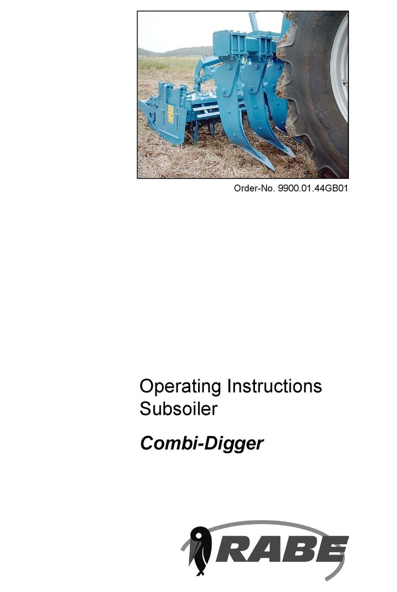
Rabe Combi-Digger Series User manual