GE WavePro LVPCB User guide

WaveProTM Low Voltage Power Circuit Breakers
Application Guide
The Ultimate Assurance
In Uptime And Reliability
Now with 100kAIC ratings!

WaveProTM Low Voltage Power Circuit Breakers
Table Of Contents
Key Features . . . . . . . . . . . . . . . . . . . . . . . . . . . . . . . . . . . . . . . . . . . . . . . . . . . . . . . . . . . . . . . . . . . . . . . . . . . . . . . . .2
Basic Configurations & Ratings . . . . . . . . . . . . . . . . . . . . . . . . . . . . . . . . . . . . . . . . . . . . . . . . . . . . . . . . . . . . . . . . . .3
Features & Characteristics . . . . . . . . . . . . . . . . . . . . . . . . . . . . . . . . . . . . . . . . . . . . . . . . . . . . . . . . . . . . . . . . . . . . . .4
Operation . . . . . . . . . . . . . . . . . . . . . . . . . . . . . . . . . . . . . . . . . . . . . . . . . . . . . . . . . . . . . . . . . . . . . . . . . . . . . . . . . . .6
Accessories for Drawout Breakers . . . . . . . . . . . . . . . . . . . . . . . . . . . . . . . . . . . . . . . . . . . . . . . . . . . . . . . . . . . . . . . .7
Trip Units — Power+™ . . . . . . . . . . . . . . . . . . . . . . . . . . . . . . . . . . . . . . . . . . . . . . . . . . . . . . . . . . . . . . . . . . . . . . .12
Trip Characteristics — Power+™ . . . . . . . . . . . . . . . . . . . . . . . . . . . . . . . . . . . . . . . . . . . . . . . . . . . . . . . . . . . . . . . .14
Trip Units — MicroVersaTrip Plus™ and PM™ . . . . . . . . . . . . . . . . . . . . . . . . . . . . . . . . . . . . . . . . . . . . . . . . . . . .17
Trip Units — MicroVersaTrip Plus™ . . . . . . . . . . . . . . . . . . . . . . . . . . . . . . . . . . . . . . . . . . . . . . . . . . . . . . . . . . . . .18
Trip Characteristics — MicroVersaTrip Plus™ and PM™ . . . . . . . . . . . . . . . . . . . . . . . . . . . . . . . . . . . . . . . . . . . .19
Trip Characteristics — Power+, MicroVersaTrip Plus™ and PM™ . . . . . . . . . . . . . . . . . . . . . . . . . . . . . . . . . . . .21
Trip Units — MicroVersaTrip PM™ . . . . . . . . . . . . . . . . . . . . . . . . . . . . . . . . . . . . . . . . . . . . . . . . . . . . . . . . . . . . .23
MicroVersaTrip PM™ Metering and Relaying . . . . . . . . . . . . . . . . . . . . . . . . . . . . . . . . . . . . . . . . . . . . . . . . . . . . .24
Trip Unit and Rating Plug Catalog Numbers . . . . . . . . . . . . . . . . . . . . . . . . . . . . . . . . . . . . . . . . . . . . . . . . . . . . . .27
WavePro™ Breaker Catalog Number Guide . . . . . . . . . . . . . . . . . . . . . . . . . . . . . . . . . . . . . . . . . . . . . . . . . . . . . .28
WavePro™ Breaker Wiring Diagram . . . . . . . . . . . . . . . . . . . . . . . . . . . . . . . . . . . . . . . . . . . . . . . . . . . . . . . . . . . . .30
Breaker Weights and Fuse Ratings . . . . . . . . . . . . . . . . . . . . . . . . . . . . . . . . . . . . . . . . . . . . . . . . . . . . . . . . . . . . . . .32
Time Current Curves . . . . . . . . . . . . . . . . . . . . . . . . . . . . . . . . . . . . . . . . . . . . . . . . . . . . . . . . . . . . . . . . . . . . . . . . .34
Standards & Testing . . . . . . . . . . . . . . . . . . . . . . . . . . . . . . . . . . . . . . . . . . . . . . . . . . . . . . . . . . . . . . . . . . . . . . . . . .37
Guideform Specifications . . . . . . . . . . . . . . . . . . . . . . . . . . . . . . . . . . . . . . . . . . . . . . . . . . . . . . . . . . . . . . . . . . . . . .39

1
WaveProTM Low Voltage Power Circuit Breakers
WavePro circuit breakers are the newest generation of GE
low voltage power circuit breakers. WavePro builds on the
experience of the AKR breaker line to bring new conve-
nience and safety features while retaining the robustness of
GE’s long-standing power circuit breaker products. WavePro
breakers are ANSI designed and carry the UL label. They
are designed to withstand short circuit stresses equal to their
short time interrupting ratings. This means that maximum
selectivity with downstream devices can be attained because
instantaneous trips are not required to achieve the breaker’s
short circuit rating. This attests to the ruggedness of the
WavePro design and places it ahead of insulated case
breakers and other maker’s power circuit breakers in many
critical applications. WavePro breakers can be applied on
power systems from 208 to 600 volts and have current ratings
of 800 through 5000 amperes. Short circuit interrupting
ratings for WavePro breakers range from 30kA to 200kA
rms symmetrical.
Why Specify Low Voltage Power Circuit Breakers?
All circuit breakers perform the function of basic circuit
protection. What separates low voltage power circuit break-
ers (LVPCB) from insulated case (ICCB) and molded case
(MCCB) circuit breakers are features and ratings that make
the equipment application safer to operate, easier to main-
tain, and maximize equipment uptime. Some of the key dif-
ferences are:
LVPCB ICCB/MCCB
Maximum ambient 40°C equipment ambient 25°C equipment ambient
operating temperature (55°C breaker ambient) (40°C breaker ambient)
Nominal/Maximum 240/254v 240/240v
operating voltage 480/508v 480/480v
600/635v 600/600v
Short circuit testing 30 cycles @ 15% PF 3 cycles @ 20% PF
(Instantaneous trips not required
for interrupting rating)
Switchgear/Switchboard Drawout (closed door) Drawout (not closed door)
mounting or Stationary
Greater Convenience And Operational Safety
General Electric pioneered the closed door drawout design
for low voltage power circuit breakers with the AK line of
breakers. WavePro retains that safety feature and adds more
features. Control, status and circuit information are all
available on the front of the breaker with the breaker
compartment door closed. All breakers have a flush-mounted
handle for charging the closing springs. Operation of the
breaker can be accomplished through manual OPEN/
CLOSE buttons on the escutcheon. The escutcheon also
includes indicators for closing spring status, main contact
status, and breaker drawout position. Trip units are mounted
behind a sealable cover for easy viewing of the display and
access to the rating plug test receptacle. When equipped
with a bell alarm, the target/reset button is also mounted in
the escutcheon. The charging handle and the close and open
push buttons are double insulated from live components to
provide additional operator safety. A standard padlock device
allows you to install up to three padlocks to prevent acciden-
tal or unauthorized closing of the breaker.
Field Installable Accessories
WavePro breakers feature standardized wiring to dedicated
secondary disconnect points for all accessories. This allows
you to easily add accessories to the breaker should it
become necessary after the breaker is installed. Field
installable accessories include auxiliary switch, shunt trip,
undervoltage device, electrical lockout device, bell alarm
with or without lockout, “hidden-on” button, close and trip
push button covers, remote close accessory, remote charge
indicator and operations counter. Trip units can be upgraded
easily and the breakers can be made “power management
ready” so that stepping up to the top-of-the-line MicroVersaTrip
PM trip unit is as easy as replacing the trip unit — no
additional modifications to the breaker are required.
Three Choices Of Advanced, Solid-State Trip Units
For basic functionality, the Power+™ trip unit gives you
straightforward means of providing overload and short
circuit protection on a WavePro circuit breaker. Tripping
characteristics are easily adjusted by simple-to-use rotary
switches. The trip unit is upgradeable to ground fault by
simply inserting a ground fault rating plug. An optional
target module allows for target monitoring and also functions
as a trip unit health indicator. Enhanced MicroVersaTrip
Plus™ and MicroVersaTrip PM™ trip units give you two ways
to monitor and control the WavePro breaker with unprece-
dented ease. A simple keypad lets you program and display a
variety of functions including tripping characteristics, remote
communications, status information and protective relaying,
and allows integration with GE POWER LEADER™ Power
Management Systems. The trip unit display also allows view-
ing of many standard metering parameters as well as pickup
alarms, trip target indications and fault status information.

2
Key Features
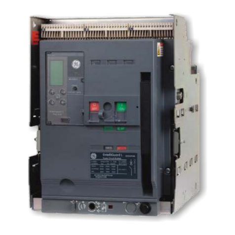
1. Padlock provision on the breaker escutcheon to
lock the breaker in the open and trip-free position
2. Optional operations counter (field installable)
3. Trip unit visible through the breaker escutcheon
— metering and trip information accessible
without opening the cubicle door
4. Choice of three trip units — Power+™, MicroVersaTrip
Plus™ or MicroVersaTrip PM™
5. Power Management Ready — breaker can be pre-wired
for power management trip unit (MVT-PM) —
upgrading is as simple as changing the trip unit
6. Flush mounted manual charging handle provided
on both manually operated and electrically operated
breakers
7. Field-installable accessories — shunt trip, bell alarm
(shown), auxiliary switch, undervoltage device,
electrical lockout device, “hidden-on” (limited
access) button, secondary disconnect(s), remote
close accessory, CLOSE and TRIP push button covers
(sealable), remote charge indicator switch
8. Sealable door over the trip unit — trip settings can be
viewed but not changed
9. Easy access to key breaker operating information —
drawout position indicator, breaker contact status, closing
spring status all visible from the front of the breaker
10. Manual close button (“limited access” option on
electrically operated breakers)
11. Dedicated secondary disconnect points — up to 72
connection points available to accommodate all breaker
accessories, including power management and neutral
sensor (see breaker wiring diagram on pages 30 and 31)
12. Expanded auxiliary switch option — 4 stage or 7 stage
13. “One-shot” electronic close circuit (not shown)
14. Breaker rating nameplate with 15 digit catalog number.
Catalog number completely describes breaker ratings,
trip unit type and characteristics, breaker operation
and control voltages, and all accessories with associated
ratings.
5
2
1
6
7
8
9
10
12
11
3, 4, 5
14

3
Basic Configurations & Ratings
WPS — Standard IC
WPH — High IC
WPX — Extended IC
WPF — Integrally fused (200kA IC)
WavePro 800-2000A Frame
WavePro 3200-4000A Frame
Short-Circuit Ratings
Rated AC RMS Symmetrical kA
Voltage, Frame With Without
Nominal Breaker Size Short-Time
Instantaneous Instantaneous
(max) Type (amps) Withstand Trip Trip
WPS-08 800 30 30 30
WPH-08 800 42 42 42
WPX-08 800 50 50 50
600 WPS-16 1600 42 42 42
WPH-16 1600 65 65 65
(635) WPS-20 2000 65 65 65
WPS-32 3200 65 65 65
WPH-32 3200 85 85 85
WPX-32 3200 85 85 85
WPS-40 4000 85 85 85
WPX-40 4000 85 85 85
WPS-50 5000 85 85 85
WPX-50 5000 85 85 85
WPS-08 800 30 30 30
WPH-08 800 42 42 42
WPX-08 800 65 65 65
480 WPS-16 1600 50 50 50
WPH-16 1600 65 65 65
(508) WPS-20 2000 65 65 65
WPS-32 3200 65 65 65
WPH-32 3200 85 85 85
WPX-32 3200 100 100 100
WPS-40 4000 85 85 85
WPX-40 4000 100 100 100
WPS-50 5000 85 85 85
WPX-50 5000 100 100 100
WPS-08 800 30 42 30
WPH-08 800 42 50 42
WPX-08 800 65 65 65
240 WPS-16 1600 50 65 50
WPH-16 1600 65 65 65
(254) WPS-20 2000 65 65 65
WPS-32 3200 65 85 65
WPH-32 3200 85 130 85
WPX-32 3200 100 130 100
WPS-40 4000 85 130 85
WPX-40 4000 100 130 100
WPS-50 5000 85 130 85
WPX-50 5000 100 130 100
Basic Configurations
WavePro™ low voltage power circuit breakers are available
in various levels of interrupting capacity (IC) and are
identified with a suffix in the model number. WPS indicates
“standard IC”, WPH indicates “high IC”, WPX indicates
“extended IC” and WPF indicates “integrally fused”.
High IC and extended IC breakers are used with larger
kVA substation transformers as well as in parallelling appli-
cations. Fused circuit breakers take the IC rating to 200kA
rms symmetrical for the highest short circuit applications.
Refer to Table 3.1 for the interrupting capacity (IC) of
WavePro breakers at system operating voltages.
Refer to Table 32.2 for available fuse ratings.
Table 3.1 WavePro Breaker Interrupting Ratings

4
Features & Characteristics
Drawout Construction
All WavePro breakers are furnished in drawout construction.
They may be used in type WPxxxSUBxxx substructures
or mounted in type AKD-10 low voltage switchgear and
PBII/AV3 ACCESS low voltage switchboards. The OEM
substructure uses many of the same components as the
AKD-10 breaker cubicles and hence share many of the
convenience and safety features inherent in drawout breaker
construction. Drawout construction permits activation of
a new feeder, rapid circuit breaker replacement, and/or
inspection and maintenance of a breaker without the
inconvenience of de-energizing the entire switchgear lineup.
Features (see photos, following page)
1. Interlocks: Standard interlocks include: (A) a drawout
interlock which prevents the breaker from being closed
unless it is in the TEST or CONNECT position, (B) a
contact interlock which prevents moving the drawout
breaker unless the main contacts are open — access to the
drawout mechanism racking screw is prevented when the
breaker is closed, (C, not shown) a spring discharge interlock
that automatically discharges the closing springs when the
breaker is moved from the TEST to the DISCONNECT
position — this prevents withdrawing a breaker from the
cubicle with the closing springs charged.
2. Secondary disconnects: Up to 72 secondary disconnect points
are available on all breakers. Control circuits and accessories
have dedicated points on the disconnects which allows
standardized wiring to the breaker and the ability to add
accessories at a later date without modifying the breaker
or cubicle wiring. Breaker mounted secondary disconnects
engage mating disconnects in the breaker cubicle when
the breaker is in the TEST or CONNECT positions only.
3. Breaker Status Indicators: A breaker contact status indicator
shows the position of the main contacts OPEN or CLOSED.
The status of the closing springs is indicated as CHARGED
or DISCHARGED. The drawout position indicator displays
whether the breaker is in the CONNECT, TEST or DISCON-
NECT position. The breaker also includes a switch that pro-
vides main contact status indication to the POWER
LEADER™ Power Management System.
4. Rejection feature: A built-in rejection feature prevents inser-
tion of a breaker into an incorrect cubicle or substructure.
This prevents either: insertion of a breaker with a lower
interrupting capability (IC) into a high IC cubicle or
substructure, or insertion of a higher ampere rated breaker
into a lower ampere rated cubicle or substructure, or both.
Within a given frame size, a higher IC breaker will be
allowed into a lower IC cubicle or substructure (ex. a
WPX-08 breaker would be able to rack into a WPH-08
or WPS-08 cubicle or substructure). Fused breakers are
rejected from all other cubicles or substructures.
5. Padlocking devices: (A) Supplied on all breakers, the
padlocking device allows up to three padlocks —
1⁄4
” to
3⁄8
”
diameter shank — to be installed to keep the breaker
mechanically trip-free. (B) A drawout padlock provision
on the side of all breakers permits locking the breaker in
either the TEST or DISCONNECT position with up to three
padlocks. (C) Furthermore, the rails in the substructure and
breaker cubicle will accept up to three padlocks to prevent
insertion of a breaker into an empty cubicle.
6. Key Interlock: Optional provisions for a key interlock
are located on the left side of the substructure or cubicle.
Key interlocks are used to supervise the closing of a circuit
breaker or the operation of upstream or downstream devices.
Typical applications include interlocking main and tie break-
ers to prevent paralleling and interlocking secondary main
breakers with primary air switches. Up to two key positions
can be accommodated on each cubicle or substructure.
7. Drawout mechanism: A front accessible racking shaft is used
to move the breaker through the various drawout positions.
The racking shaft is located in the escutcheon on WP-08,
WP-16 and WP-20 breakers. It is located on the right side of
WP-32, WP-40 and WP-50 breakers and is accessed through
a covered opening in the cubicle door.
8. Substructure: The substructure is a self-contained framework
serving as a stationary receptacle for the WavePro drawout
breaker. The substructure is designed for convenient mount-
ing, with holes provided for bolting on a shelf or supports.
Holes are also provided in the primary stabs for bolting to bus
bars or terminal lugs. The substructure has retractable rails
which aid in the installation of the drawout breaker.
9. Wheels and guide bar: Allows the drawout circuit breaker to
ride on the cubicle or substructure’s retractable rails for easy,
precise removal and installation.
10. Shutters: Shutters are available as an optional accessory
to protect personnel from inadvertently touching the primary
stabs of an energized cubicle or substructure when the
drawout breaker unit is removed.
11. Position Switch:
(By-pass switch or TOC truck-operated-con-
tact) This accessory is available with either two NO and two NC
or six NO and six NC electrically separate contacts. The switch
changes state when the breaker is racked from the CONNECT
to the TEST position. The position switch is used to indicate
the drawout position of the breaker, enable/disable control
circuits, and/or bypass auxiliary contacts when the breaker
is in the TEST/DISCONNECT/WITHDRAWN positions.
12. Lifting tool: Lifting tools are provided with each line-up
of drawout switchgear and are available as accessories for
substructures, and should be used to assist in safe handling
of the drawout breaker. The lifting tool for 800-2000A frame
breakers features 3 point lifting for easier installation of fused
and unfused breakers. Separate lifting tools are used for 3200-
4000A breakers and for 5000A breakers.
5
Features & Characteristics (cont.)
2
1A
9
3
1B
7
5A
12
6
11
10
8
9
4
5C

Operation
6
Description of Operation
Manually operated — All manually operated breakers are
charged via the pump handle in the escutcheon. Operating
the charging handle several times fully charges the closing
springs. A flag in the
escutcheon will indicate
the springs are
CHARGED and the
charging handle will
free-wheel. The breaker
is now ready to be closed
by pressing the CLOSE
button in the
escutcheon. All breakers
have a charge-after-close
feature that allows the
closing springs to be
recharged after closing.
This permits a
charge/close/recharge/trip/close/trip sequence of opera-
tion. The breaker opening springs are automatically
charged when the breaker is closed. The breaker may be
opened by pressing the OPEN button.
Electrically operated — All electrically operated breakers
are provided with a spring charging motor, manual charg-
ing handle, electronic closing circuit with anti-pump feature
and a shunt trip. Upon application of control power to the
breaker (secondary disconnect A8 & A17), the closing
springs will charge. Power to the spring charging motor is
removed automatically by a cutoff switch when the springs
are fully charged and the breaker is ready to operate.
Closing can be accomplished by pressing the manual
CLOSE button in the escutcheon (if so equipped) or by
applying voltage to the closing circuit (secondary disconnect
A9 & A18). The closing springs will automatically recharge
after the breaker is closed. The spring charging circuit is
wired separately from the closing circuit so that a separate
source can be used for spring charging as well as providing
the ability to block automatic recharging of the springs if
required by the breaker application. The anti-pump feature
in the closing circuit provides one closing operation of the
breaker for each application of a close signal — a main-
tained close signal on the breaker will produce only one
close operation and the close signal must be removed and
reapplied to reclose the breaker. Mechanical interlocks pre-
vent closing the breaker with partially charged springs and
also prevent the closing springs from discharging if an
attempt is made to close a beaker which is already closed.
Electrically operated breakers are provided with a manual
CLOSE button in the escutcheon. If local manual closing is
not required, the breaker can be equipped with a “HIDDEN
ON” feature that
replaces the CLOSE
button with a limit-
ed access cover — a
0.100” rod is
required to manual-
ly close the breaker.
The manual charg-
ing
handle built into the
escutcheon can be
used to charge the
closing springs in
the event control
power is not avail-
able or is interrupt-
ed during the spring
charging cycle. Opening of the circuit breaker is accom-
plished by pressing the OPEN button or by energizing the
shunt trip coil.
Sequence of operation
OPEN/CLOSED Main Breaker Charge Condition of Next Permissible
Indicator Contacts Indicator Charging Springs Operating Function
OPEN Open DISCHARGED Discharged Mechanism may be charged
OPEN Open CHARGED Fully Charged Breaker may be closed
CLOSED Closed DISCHARGED Discharged Mechanism may be recharged or
Breaker may be opened
CLOSED Closed CHARGED Fully Charged Breaker may be opened
OPEN Open CHARGED Fully Charged Breaker may be closed or mechanism
may be discharged without closing
contacts by holding the OPEN button
depressed while pushing CLOSE button

7
Accessories for Drawout Breakers
Auxiliary Switch (Field installable kit available)
The auxiliary switch is used for indication of breaker main
contact position. It is available on manually and electrically
operated breakers in either
a 4-stage or 7-stage config-
uration. The 4-stage switch
yields 3NO and 3NC con-
tacts while the 7-stage
switch yields 6NO and 6NC
contacts. Normally open
(NO) contacts follow the
breaker primary contact position while normally closed
(NC) contacts operate opposite the breaker primary con-
tacts. All auxiliary switch contacts feature rugged double-
break construction. Refer to breaker wiring diagram
10057403P1 for contact configurations and secondary dis-
connect terminations. Ratings of the auxiliary switch con-
tacts are shown in Table 7.1.
Table 7.1 Auxiliary switch ratings and contact operation
Table 7.2
Table 7.3
Bell Alarm with/without Lockout (Field installable kit available)
The bell alarm device is provided with two C-form contacts
— each C-form contact is
1NO and 1NC contact with
a common connection. The
bell alarm device operates
whenever the breaker trips
due to a protective function
of the trip unit. It can be
used to provide remote indi-
Field installable auxiliary switch kit catalog numbers
Auxiliary switch WP-08 / 16 / 20 WP-32 / 40 WP-50
Four stage WPAUXSF4STG WPAUXLF4STG WPAUXXF4STG
Seven stage WPAUXSF7STG WPAUXLF7STG WPAUXXF7STG
Auxiliary switch contact operation
Breaker primary contacts “a”-contact (NO) “b”-contact (NC)
Open or tripped Open Closed
Closed Closed Open
Auxiliary Switch Ratings ①
Rating (Amperes)
Control Voltage Non-inductive Inductive
24 15 10
DC 125 10 5
250 5 5
AC - 60Hz 120 15 15
240 10 10
①20A continuous rating of switch limited to 15A continuous
rating of #16AWG wire on drawout breakers
cation of a fault trip and/or disable electrical operation of
breakers that may have automatic control.
For Power+™ and MicroVersaTrip Plus™ trip units, the bell
alarm will operate for overload, short circuit and ground
fault trips. For MicroVersaTrip PM™ trip units, the bell
alarm will operate for the same overcurrent trips plus any
of the
protective relay trips that are enabled in the trip unit.
Tripping via the manual trip button, shunt trip, undervoltage
device or open fuse lockout will not operate the bell alarm.
The bell alarm can be furnished with a mechanical lockout
feature that will prevent the breaker from being manually
closed until the lockout is reset. Reset of the contacts and lock-
out feature is accomplished by pushing the yellow “reset” but-
ton on the breaker escutcheon. The reset button also serves as
a target indicator that the bell alarm has been operated.
Ratings of the bell alarm contacts are shown in Table 7.4.
Table 7.4 Bell alarm contact ratings
Table 7.5
Electrical Lockout (Field installable kit available)
The electrical lockout device provides a means to electrically
enable or disable manual closing of a circuit breaker. This
device must be energized prior to attempting to manually
close the breaker. Once the breaker is closed, loss of voltage
will not trip the breaker. A manual bypass interlock is pro-
vided for initial startup. Refer to the undervoltage device for
ratings and coil characteristics. (Note: Interlocking of elec-
trically operated breakers does not require an electrical
lockout device.)
Table 7.6
Field installable electrical lockout kit catalog numbers
Control voltage WP-08 / 16 / 20 WP-32 / 40 / 50
120Vac 50/60Hz WPELSF56120 WPELLF56120
240 Vac 50/60Hz WPELSF56240 WPELLF56240
24Vdc WPELSFDC024 WPELLFDC024
48Vdc WPELSFDC048 WPELLFDC048
110Vdc WPELSFDC110 WPELLFDC110
125Vdc WPELSFDC125 WPELLFDC125
250Vdc WPELSFDC250 WPELLFDC250
Field installable bell alarm kit catalog numbers
(Kit provides choice of with or without lockout)
WP-08 / 16 / 20 WP-32 / 40 / 50
WPBASF WPBALF
Bell Alarm Contact Ratings
AC Ratings DC Ratings
6A @ 240Vac 0.5A @ 125Vdc
0.25A @ 250Vdc

Fans and Fan Controller (WP-50)
The WP-50 breaker is provided with integrally mounted
cooling fans. Fan control is initiated by the trip unit which
signals a fan controller to turn the fans on and off when the
load current exceeds or drops below 4200 amperes. The fan
motors require 120Vac and the fan controller requires
24Vdc auxiliary power. Both the fans and the fan controller
are wired to the breaker secondary disconnect. The 24Vdc
source can be the POWER LEADER™ power supply used for
MicroVersaTrip PM™ trip units. 120Vac is normally provided
by the switchgear control power transformer. Power require-
ment for each fan is 0.2amps @ 120Vac (two fans installed).
Hidden-On Button and Push Button Covers
(Field installable kit available)
All electrically operated WavePro breakers are
provided with a manual close button on the
escutcheon. For applications where manual
closing is not desirable, the Hidden-On close
button can replace the standard manual close button. This
feature provides limited access to the mechanical close
mechanism. For emergency or supervised operation, a
0.100” diameter rod can be inserted through a hole in the
Hidden-On button to manually close the breaker. The
Hidden-On feature provides double insulation between the
operator and any live parts in the breaker. This feature is typ-
ically used on a breaker that is electrically interlocked with
other breakers, such as in an automatic transfer scheme.
Sealable covers can be provided for the CLOSE and OPEN
buttons on the breaker escutcheon. These covers help pre-
vent accidental manual operation of the circuit breaker.
Applications include supply breakers for fire pumps (to pre-
vent access to the OPEN button) or critical feeders where
accidental operation may have a serious impact on a
process. The push button covers can be applied to either
the CLOSE or OPEN buttons or both.
Table 8.1 Field installable kit catalog numbers
Lifting Tool
The lifting tool is the interface between
the breaker and the overhead breaker
lifting device or any other portable lift-
ing means that may be used for
installing and removing the WavePro draw-
out breakers. It attaches to the breaker to
provide stability when lifting the breaker from its drawout
rails. Pickup points on the breaker and lifting tool are
WP-08 / 16 / 20 / 32 / 40 / 50
Hidden-On Button Sealable Push Button Covers (Qty 2)
WPHIDONKIT1 WPPBCVRKIT2
designed for center-of-gravity lifting so that the breaker is not
subject to excess movement when removed from the cubicle.
Table 8.2
WavePro Breaker Lifting Tools
OEM Substructure
All WavePro drawout circuit breakers are
integrated into switchgear or switchboard
equipment by way of a substructure. The
substructure includes the drawout rails, pri-
mary disconnects, and breaker rating rejec-
tion plate. Options for the substructure include shutters,
secondary disconnects, key interlocks, position switch, cur-
rent transformers, door interlock, and rail padlocking. For
detailed information (catalog numbers, dimensions, installa-
tion instructions) on substructures and accessories for OEM
applications, refer to the OEM handbook, DEB-011A Volume 3.
Open Fuse Lockout (OFLO)
The open fuse lockout device is provided
with any fused breaker. The OFLO consists
of an individual trip solenoid for each pole,
connected directly across the fuse in that phase. When any
fuse blows, the solenoid is energized and trips the breaker to
prevent single-phasing. The breaker is mechanically locked
out and cannot be reclosed until the fuse is replaced and the
target indicator of the phase involved is reset.
When the fuses are mounted in a
separate fuse roll-out (used with
WPS-20, WPS-32, WPS-40, WPS-50)
the open fuse lockout is wired to
the fuses through secondary discon-
nects on the rollout and on the
breaker. The OFLO utilizes dedicated secondary disconnect
points, so no other breaker accessories are affected.
Operations Counter
(Field installable kit available)
The operations counter
mounts on the breaker
as a five-digit, non-resettable
counter actuated by the
breaker closing mechanism.
Table 8.3
Field Installable Operations Counter kit catalog numbers
WP-08 / 16 / 20 WP-32 / 40 / 50
WPCTRSFKIT1 WPCTRLFKIT1
Fuse Roll-out Fuse Roll-out
WP-08 / 16 / 20 WP-32 / 40 WP-50 2000 / 3200 / 4000A 5000A
Lifting 0324B4551G001 0247B8961G001 0247B8961G003 0247B8961G004 0247B8961G005
Tool
8
Accessories for Drawout Breakers (cont.)

9
Accessories for Drawout Breakers (cont.)
Padlocking Provisions
All WavePro breakers are furnished with
standard padlocking provisions for opera-
tor safety. The breaker may be placed in a
“trip-free” position by utilizing the padlock
provision on the breaker escutcheon which
holds the OPEN button depressed. This
padlocking feature holds up to three locks.
The breaker may also be padlocked in the
TEST or DISCONNECT position. When in
either of these positions, the breaker lines
up with padlocking provisions in the com-
partment or on the drawout rails and will
accept up to three padlocks to secure the breaker in either
the TEST or DISCONNECT position.
“PM-Ready”
In its most basic form, a manually operated WavePro break-
er, with a Power+™ or MicroVersaTrip Plus™ trip unit and
no other accessories, may be able to be supplied without
secondary disconnect points. The “PM-Ready” option equips
the breaker with a secondary disconnect and inputs for
24Vdc auxiliary power, communications and 3-phase voltage
signals. If the breaker is already equipped with any combina-
tion of ground fault protection, zone selective interlocking,
shunt trip, auxiliary switch, bell alarm, undervoltage device,
electric lockout, or is electrically operated, the PM-ready
wiring is automatically included and does not have to be
specified. This “PM-Ready” option makes upgrading a
WavePro breaker to MicroVersaTrip PM as simple as chang-
ing the trip unit. Breaker cubicles can be equipped with the
necessary wiring to further simplify a PM-upgrade.
Racking Tool (Equipment accessory)
The racking tool is a special drive wrench with a square 1⁄2"
socket that engages the racking mechanism on the breaker.
One racking tool is used for all WavePro™ circuit breakers.
0324B4721G001 Without universal joint – all applications
except as noted below (standard)
0324B4724G001 With universal joint – must use for outdoor
applications when there is a large frame
(3200 – 5000A) breaker or fuse rollout
on the extreme right end of the line-up.
Can be used on all other breaker
applications, also.
Remote Charge Indicator Switch (Field installable kit available)
The remote charge indicator switch is a normally open dry
contact that closes when the closing springs of the breaker
are fully charged. This option is available on manually and
electrically operated breakers. The contact is rated 4.0 amps
at 120Vac and 0.5 amps at 125Vdc.
Table 9.1 Field installable Remote Charge Indicator Switch kit
catalog numbers
Remote Close Accessory with One-Shot
Electronic Close Circuit (Field installable
kit available)
The remote close accessory is an electrically
operated solenoid, which when energized,
closes the breaker. It is suitable for control interlock schemes
in which manual closing capability would not be convenient
or would be too slow. It is an optional accessory for a manual-
ly operated breaker but is always supplied with electrically
operated breakers. The remote close accessory consists of the
“one-shot” electronic close circuit, with built-in anti-pump
feature, and the closing solenoid. The remote close accessory
is continuously rated and operates as follows.
Applying control voltage to the close circuit produces a
250msec pulse to the closing coil which in turn releases the
energy stored in the closing springs. The anti-pump feature
prevents the breaker from repeatedly closing if the close sig-
nal is maintained. A momentary close signal (1⁄2second dura-
tion) is sufficient to close the breaker but if the close signal is
maintained while the breaker is closed, the signal must be
removed and then reapplied in order to reclose the breaker.
Reset time for the anti-pump circuit is approximately 2.5 sec-
onds. For applications requiring rapid reclosure of a circuit
breaker, a momentary close signal should be used. This
allows the anti-pump circuit to reset while the closing springs
are recharging and the breaker is then ready to reclose with-
out any additional time delays. A close signal applied to a
closed breaker will provide a pulse to the close coil but the
closing mechanism is mechanically blocked thereby prevent-
ing the closing springs from discharging. The close signal
must be removed as stated above before the breaker can be
reclosed. Control power requirements for electrically charg-
ing and closing the breaker are shown in Tables 9.2 and 10.1.
Table 9.2 WP-08 / 16 / 20 circuit breakers
Spring charging Closing
motor (amps) coil
Nominal Charge / Charging
control Voltage inrush close fuse time
voltage range Inrush Sustained (amps) (amps) (sec)
120v-60Hz 104-127 25.0 5.0 16.0 15 0.9
120v-50Hz 104-127 25.0 5.0 16.0 15 0.9
240v-60Hz 208-254 12.0 3.0 7.0 15 0.9
240v-50Hz 208-254 12.0 3.0 7.0 15 0.9
48Vdc 38-56 40.0 10.0 15.0 15 1.5
110/125Vdc 100-140 27.0 5.0 4.0 15 1.0
250Vdc 200-280 13.0 3.0 3.0 15 1.0
Breaker Frame and Operation
WP-08 / 16 / 20 Manually or Electrically Operated WPRCISFKIT1
WP-32 / 40 / 50 Electrically Operated WPRCILFKIT1
WP-32 / 40 / 50 Manually Operated WPRCILFKIT2

10
Accessories for Drawout Breakers (cont.)
Table 10.1 WP-32 / 40 / 50 circuit breakers
Table 10.2
Field Installable Remote Close Accessory kit catalog numbers
Secondary Disconnect (Field installable kit available)
Inputs and outputs to the circuit breaker are wired through
secondary disconnects located
on the top of the breaker. The
plug-style secondary discon-
nects engage mating discon-
nects in the breaker cubicle
when the breaker is in the
TEST or CONNECT position.
Up to 72 dedicated points are
available so that all breaker
accessories can be wired to dedicated disconnect points.
Refer to the breaker wiring diagrams shown on pages 30
and 31 for breaker accessory wiring.
Table 10.3 Field Installable Secondary Disconnect kit catalog
numbers
Shunt Trip (Field installable kit
available)
The shunt trip allows remote
electrical tripping of the circuit
breaker. It is usually controlled by
a switch or push button and may
also be used in conjunction with
protective relays for automatic
tripping (the breaker trip units do
WP-08 / 16 / 20 WP-32 / 40 / 50
Breaker side (female) WPSDSUBF1 WPSDSUBF1
Cell side (male) WPSDSUBM1 WPSDSUBM2
Control voltage WP-08 / 16 / 20 WP-32 / 40 / 50
120Vac 60Hz WPRCSF60120 WPRCLF60120
120Vac 50Hz WPRCSF50120 WPRCLF50120
240Vac 60Hz WPRCSF60240 WPRCLF60240
240Vac 50Hz WPRCSF50240 WPRCLF50240
48Vdc WPRCSFDC048 WPRCLFDC048
110Vdc WPRCSFDC110 WPRCLFDC110
125Vdc WPRCSFDC125 WPRCLFDC125
250Vdc WPRCSFDC250 WPRCLFDC250
Spring charging Closing
motor (amps) coil
Nominal Charge / Charging
control Voltage inrush close fuse time
voltage range Inrush Sustained (amps) (amps) (sec)
120v-60Hz 104-127 25.0 8.1 16.0 15 1.5
120v-50Hz 104-127 25.0 8.1 16.0 15 1.5
240v-60Hz 208-254 11.7 3.5 7.0 15 1.3
240v-50Hz 208-254 11.7 3.5 7.0 15 1.3
48Vdc 38-56 22.0 16.5 15.0 15 2.0
110/125Vdc 100-140 25.0 7.0 4.0 15 1.7
250Vdc 200-280 13.0 3.2 3.0 15 1.7
not require the use of a shunt trip). The shunt trip coil is rated
for intermittent duty and is supplied with an auxiliary switch
contact that automatically removes control power following a
breaker trip. A shunt trip is always supplied on electrically
operated breakers. A redundant or 2nd shunt trip is available
on all frame size breakers for special control applications. The
second shunt trip occupies the same space as the undervoltage
device. See Table 10.4 for shunt trip operating characteristics.
Table 10.4 Shunt trip operating characteristics
Table 10.5
Field
Installable
Shunt Trip 1 kit catalog numbers
Table 10.6
Field
Installable
Shunt Trip 2 kit catalog numbers
Spring Charging Motor
The spring charging motor is supplied on all electrically
operated breakers. The breaker closing springs are charged
automatically when control voltage is applied to the breaker.
When the springs are fully charged, a cutoff switch de-ener-
gizes the motor. The closing springs will recharge automati-
cally after the breaker closes unless an external switch con-
Control voltage WP-08 / 16 / 20 WP-32 / 40 / 50
120Vac 60Hz WPS2SF60120 WPS2LF60120
240Vac 60Hz WPS2SF60240 WPS2LF60240
24Vdc WPS2SFDC024 WPS2LFDC024
110/125Vdc WPS2SFDC125 WPS2LFDC125
250Vdc WPS2SFDC250 WPS2LFDC250
Control voltage WP-08 / 16 / 20 WP-32 / 40 / 50
70Vac 60Hz WPS1SF60070 WPS1LF60070
120Vac 60Hz WPS1SF60120 WPS1LF60120
120Vac 50Hz WPS1SF50120 WPS1LF50120
208Vac 60Hz WPS1SF60208 WPS1LF60208
208Vac 50Hz WPS1SF50208 WPS1LF50208
240Vac 60Hz WPS1SF60240 WPS1LF60240
240Vac 50Hz WPS1SF50240 WPS1LF50240
24Vdc WPS1SFDC024 WPS1LFDC024
48Vdc WPS1SFDC048 WPS1LFDC048
110/125Vdc WPS1SFDC125 WPS1LFDC125
250Vdc WPS1SFDC250 WPS1LFDC250
Nominal control Operating Inrush Sealed
voltage voltage range, V current, A current, A
70V, 60Hz 70-127 3.75 3.75
120V, 60Hz 95-127 12.3 10.8
120V, 50Hz 95-127 7.6 6.7
208V, 60Hz 165-220 3.2 2.6
208V, 50Hz 165-220 3.8 3.1
240V, 60Hz 190-254 3.9 3.4
240V, 50Hz 190-254 4.7 4.1
24Vdc 14-30 8.3 8.3
48Vdc 28-60 4.5 4.5
110/125Vdc 70-140 2.0 2.0
250Vdc 140-280 1.0 1.0

tact is wired into the spring
charging circuit. If control
power is lost during the spring
charging cycle, spring charging
can be completed using the
integral manual pump handle.
The optional remote charge indi-
cator contact can be supplied to
provide a contact closure when the springs are fully
charged. Refer to Tables 9.1 and 10.1 for spring charging
motor operating characteristics.
Test Kit
The test kit, catalog number TVRMS2, is a portable, battery-
or ac-powered unit that is used for trip unit health checks
and also provides functional
trip and no-trip tests of the
trip unit. It can be used to
defeat the ground fault func-
tion of the trip unit when
performing high current
tests on the circuit breaker.
The test kit supplies 24Vdc
auxiliary power for cold set-
up and viewing of trip targets
on trip units not equipped with on-board batteries. The dis-
play on the test kit can be used to verify pickup and delay
settings that have been programmed into the trip unit. This
test kit is designed for use with all Power+™ , MicroVersaTrip
Plus™
and MicroVersaTrip PM™ trip units.
Undervoltage Device (Field installable kit available)
The undervoltage device protects against harmful drops or
complete loss of voltage by automatically tripping the break-
er. The undervoltage device can be used to sense the drop
or loss of bus voltage through the use of voltage transform-
ers or it can monitor a control voltage source. This device is
set to pick-up at approximately 85% of rated voltage and
will drop out instantaneously between 30 and 60% (nonad-
justable) of rated voltage. An electronic module on the
undervoltage device provides accurate and repeatable oper-
ating characteristics. The
undervoltage device is avail-
able with an optional static
time delay unit. This unit
offers a field-adjustable two- to
six-second delay between
undervoltage occurrence and
breaker trip, thus preventing
potential nuisance tripping
due to momentary loss of volt-
age. The time delay unit is
11
Accessories for Drawout Breakers (cont.)
mounted externally to the breaker. It is rated 125Vdc,
250Vdc, 208Vac or 240Vac, 50/60Hz. For any other AC
source voltage, a control power transformer with a 240v sec-
ondary, rated at least 100VA, is required. Refer to Table 11.1
for undervoltage device operating characteristics.
Table 11.1 Undervoltage device operating characteristics
Table 11.2
Field
Installable
Undervoltage Device kit catalog numbers
Table 11.3
Field Installable Time Delay Undervoltage Device kit catalog
numbers (order Static Time Delay Unit separately)
Table 11.4 Static Time Delay catalog numbers
Zone Selective Interlocking (Optional)
Zone selective interlocking is available for either ground
fault only, or both ground-fault and short-time functions.
The zone selective interlocking feature requires a zone
selective interlock module (ZSIM) catalog number TIM1.
The module is an intermediate control device used between
upstream and downstream circuit breakers to communicate
with the short-time and ground-fault zone selective interlock
functions of the MicroVersaTrip Plus and MicroVersaTrip
PM units. The module requires 120/208/240 Vac, 15 VA
maximum. Refer to page 22 for more details.
Nominal Control Voltage Catalog Number
125Vdc TAKYUVT-1
250Vdc TAKYUVT-2
240Vac TAKYUVT-4
208Vac TAKYUVT-5
Control voltage WP-08 / 16 / 20 WP-32 / 40 / 50
208/240Vac 50/60Hz WPUVSFTD240 WPUVLFTD240
125Vdc WPUVSFTD125 WPUVLFTD125
250Vdc WPUVSFTD250 WPUVLFTD250
Control voltage WP-08 / 16 / 20 WP-32 / 40 / 50
120Vac 50/60Hz WPUVSF56120 WPUVLF56120
240Vac 50/60Hz WPUVSF56240 WPUVLF56240
24Vdc WPUVSFDC024 WPUVLFDC024
48Vdc WPUVSFDC048 WPUVLFDC048
110Vdc WPUVSFDC110 WPUVLFDC110
125Vdc WPUVSFDC125 WPUVLFDC125
250Vdc WPUVSFDC250 WPUVLFDC250
Nominal control voltage Operating voltage range Holding current, A
120Vac 0.15
240Vac Pickup at 80% of 0.07
24Vdc nominal control 0.58
48Vdc voltage, drop out at 30- 0.32
110/125Vdc 60% (non-adj) of 0.15
250Vdc nominal control voltage 0.07

12
Trip Units — Power+™
Power+™ Trip Unit Systems
The Power+ trip unit system for WavePro™ low voltage
power circuit breakers consists of the trip unit, the trip
actuator, current sensors and rating plugs. Power+ trip
units provide a complete range of standard and optional
overcurrent and ground-fault protective functions.
Components of Power+ trip unit systems
True RMS Sensing
The Power+ trip unit continues to use GE’s proven tech-
nique of measuring true rms currents of both sinusoidal
and harmonically distorted waveforms. The frequent sam-
pling (48 times per cycle per phase) allows precise calcula-
tions of true rms current. The sampling rate allows wave-
form measurements up to the 11th harmonic. GE’s true rms
sensing avoids potential underprotection or overprotection
problems associated with peak-sensing tripping systems.
Trip Target Module (Optional)
•View Button: Press the VIEW button to check the trip unit
status.
•Reset Button: Press the RESET button to clear any target
that is set.
•Battery check: Target modules use two standard, 3V, lithi-
um batteries for viewing target information. Battery life
depends upon use, but may be estimated at one year.
When the batteries are energized, depressing the VIEW
button will illuminate either a set target LED, i.e., OVL
or the BAT LED. Once target indicators are cleared, bat-
tery status is indicated by the BAT LED. Replacement
batteries include Panasonic CR1616, Eveready E-
CR1616BP, or Duracell DL1616B, which may be pur-
chased commercially.
•Long-time pickup: The long-time pickup indicator moves
through two transitions. As the current in any phase
reaches 95% of its setpoint, the LTPU LED begins to
flash. As current increases, flashing frequency increases,
until 100% of the pickup point is reached. At that
moment, the LTPU LED stays on continuously until the
long-time delay times out. Once the breaker has tripped
on long-time, the OVL target will be stored in memory.
To view the trip, press the VIEW button. To clear the tar-
get, press the RESET button.
•Short-time and instantaneous trips: Short-time and instanta-
neous trips share the same trip target. The LTPU LED is
not illuminated, since the time intervals between pickup
and tripping are too short for either function. Once the
breaker has tripped on short-time or instantaneous, the
SHORT target will be stored in memory. To view the trip,
press the VIEW button. To clear the target, press the
RESET button.
•Ground fault trip (TargetO2 only): The trip target for a
ground fault trip is the GF LED. To view the trip, press
the VIEW button. To clear the target, press the RESET
button.
•Health monitor: Trip unit health status “okay” is illustrated
by slow blinking of the LTPU LED. It may be seen by
depressing and holding the VIEW button. Sufficient
power must be supplied to the trip unit via external test
kit, power pack, or current transformers for the health
monitor to be operational.
Power+ trip target module
Table 12.1 WavePro Breaker Power+ Trip Unit Target Module
Power+ Trip Unit Suffix Power+ Target Module Catalog Number
(none) TARGET00 (blank)
T1 TARGET01 (w/0 GF)
T2 TARGET02 (with GF)

Trip Units — Power+™ (cont.)
13
Operation of Power+™ Trip Units
Block diagram of Power+ trip unit
Power+ trip units have a variety of standard and optional
functions. The block diagram shows a fully configured
Power+ trip unit with ground-fault protection. The current
sensors are special current transformers that provide the
trip unit with its operating power. Interchangeable rating
plugs act as scalars for the outputs of the current sensors, as
well as establish the current rating of individual breakers.
When a four-wire system is used and ground fault protection
is called for, an external neutral sensor is necessary.
Analog current signals are converted to digital values, and
are measured and compared with established trip settings in
the microprocessor’s memory. Any overcurrent or ground
fault condition that exceeds preset conditions produces a
A B C N
Phases
A B C N
Phases
Currents
Phase
Optional
Neutral Current
Rating
Plug
Fault
(Opt)
Ground
Breaker Mounted
Current Sensors
Auxiliary Contact
(Microswitch)
Target
Module
(Optional)
Bell Alarm
with or w/o
Lockout
A/D Converter
Fault
Fault
Trip Logic
Power+
Trip Unit
Trip Actuator
trip signal from the microprocessor to the trip actuator. The
trip actuator is a low energy, positive-action tripping device.
The low-level trip signal counteracts the strength of the
actuator’s permanent magnet, and allows a spring to unseal
the magnet and trip the breaker.
The bell alarm contacts operate only as a result of an over-
load, short circuit or ground fault trip condition.
Standard and Optional Protective Functions
Standard and optional protective functions for Power+ trip
units are shown below. The breaker settings are pro-
grammed in multiples of “X” (rating plug amp values), “S”
(current sensor amp rating values), and “C” (the long-time
setting in amps — multiply long-time setting by rating plug
amp rating).
Standard
• Adjustable Long-Time (L) Pickup, 0.5-1.1X, with four
delay bands.
• Adjustable Instantaneous (I) Pickup, up to 15X (see table
21.1 on page 21 for applicable ranges).
Options
• Overload, Short Circuit, and Ground Fault local trip indi-
cators with overload pickup warning and trip unit health
monitor.
• Adjustable Short-Time (S) Pickup, 1.5-9.0C, and delay (3
bands) with I2t IN/OUT selection.
• Adjustable Ground Fault (G) Pickup, 0.2-0.6S*, and delay
(3 bands) with I2t IN/OUT selection.
• Upgradeable Ground Fault function with use of appropri-
ate ground fault rating plug.
* Maximum ground fault setting is limited to 1200 amperes.

14
Instantaneous Function
The instantaneous trip point establishes the value of current that
will trip the breaker without intentional time delay.
Instantaneous
trip times are 50 milliseconds or less. Instantaneous trips are the
result of severe overcurrent or short-circuit conditions and dam-
age to the power system is minimized by immediate tripping.
Standard settings are adjustable in multiples of the rating plug
amp value (X). See Table 21.1 for allowable values. Maximum
setting is dependent on breaker frame size and the inclusion of a
short time function on the trip unit. Instantaneous trips are stan-
dard on WavePro breakers and can be used in conjunction with
or be replaced by the short time function. At 480 and 600 volts,
WavePro circuit breakers have the same interrupting ratings with
and without instantaneous trips. This means that the instanta-
neous trips on the breakers can be eliminated with no impact on
interrupting rating. This is beneficial when selecting the trip
characteristics of main and tie breakers, and feeders that must
coordinate with instantaneous trips downstream. There are no
“hidden” instantaneous trips on WavePro breakers when the
instantaneous function is eliminated.
Instantaneous function
Short-Time Functions (Optional)
Short-Time Pickup — The short-time pickup function controls
the level of high current the breaker will withstand for short peri-
ods of time to allow downstream devices to clear faults without
tripping the breaker. Settings are adjustable in increments of the
breaker current setting (C). See Table 21.1 for allowable values.
If the instantaneous setting is set for lower values of current than
the short-time function, the instantaneous function prevails.
Short-time pickup function
Trip Characteristics — Power+™
Long-Time Protective Functions
Long-Time Function/Current Setting (Standard)
The adjustable long-time setting is based on multiples of “X,” the
rating plug ampere rating. There are eight possible settings from
50% to 110% of rating plug amps. This setting established the
current setting of the breaker which is the current the breaker
will carry continuously without tripping. Multiplying the long-
time setting by the rating plug value establishes the value of “C.”
For example, a breaker with a 95% long-time setting and 500
amp rating plug (X) would have a 475 amp current setting, or
value of C.
Long-time current setting (C) = (0.50 to 1.10) x rating plug (X)
Long-time function, or current setting
Long-Time Delay (Standard)
Long-time delay varies the time it will take the breaker to trip
under sustained overload conditions. It permits the breaker to
ride through momentary predictable overloads (e.g., motor start-
ing) without tripping. There are four time bands that provide
nominal delays from 3 to 25 seconds at 600% of the breaker’s
current setting, or value of C.
Long-time delay
.5 .6
.7
1.1 .8
.9
.95
1.0
12
3
4
1.5 2
3
5
7
9
10
13
15
1.5 2
2.5
3
4
5
7
9

Trip Characteristics — Power+™ (cont.)
15
Once installed, the ground-fault function is enabled and
adjusted through the pickup and delay selector switches on
the rating plug. The optional Defeatable Ground Fault
includes an “OFF” setting on the ground fault delay selector
switch to allow ground fault to be temporarily disabled for
maintenance or testing purposes.
A ground-fault is an unintentional current flow from a cir-
cuit through a conductive path to ground. Ground faults
usually have intermittent or very low values of current flow,
as depicted in Graph A , and are not detected by long-time
overload protection. Some
ground-fault trip systems
may not detect this type of
fault because the intermit-
tent nature of the fault
never exceeds the trip
threshold as illustrated in
Graph B . The Power+ trip
unit detects and integrates
(adds a series of arcing and
intermittent current pulses)
the low-level current of a ground fault. This integration
function provides a memory response for ground faults to
achieve preferred ground-fault protection as shown in
Graph C .
The NEC requires that the maximum ground-fault setting
not exceed 1200 amps. Ground-fault protection includes
pickup setting, ground-fault delay settings and selectable 12t
function. Ground-fault pickup settings are based on multi-
ples of S, the current sensor rating. The lowest setting is
20% of S, and the highest setting is based on current sensor
amp ratings, such that the maximum setting does not
exceed 1200 amps. There are three ground-fault delay
bands of 1 (MIN), 2 (INT), 3 (MAX) ranging from 100 ms
to 350 ms. The I2t function adds an I2t slope to the square
corner of the ground-fault time current curve transition,
from pickup to the constant delay bands, to improve coordi-
nation with downstream devices.
Ground-fault pickup and delay
Short-Time Delay
Short-time delay is always provided when short-time pickup
is ordered. Short-time delay provides additional refinement
in providing coordination between upstream and down-
stream protective devices. There are three time delay bands
[1 (MIN), 2 (INT), 3 (MAX)] that provide delays from 100
ms to 350 ms.
Short-time delay with I2t OUT
Selectable Short-Time I2t function
Selectable short-time I2t is always provided with the short-
time option. The I2t helps the solid-state trip unit coordinate
with downstream thermal magnetic devices or fuses. This
function impacts the shape of short-time pickup and short-
time delay time current curves and may be programmed
either IN or OUT.
Short-time delay with I2t IN
Ground-Fault Protection (Optional)
Ground-Fault Protection
Power+ trip units are field upgradeable to include ground
fault protection. To upgrade to the ground-fault option,
simply remove the rating plug that does not have the
ground-fault option and install a ground-fault rating plug.
A
B
C
Ground Fault
Detection
Trip
t
t
t
Ground Fault
Detection
Ground Fault Curr ent
Ground-fault memory circuit
MIN
INT
MAX
INT
MAX
MIN
I T IN
I T OUT
2
2
I2t
OUT
MIN
INT
MAX
INT
MAX
MIN
I T IN
I T OUT
2
2
I2t
IN
(xS) .24 .26 .28
.30
.20
.22
.20
.22
I2t IN
Delay
Pickup
IN OUT
MIN MIN
INT INT
MAXMAX
I T
2I T
2

Trip Characteristics — Power+™ (cont.)
16
used with MicroVersaTrip Plus™ and MicroVersaTrip PM™
trip units. See Table 16.1 for available ratings.
Table 16.1 Breaker/Sensor/Rating Plug Combinations for Power+
Breaker Frame
Sensor Available Rating Plugs
Rating (Amps)
Rating (S) with or without Ground Fault (X)
800 150 80, 100, 125, 150
800 400 200, 225, 250, 300, 400
800/1600 800 400, 500, 600, 700, 800
1600 1600 800, 1000, 1200, 1600
2000 2000 1000, 1200, 1600, 2000
3200 3200 1200, 1600, 2400, 3200
4000 4000 1600, 2000, 2500, 3000, 4000
Power+ trip units are not available on 5000 amp (WP-50) breakers
Current Sensors
Toroidally wound current sensors are furnished for all
major protective functions for the Power+ trip unit and also
for metering if the trip unit is upgraded to MicroVersaTrip
PM — upgrading does not require changing the factory
installed current sensors. There are seven current sensor
ratings for the WavePro breaker line through 4000 amps.
See Table 16.1 above for current sensor ratings. Ratings
plugs must be coordinated with the current sensor rating
(S) listed on the face of the rating plug.
Bell Alarm
Activation of the Bell Alarm is controlled by the trip unit.
All protective function trips initiated by the trip unit will
cause the bell alarm (if so equipped) to operate. Reset of
the bell alarm contacts and the mechanical lockout (if
provided) is by way of the reset button on the breaker
escutcheon.
Rating Plugs
Power+™ trip unit rating plug
A new interchangeable rating plug is used in the Power+
trip unit across the entire WavePro circuit breaker product
line. Rating plugs are the key devices that establish the cur-
rent rating of the breaker. They provide an essential scaling
function for the unit’s microprocessor and ensure maxi-
mum accuracy. They are also used to provide ground fault
protection as well as supplying a jack for connection to an
external battery pack or the TVRMS2 trip unit test kit.
Power+ rating plugs are available in three configurations:
• No ground-fault protection
• Ground-fault protection
• Defeatable ground-fault protection (not UL)
The ground fault rating plugs have switches for ground fault
pickup and delay settings. A suffix in the rating plug catalog
number determines whether the rating plug provides
ground fault protection and if the ground fault protection
is defeatable. Refer to Table 27.3 for the appropriate rating
plug catalog number and suffix.
Rating plugs have rejection features that allow them to be
inserted only with breakers containing the correct current
sensors. Rating plugs for the Power+ trip unit cannot be

Trip Units — MicroVersaTrip Plus™ and PM™
17
The Enhanced MicroVersaTrip Plus™ And
MicroVersaTrip PM ™ Trip Unit Systems
The enhanced MicroVersaTrip Plus and MicroVersaTrip PM
trip unit systems for WavePro™ low voltage power circuit
breakers consist of the trip unit, the trip actuator, current
sensors and rating plug. The term “trip unit system” applies
to the combination of these four components which form
the circuit breaker solid-state tripping system.
MicroVersaTrip Plus trip units provide a complete range of
standard and optional overcurrent and ground-fault protec-
tive functions. MicroVersaTrip PM trip units add advanced
metering, communications and protective relaying func-
tions. MicroVersaTrip PM trip units operate with the GE
POWER LEADER™ Power Management System.
Components of MicroVersaTrip Plus unit system
True RMS Sensing
Enhanced MicroVersaTrip Plus and MicroVersaTrip PM trip
units continue to use GE’s proven technique of measuring
true rms currents (and voltages for MicroVersaTrip PM trip
units) of both sinusoidal and harmonically distorted wave-
forms. The sampling rate of 64 times per cycle per phase
allows precise calculations of true rms current and wave-
form measurements up to the 31st harmonic to achieve
accuracies of 99%. GE’s true rms sensing avoids potential
underprotection or overprotection problems associated with
peak-sensing tripping systems.
Enhancements To MicroVersaTrip Plus And MicroVersaTrip PM
Trip Units
Enhancements include several functions that simplify pro-
gramming and make fault displays easier to read and inter-
pret.
Batteries
Replaceable, long-life lithium batteries provide program-
ming and display power to the trip unit’s LCD on com-
mand. With the breaker disconnected from the source and
load, the trip unit can be removed from the breaker and all
setpoints can be defined at a technician’s desk. Caution: the
batteries are automatically shut off when no programming
operation or display request is called for within 30 seconds
after the last key is pressed. The batteries also enable the
user to read fault displays on an open breaker.
Batteries are not required to energize the trip unit display as
long as a small amount of current (20% of current sensor
rating) is flowing through the circuit breaker. The displays
of installed MicroVersaTrip PM trip units are visible at all
times due to an external 24Vdc input to the trip unit.
The batteries are not required to maintain programmed set-
tings, or to store trip information. They simply provide a
local power source to energize the trip unit when no other
source of power is available. All setpoints, time delays and
other programming functions are stored in non-volatile
memory within the trip unit’s microprocessor.
Batteries have a two year life under normal use and are user-
replaceable.
LCD
The LCD (Liquid Crystal Display) has increased contrast to
improve legibility in poor lighting conditions. International
display symbols are used for various programming functions
(e.g., “I>>” for short circuit and “I>” for overload).
Trip Operations Counter
The enhanced MicroVersaTrip Plus and MicroVersaTrip PM
trip units also store and display the total number of trips
due to long time overloads, short time and instantaneous
short circuit, and ground faults. Each display stores up to
256 operations per trip category before resetting to zero.
Each counter can be individually reset through the keypad.

18
Trip Units — MicroVersaTrip Plus™
Operation Of MicroVersaTrip Plus™ Trip Units
MicroVersaTrip Plus trip units have a menu of standard and
optional functions. The block diagram shows a fully config-
ured MicroVersaTrip Plus trip unit with ground-fault protec-
tion. The current sensors are special current transformers
that provide the trip unit with its operating power.
Interchangeable rating plugs act as scalars for the outputs of
the current sensors, as well as establish the current rating of
individual breakers. When a four-wire system is used and
ground-fault protection is called for, an external neutral
sensor is necessary.
Block diagram of MicroVersaTrip Plus trip unit
Analog current signals are converted to digital values, and
are measured and compared with established trip settings in
the micro processor’s memory. Any overcurrent or ground
fault condition that exceeds preset conditions produces a
trip signal from the micro processor to the trip actuator.
The trip actuator is a low-energy, positive-action tripping
device. The low-level trip signal counteracts the strength of
the actuator’s permanent magnet, and allows a spring to
unseal the magnet and trip the breaker.
All trip unit protective functions will operate the bell alarm
accessory (if so equipped). The two normally open and two
normally closed contacts will change state whenever the trip
actuator causes the breaker to open. The bell alarm is not
activated by any other manual or electrical tripping means.
Standard And Optional Protective Functions
Standard and optional protective functions for
MicroVersaTrip Plus trip units are shown below. The break-
er settings are programmed in multiples of “In” (rating plug
amp values),”CT”(current sensor amp rating values), and
“LT” (the long-time setting in amps-multiply long-time set-
ting by rating plug amp rating).
Standard
• 3-phase Ammeter with ±2% accuracy.
• Adjustable Long-Time (L) pickup, 0.5- 1.1In, with four
delay bands.
• Adjustable instantaneous (I) pickup, 1.5 - 9/10/13 or
15In.
• Overload and Short Circuit local trip indicators with over-
load pickup warning.
• Test set initiated trip indication.
Options
• Adjustable Short-Time (S) pickup, 1.0 - 9.0LT, and delay
(3 bands) with I2t IN/OUT selection.
• Adjustable Ground Fault (G) pickup, 0.2 - 0.6CT, and
delay (3 bands) with I2t IN/OUT selection and trip indi-
cator.
• Zone selective interlocking for Ground Fault or Ground
Fault and Short-Time.
• Defeatable Ground Fault function (non-UL).
• Switchable Short Time or Instantaneous and Ground
Fault function (non-UL).
Auxiliary Contact
(Microswitch)
MicroVersaTrip Plus
Trip Unit
24Vdc Power Supply
A/D Converter
(Optional)
Input/Output
A B C N
Phases
(Optional)
A B C N
Phases Breaker Mounted
Current Sensors
Zone Selective Interlock
Optional Neutral Current
Trip Unit Keypad
Phase
Currents Rating
Plug
Crystal
Display
with or w/o
Bell Alarm
Trip Logic
Fault
Fault
Liquid
Lockout
Trip Actuator
This manual suits for next models
14
Table of contents
Other GE Circuit Breaker manuals

GE
GE MicroVersaTrip Plus Series User manual

GE
GE S2500 User manual

GE
GE Rapid TripFix User manual

GE
GE SPRCS024 User manual

GE
GE M-PACT User manual

GE
GE AKR-3-50 User manual

GE
GE MicroVersaTrip AKR-75 User manual

GE
GE A Series Pro-Stock THQB User manual

GE
GE WavePro 3200 A User manual

GE
GE AKR-30S User manual

GE
GE POWER/VAC GEK 86132A User manual

GE
GE AKR-3-50 User manual

GE
GE AK-1-15 Series User manual

GE
GE PVDB-28kV User manual

GE
GE Power Break II User manual

GE
GE Magne-Blast AM-13.8-1000-3H User manual

GE
GE GEK-7345 User manual

GE
GE AKR-30 Series User manual

GE
GE AK-2-15 User manual

GE
GE Pro-Stock SF250 User manual