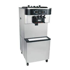
Taylor c713 Installation guide


C713 Operator TrainingC713 Operator Training
1
Introduction

C713 Operator TrainingC713 Operator Training
2
C713 Operator TrainingC713 Operator Training
Impact Servings:
How many servings can be drawn before the product becomes soft (unservable)?
Recovery Time: 1 - 2 minutes
Note: The soft serve draw rate is critical.
The rate must be 5 - 7.5 oz. (150 - 225 g.) per 10 seconds.
The way we measure
capacity is by how many
servings can be drawn before
the machine needs time to
recover the mix to the proper
viscosity.
The C713 can handle the
following impact servings:
35- 3.5 oz. Sundaes
Note: The machine needs 1-2
minutes of recovery time after
this level of impact servings. 35 servings
Impact Servings:
Consistency/Capacity

C713 Operator TrainingC713 Operator Training
3
A seven minute freeze-down time is necessary to make frozen product (18° F/-7.8° C) from liquid
mix (40° F/4.4°C).
Once the product is frozen, subsequent refrigeration cycles are necessary. The machine will cease
refrigeration for 10 minutes to maintain servable product during the day.
Product that is overbeaten is “broken down.” Broken down product is caused by longer than normal
freeze times.
Longer than normal freeze times can be caused by:
Worn scraper blades
Insufficient air space around the freezer
Dirty condensers or air filters
Loss of refrigerant (refrigerant leak)
Temperature

C713 Operator TrainingC713 Operator Training
4
C713 Operator TrainingC713 Operator Training
The product is too soft
Cause: Draw rate is set too fast.
Remedy: Adjust draw rate of 5 to 7.5 oz.
(142-213 g) of product by weight in 10 seconds.
The product is too thick.
Cause: Freezing cylinder not primed correctly.
Remedy: Drain the freezing cylinder and reprime
the machine.
Cause: The viscosity control is set too cold.
Remedy: Call an authorized service technician.
Cause: Freeze-up in mix inlet hole.
Remedy: Call an authorized service technician.
Cause: Mix feed tube is installed incorrectly or the
air orifice is not installed.
Remedy: Brush clean the machine and be sure to
install feed tube following the procedures in the
Taylor Operator's Manual.
The product is broken down.
Cause: The machine is running too long.
Remedy: Replace worn scraper blades,
clean air filter, and clean air cooled
condensers. Verify that there is proper air
space around the freezer. Call a service
technician to check the level of refrigerant.
Troubleshooting (Product)

C713 Operator TrainingC713 Operator Training
5
Make sure the mix low indicators on the front of the machine are off to assure successful operation
and product dispensing.
Milkstone build-up can cause an erroneous mix low indication.
Open the hopper lid and fill the
hopper with new mix. The indicator
light will turn off after the mix covers
the top sensor.
Mix Low

C713 Operator TrainingC713 Operator Training
6
C713 Operator TrainingC713 Operator Training
When the machine experiences a mix out condition, the machine enters the STANDBY mode of
operation.
Open the hopper lid and fill the
hopper with new mix. The mix out
indicator light will turn off after the
mix covers the bottom sensor. The
mix low indicator light will turn off
after the mix covers the top sensor.
Note: There may be a beeping
sound when a mix light is lit.
Mix Out

C713 Operator TrainingC713 Operator Training
7
After hour 99, the brush clean counter will change to a letter and a number (example: A0, A1...B0,
B1, etc.).
Brush Clean Counter
The Brush Clean Counter will
display the number of hours
since the freezer was last
brush cleaned.
02

C713 Operator TrainingC713 Operator Training
8
C713 Operator TrainingC713 Operator Training
Hard locks require that the machine be brush cleaned before it can return to the AUTO mode of
operation.
Typical Reasons:
HPR>41F (5C) AFTER 4 HR - The mix temperature in the hopper was above 41°F (5°C) more than
four hours.
BRL>41F (5C) AFTER 4 HR - The mix temperature in the freezing cylinder was above 41°F (5°C)
more than four hours.
HPR>41F (5C) AFTER PF - The mix temperature in the hopper was above 41°F (5°C) more than
four hours following a power failure.
BRL>41F (5C) AFTER PF - The mix temperature in the freezing cylinder was above 41°F (5°C)
more than four hours following a power failure.
HPR>45F (7C) AFTER 1 HR - The mix temperature in the hopper was above 45°F (7°C) more than
one hour.
BRL>45F (7C) AFTER 1 HR - The mix temperature in the freezing cylinder was above 45°F (7°C)
more than one hour.
HPR>59F (15C) - The mix temperature in the hopper exceeded 59°F (15°C).
BRL>59F (15C) - The mix temperature in the freezing cylinder exceeded 59°F (15°C).
Solution:
Turn off machine, disassemble and clean.
FREEZER LOCKED
Hard locks are designed to
insure product safety. The
machine will go into this mode
when the product mix quality
becomes compromised.
Hard Locks

C713 Operator TrainingC713 Operator Training
9
INTERACTIVE MODULE:
Move your mouse across the panel to learn what each part does.
Accessing Data

C713 Operator TrainingC713 Operator Training
10
C713 Operator TrainingC713 Operator Training
Menu Simulator
Click the switch to turn the power ON >>>

C713 Operator TrainingC713 Operator Training
11
The draw handle adjustment knob is intended to slow the product delivery speed.
+-
Use the screw on the draw handle to
control the speed of product dispensing.
For optimum product quality the rate of
dispensing should be 5 to 7.5 oz (142-213
g) in a 10 sec. draw. If the dispensing rate
is set higher or lower, the risk is poor
product quality and potential damage to the
machine.
To increase the flow rate, turn the screw
clockwise, and counter-clockwise to
decrease the flow rate.
Calibration: Draw Handle

C713 Operator TrainingC713 Operator Training
12
C713 Operator TrainingC713 Operator Training
Step 1
Before installing the beater drive shaft, lubricate the groove on the beater drive shaft.
Step 2
Slide the beater drive shaft boot seal over the small end of the beater drive shaft and engage into
the groove on the shaft.
Step 3
Heavily lubricate the inside portion of the boot seal and also lubricate the flat end of the boot seal
that comes in contact with the rear shell bearing.
Step 4
Apply an even coat of lubricant to the shaft. DO NOT lubricate the hex end.
Note: To ensure the mix does not leak out of the back of the freezing cylinder, the middle section of
the boot seal should be convex or extend out from the seal. If the middle section of the boot seal is
concave or extending into the middle of the seal, turn the seal inside out.
Step 5
Insert the beater drive shaft through the rear shell bearing in the freezing cylinder and engage the
hex end firmly into the drive coupling.
Step 6
Before installing the beater assembly, check the scraper blades. If they are in good condition,
take one of the scraper blades and slip it under the hook at the front of the beater. Wrap the blade
around the beater, following the helix and pushing the blade down onto the helix as you wrap. At the
back end of the beater, slip the blade under the hook.
Repeat this step for the second scraper blade.
Step 7
Holding the beater securely, slide the beater into the freezing cylinder about one-third of the way in.
Looking into the freezing cylinder, align the hole at the rear of the beater with the flats on the end of
the drive shaft.
Step 8
Slide the beater the remainder of the way into the freezing cylinder and over the end of the drive
shaft. The beater should fit snugly but not so tightly that the beater cannot be turned slightly to
engage the drive shaft.
Make sure the beater assembly is in position over the drive shaft. Turn the beater slightly to be
certain that the beater is properly seated. When in position, the beater will not protrude beyond the
front of the freezing cylinder.
Step 9
Repeat these steps for the other side of the machine.
Freezing Cylinder Assembly

C713 Operator TrainingC713 Operator Training
13
Freezing Cylinder Assembly
Step 10
To assemble the freezer door, place the door gaskets into the grooves on the back of the freezer
door. Slide the front bearings over the baffle rods. The flanged edges should be against the door. DO
NOT lubricate the gaskets or bearings.
Step 11
Slide the two o-rings into the grooves on each prime plug. Apply an even coat of Taylor Lube to the
o-rings and shafts.
Step 12
Insert the prime plugs into the holes in the top of the freezer door and push down.
Step 13
To install the freezer door, insert the baffle rods through the beaters in the freezing cylinders.
With the door seated on the freezer studs, install the handscrews. Use the long handscrews on the
top and the short handscrews on the bottom. Tighten them equally in a criss-cross pattern to insure
the door is snug.
Step 14
Slide the three o-rings into the grooves of each standard draw valve. Slide the H-ring and o-ring into
the grooves of the center draw valve. Lubricate the H-ring and o-rings.
Step 15
Lubricate the inside of the freezer door spouts, top and bottom.
Step 16
Insert the draw valves from the bottom until the slot in the draw valves come into view.
Step 17
Slide the fork of the draw handles in the slot of the draw valves, starting from the right. Slide the
pivot pin through each draw handle as they are inserted into the draw valves.
Note: This freezer features three adjustable draw handles to provide portion control, giving a better
consistent quality to your product and controlling costs. The draw handle should be adjusted to pro-
vide a flow rate of 5 to 7-1/2 oz. (142 g. to 213 g.) of product by weight per 10 seconds.
To INCREASE the flow rate, turn the adjustment screw CLOCKWISE. Turn the adjustment screw
COUNTER-CLOCKWISE to DECREASE the flow rate.

C713 Operator TrainingC713 Operator Training
14
C713 Operator TrainingC713 Operator Training
Step 18
Snap the design caps over the bottom of the door spouts.
Step 19
Slide the two drip pans into the holes in the side panels.
Step 20
Install the front drip tray and splash shield under the door spouts.
Step 21
Slide two o-rings on one end of the feed tube. Slide two o-rings on the other end of the feed tube.
Step 22
Slide the small o-ring into the groove of the air orifice. Do not lubricate the o-ring.
Note: Make sure the hole in the air orifice is clean and is not clogged. If the hole in the air orifice
should become clogged, use soap and hot water to clear the hole. Do not enlarge the hole in the air
orifice.
Step 23
Install the air orifice into the hole in the top of the feed tube (end without the small hole on the side).
Step 24
Lay the feed tube (with the air orifice installed) in the bottom of the mix hopper for sanitizing.
Step 25
Repeat steps 21 through 24 for the other side of the machine.

C713 Operator TrainingC713 Operator Training
15
If the mix gets too cold, the reset button will “trip” to protect the beater motor. This could be caused
by insufficient mix in the freezing cylinder. If this occurs, inspect the feed tube to verify that it is
properly assembled.
Freezing Cylinder: Reset

C713 Operator TrainingC713 Operator Training
16
C713 Operator TrainingC713 Operator Training
Freezing Cylinder: Checklist
1. Replace scraper blades that are nicked or damaged. Before installing
beater, be certain that scraper blades are properly attached.
2. Check rear shell bearing for signs of wear (excessive mix leakage in
side drip pan) and be certain it is properly cleaned.
3. Using a brush and cloth towel, keep the rear shell bearing and the
female hex drive socket clean and free of lubricant and mix deposits.
4. Dispose of o-rings and seals if they are worn, torn, or fit too loosely, and
replace with new ones.
5. Follow all lubricating procedures as outlined in "Assembly"
6. Check the condenser and filters for accumulation of dirt and lint. A dirty
condenser or filter will reduce the efficiency and capacity of the
machine. The condenser should be cleaned monthly with a soft brush.
The filter should be cleaned weekly.
7. On water cooled units, check the water lines for kinks or leaks. Kinks
can occur when the machine is moved back and forth for cleaning or
maintenance purposes. Deteriorated or cracked water lines should be
replaced only by an authorized Taylor mechanic.

C713 Operator TrainingC713 Operator Training
17
Step 1
Prepare an approved 100 PPM sanitizing solution (examples: 2-1/2 gal. [9.5 liters] of Kay-5® or 2
gal. [7.6 liters] of Stera-Sheen®). USE WARM WATER AND FOLLOW THE MANUFACTURER'S
SPECIFICATIONS.
Step 2
Pour the sanitizing solution over all the parts in the bottom of the mix hopper and allow it to flow into
the freezing cylinder.
Note: You have just sanitized the mix hopper and parts; therefore, be sure your hands are clean and
sanitized before going on in these instructions.
Step 3
Pour the sanitizing solution into the mix hopper.
Step 4
Brush the exposed sides of the hopper.
Step 5
Place the power switch in the ON position.
Step 6
Touch the WASH symbol. This will cause the sanitizing solution in the freezing cylinder to be
agitated.
Step 7
With an empty pail beneath the door spouts, raise the prime plug.
Step 8
When a steady stream of sanitizing solution is flowing from the prime plug opening in the bottom of
the freezer door, open the draw valve. Momentarily open the center draw valve to sanitize the center
door spout. Draw off the remaining sanitizing solution.
Step 9
Once the sanitizer stops flowing from the door spout, touch the WASH symbol and close the draw
valve.
Note: Be sure your hands are clean and sanitized before going on in these instructions.
Step 10
Lubricate the feed tube o-rings on the end with the small hole on the side. Stand the feed tube in the
corner of the hopper.
Step 11
Repeat these steps for the other side of the machine.
Sanitizing

C713 Operator TrainingC713 Operator Training
18
C713 Operator TrainingC713 Operator Training
Priming
Note: Use only FRESH MIX when priming the freezer.
Step 1
Place an empty mix pail beneath the door spouts. With the prime plug in the UP position, pour 2-1/2
gallons (9.5 liters) of FRESH mix into the mix hopper and allow it to flow into the freezing cylinder.
Open the draw valve to remove all sanitizing solution. When only fresh mix is flowing, close the draw
valve.
Step 2
Once a steady stream of mix starts to flow from the prime plug opening in the bottom of the freezer
door, push the prime plug down.
Step 3
Install the end of the feed tube with the hole in it into the mix inlet hole in the mix hopper. Make sure
the air orifice is installed in the feed tube.
Step 4
Select the AUTO symbol.
Fill the hopper with fresh mix and place the mix hopper cover in position.
Repeat these steps for the other side of the machine.
Other manuals for c713
1
Table of contents
Other Taylor Commercial Food Equipment manuals
Taylor
Taylor Taylormate 152 Instruction Manual

Taylor
Taylor C300 NP User manual
Taylor
Taylor 358 User manual

Taylor
Taylor QS Series User manual

Taylor
Taylor C850 User manual

Taylor
Taylor Turbo Charge 8752 Installation guide
Taylor
Taylor C712 Installation guide

Taylor
Taylor 8664 User manual

Taylor
Taylor C602 User manual

Taylor
Taylor 490 Installation guide
Popular Commercial Food Equipment manuals by other brands

RPI
RPI SNACKY WK Operating and maintenance instructions

Fri-Jado
Fri-Jado TDR auto-clean Series Service manual

Diamond
Diamond STAR-HD/RX Installation

Interlevin
Interlevin PT920 user manual

VarioCooking Center
VarioCooking Center WHITEFICIENCY Series Original technical instructions

ACP
ACP AXP20 instruction sheet