Taymor Premier Line 1948 User manual
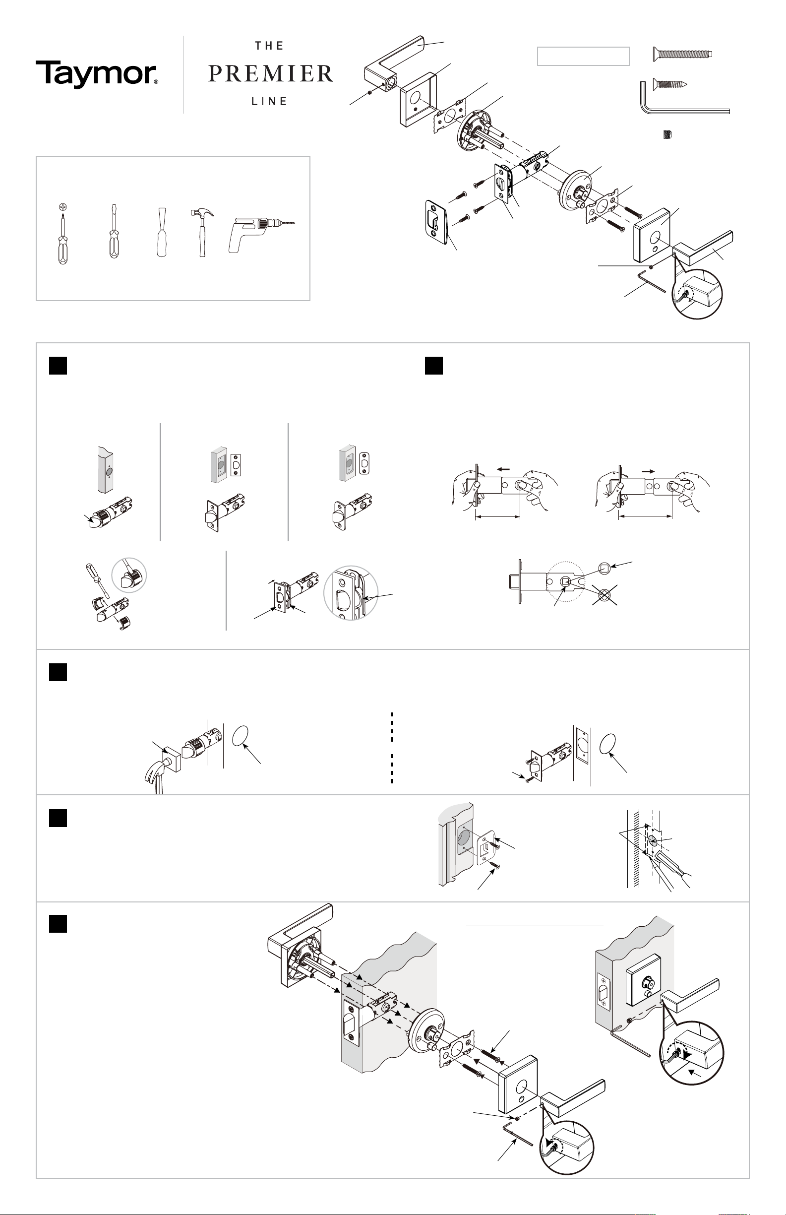
INSTALL LATCH
A. Drive-in Latch: Insert latch into the door edge and tap it into place using a wood
block (not included) until it is flush with the door edge.
3
B. Faceplate Latch: Secure to the door edge using latch screws (BB). If it does not sit
flush with the door edge, mark an outline using the faceplate and chisel 1/8”
(3 mm) deep or until the faceplate is flush.
OR
(BB)
WOOD BLOCK
BORE HOLE
BORE HOLE
TOOLS NEEDED
CAUTION: Use of manual tools recommended. When using power tools,
adjust to lowest torque setting.
PHILLIPS
SCREWDRIVER
FLAT HEAD
SCREWDRIVER
(OPTIONAL)
CHISEL
(OPTIONAL)
HAMMER
(OPTIONAL)
HAND DRILL
(OPTIONAL)
12
CHOOSE YOUR LATCH TYPE
To change the latch from a drive-in latch to a faceplate latch, remove the sleeve using
a screwdriver (A1), attach selected faceplate to backplate (A2) and fasten to latch.
DRIVE-IN
LATCH SQUARE FACEPLATE
MORTISE LATCH RADIUS FACEPLATE
MORTISE LATCH
REMOVE
SLEEVE
ADJUST THE BACKSET
The backset is the distance from the door edge to the center of the spindle cam.
The spindle cam must sit straight (B3) and at the center of the bore hole to install
the lever. The two most common backset measurements are 2-3/8” (60 mm) or
2-3/4” (70 mm). To change the backset from 2-3/8” (60 mm) (B1) to 2-3/4” (70 mm)
(B2) pull the spindle cam away from the faceplate.
A1 A2
BACKPLATE
NOTE: The bevel of
latch bolt should
face the door jamb
B3 SPINDLE CAM
RIGHT
WRONG
MUST SIT IN
CENTRE OF DRILLED
DOOR HOLE
B1 B2
2-3/8 (60 mm) 2-3/4 (70 mm)
ENSURE LIP OF
BACKPLATE IS
FACING TOWARDS
FACEPLATE
INSTALL STRIKE PLATE
A. Secure the strike plate to the door jamb using wood strike screws (BB).
B. If there is no hole for the latch bolt, mark a centerline on the door jamb that aligns with
the centerline of the door latch. Drill one 1” (25 mm) hole 5/8” (16 mm) deep.
C. Use the strike plate to make an outline on the door jamb and chisel 1/8” (3 mm) deep
until it sits flush.
D. Drill two 1/8” (3 mm) drill holes and secure the strike plate to the door jamb.
4
(BB)
STRIKE PLATE
1/8” (3 mm) ONE (1) 1” (25 mm)
HOLE
5/8” (16 mm)
DEEP
FACEPLATE
INSTALL LOCKSET
A. Remove the interior lever from the lock
mechanism by loosening the set screw
with the Allen Key (CC). Remove the
interior rose by twisting and pulling it off
the interior lock mechanism.
B. Install exterior lock assembly inserting
square spindle and posts through latch.
Note: For privacy functions, the emer-
gency release hole can be positioned
either above or below the lever.
Note: For entry function, spindle must be
positioned vertically.
C. Attach the interior lock assembly to the
exterior assembly using the mounting
screws (AA). Note: For privacy functions,
ensure the lock button aligns with the
emergency release hole on the exterior
side.
D. Re-attach interior rose to lock mecha-
nism.
E. Re-attach interior lever with the set
screw (DD) using the Allen Key (CC).
5
CONTINUED ON BACK PAGE
EXTERIOR INTERIOR
EXTERIOR SIDE
INTERIOR SIDE
Note: To ensure correct alignment of the lever, tighten the mounting screws
on the interior lock mechanism while holding the exterior lever upwards.
REPLACING AN EXISTING LOCK (NO DOOR PREPARATION NECESSARY)
INSTALLATION INSTRUCTIONS FOR 1948 STYLE
COMPONENTS AA Mounting Screws (2)
BB Latch & Strike Plate Screws (4)
CC Allen Key (1)
DD Set Screws (2)
Exterior Rose Bracket
Latch
Exterior Lever
Rose Cover
Exterior Rose &
Lock Assembly
Set Screw
Interior Rose Bracket
Allen
Key
Interior Lever
Interior
Rose
Lock Assembly
Face Plate
Set Screw
Back Plate
Strike Plate
.
D.
B.
C.
AA
DD
CC
A.
E.

CONTINUED FROM FRONT PAGE
CUSTOMER SERVICE
WESTERN CANADA 1-800-267-4774 | EASTERN CANADA 1-800-387-7064 | USA 1-800-388-9887
taymor.com
® REGISTERED TRADEMARK OF TAYMOR INDUSTRIES LTD.
JAN. 2018
Drill a 1” (25 mm) diameter hole
at the center of the door edge.
1-3/4”
(45 mm) 1-3/8”
(35 mm)
Fold here.
Place on the door edge.
Backset - 2-3/8” (60 mm)
Backset - 2-3/4” (70 mm)
ø2-1/8” (54 mm)
DOOR PREPARATION TEMPLATE
CHANGE LEVER HANDING
A. Remove the set screw on the side of the lever using the Allen Key.
B. Swap levers. Align the hole on the lever with the catch hole on the rose and press until secure.
Reinstall the set screw. Tighten using the long leg of the Allen Key.
EXTERIOR VIEW
LEFT HANDED
SET SCREW & ALLEN KEY (CC & DD)
RIGHT HANDED
✃
USE TEMPLATE PROVIDED TO MARK CENTER HOLES ON THE DOOR
A. Stand so the door swings towards you. Fold the template over door edge
approximately 36” (914 mm) from the floor.
”
CENTERLINE
36” (914 mm) FROM FINISHED FLOOR BACKSET 2-3/8” (60 mm) - 2-3/4” (70 mm))
2-1/8” (54 mm)
CENTERLINE
1” (25 mm)
TEMPLATE
B. Make a center mark for a 1” (25 mm) hole on the door edge and a center mark for a 2-1/8”
(54 mm) hole on the door surface.
C. Drill the 2-1/8” (54 mm) door surface hole. Drill the 1” (25 mm) hole to meet surface hole.
Note: Drill surface hole from both sides to reduce risk of wood splitting.
CARING FOR YOUR LOCK
Our locksets are polished and then protected with a coating to help prevent tarnishing. This protective coating has limitations and in time may deteriorate
from handling, cleaning or exposure to atmospheric conditions such as extreme climate, pollution and proximity to salt water, humidity and ultraviolet rays.
Eventual tarnishing is, therefore, not a defect, but a normal process which is unavoidable. With proper care, these products will last a long time.
To care for your lock, wash and clean only with water and polish with a soft, clean cloth.
1 INCH
IMPORTANT: Print template to scale if not factory supplied instructions.
See other side for lock installation instructions.
LIFETIME MECHANICAL AND FINISH WARRANTY
This product is warranted to be free from finish, mechanical and workmanship defects for the life of the product. Taymor Industries Ltd. will replace
any Taymor Premier series lock which fails to meet this warranty. Any finish deterioration occurring from use of paints, solvents or other chemicals is
not a defect and therefore is not covered by this warranty. Taymor Industries Ltd. is not liable for incidental or consequential damages.
If your Taymor lock does not meet the warranted quality, return the product with proof of purchase information to the Taymor dealer from which the
product was purchased. Go to taymor.com for full warranty information.
NEW DOOR PREPARATION
1
NOTE: For beveled doors, apply template to pull side of door.
Other Taymor Door Lock manuals


