6
Assemble the AC Cables
Step 4. Lock the 4*M4 screws and fix the cover onto the inverter.
WARNING:
Observe the terminal layout of terminal block.
Do not connect the phase lines to“PE”terminal, otherwise the
inverter will not function properly.
5
Assemble the Battery Cables
WARNING:
Incorrect polarity of the battery cable may lead to permanent
damage on the device.
WARNING:
For protection, Solis recommends installing a DC switch
between the battery and the inverter.
Ensure the correct polarity of batteries before connecting
to the inverter.
Step 1. Please unlock the 4*M4 screws on the battery port
protection cover as shown in the below figure.
Step 2. Insert the battery power cables (in package) into the
water-proof swivel nut on the cover, (Break the plastic film on it).
Step 3. Fasten the battery power cables onto the BAT+ and BAT-
terminals on the inverter.
Please make sure the labels on cable and inverter match up.
Step 4. Lock the 4*M4 screws and fix the cover onto the inverter.
Step 5. Connect the other side of the battery power cables to the
battery.
BAT(+) Battery(+)
BAT(-) Battery(-)
External Ground Connection
An external ground connection is provided at the right side of
the inverter. Prepare OT terminals: M4. Use proper tooling to
crimp the lug to the terminal. Connect the OT terminal with
ground cable to the right side of inverter. The torque is 2N.m.
Grounding screw
7
8
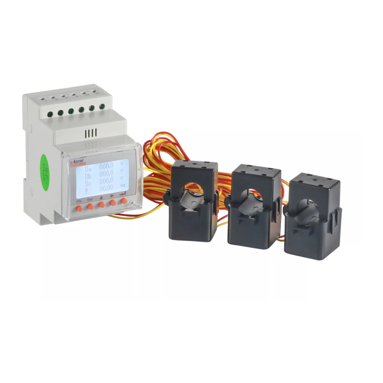
S6-EA1P3K-L-S inverter requires a smart meter to measure
the power flow at the grid connection point to achieve the
self-use control algorithm.
The smart meter and the communication cable are provided
as a standard accessory in the package. Please refer to
below system diagram to connect the smart meter at the grid
connection point. Meanwhile, a smart CT sensor is provided
in order to measure the generation of grid-tied PV inverter.
Meter Installation
M4 cross screws
Step 1. Please unlock the 4*M4 screws on the AC ports protection
cover as shown in the below figure.
Step 2. Insert the AC grid cables cables into the corresponding
water-proof swivel nut on the cover, (Break the plastic film on it).
Make sure you use a cable within the correct specifications as
shown in the table below.
Remove a length of 40mm of the cable jacket and strip the wire
insulation to a length of 10-12mm.
Describe
Wire diameter 10~12mm
2.5~6mm²
12mm
Traverse cross sectional area
Exposure Length
Numerical value
40 mm
10 mm - 12 mm
PE
L
N
Step 3. Fasten the AC cables onto the terminals on the inverter.
Please make sure the correct polarity. Ensure that the correct
conductor is fastened (0.7 N.m. torque) to the correct terminal.
M4 cross screws


