TBK vision TBK-1020HVLD78IR User manual

!
!
CAUTION
RISK OF ELECTRIC SHOCK
DO NOT OPEN
CAUTION TO REDUCE THE RISK OF
ELECTRIC SHOCK.
DO NOT REMOVE COVER(OR BACK).
NO USER SERVICEABLE PARTS INSIDE.
REFER SERVICING TO QUALIFIED SER-
VICE PERSONNEL.
Operating Instructions
Operating Instructions
Operating Instructions
Before installing and using the camera, please read the
instructions thoroughly and retain them for reference.
1/3” True Day&Night IR Vari-Focal
Water Resistant Camera
IR BULLET
This symbol is intended to alert the user to the presence
of noninsulated “dangerous voltage” within the product’s
enclosure that may be of sufficient magnitude to constitute
a risk of electric shock to persons.
The exclamation point within an equilateral triangle is
intended to alert the user to the presence of important
operating and maintenance (servicing) instructions in
the literature accompanying the product.
To prevent fire or shock hazard, do not expose this appliance
to rain or moisture.
To avoid electrical shock, do not open the cabinet.
Refer servicing to qualified personnel only.
Wiring methods shall be in accordance with the National Electric Code.
2
Caution
OperaTIng InsTrucTIons
Warning
This product is manufactured to comply with
the CE and FCC Certificate standard.
!
!
CAUTION
RISK OF ELECTRIC SHOCK
DO NOT OPEN
CAUTION TO REDUCE THE RISK OF
ELECTRIC SHOCK.
DO NOT REMOVE COVER(OR BACK).
NO USER SERVICEABLE PARTS INSIDE.
REFER SERVICING TO QUALIFIED SER-
VICE PERSONNEL.
Operating Instructions
Operating Instructions
Operating Instructions
Before installing and using the camera, please read the
instructions thoroughly and retain them for reference.
1/3” True Day&Night IR Vari-Focal
Water Resistant Camera
IR BULLET
This symbol is intended to alert the user to the presence
of noninsulated “dangerous voltage” within the product’s
enclosure that may be of sufficient magnitude to constitute
a risk of electric shock to persons.
The exclamation point within an equilateral triangle is
intended to alert the user to the presence of important
operating and maintenance (servicing) instructions in
the literature accompanying the product.
To prevent fire or shock hazard, do not expose this appliance
to rain or moisture.
To avoid electrical shock, do not open the cabinet.
Refer servicing to qualified personnel only.
Wiring methods shall be in accordance with the National Electric Code.
2
Caution
OperaTIng InsTrucTIons
Warning
This product is manufactured to comply with
the CE and FCC Certificate standard.

Operating Instructions
3
Precautions 4
To prevent electric shock, do not remove screws or covers. There
are no user serviceable parts inside. Ask a qualified service
personnel for servicing.
Do not attempt to disassemble the camera.
Composition 5
Features 6
7Name of Each Part
8Installation
9Troubleshooting
10Specifications
11Dimension
9Notes on installation and usage
8Camera installaton
Explanation of Accessories 5
Contents
4
Do not aim the camera at bright objects. Never face it with direct
sunlight or other extremely bright object. Otherwise blooming or
smear may be caused.
Avoid facing the camera with direct sunlight.
Use a dry cloth to the camera when it is dirty. If it is hard to remove
the dirt on the camera, use a mild detergent and wipe it gently.
Do not use strong solvents or detergents.
Do not abuse the camera. Avoid striking, shaking, etc. The camera
could be damaged by improper handling or storage.
Handle the camera with care.
Do not use in a room or area filled with cigarette smoke, dust or gas.
Do not expose the camera in such conditions
shown below.
Before operating, please check proper tempe-
rature, humidity and power source ratings.
OperaTIng InsTrucTIons
Precautions
Operating Instructions
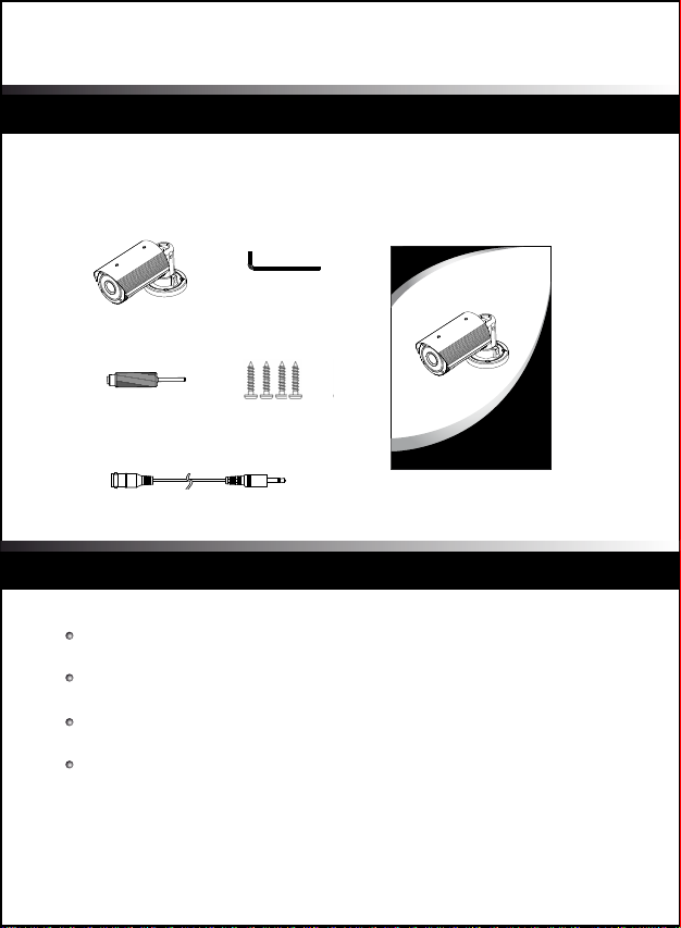
Confirm that the following parts are included: 1/3” Sony Super HAD(Ex-view HAD) CCD
550 TV Lines (Color) and 580TV Lines (B/W) Resolution
Minimum Scene Illumination 0 Lux (with LED On)
IR range Distance up to 60m
Color & B/W Auto switchable by Photocell and Sensitivity
Built-in 18~50mm/F1.5 Day & Night Vary-Focal DC Auto Iris Lens
Externally Adjustable Focal Length & Focus with Lever
Externally Adjustable DC Iris Level
CDS Photocell Auto Switching IR-LED Control 42 LEDs
(On : 5 Lux / Off : 3 Lux)
Built-in Fan & Heater
Cable Managed Bracket
Service Monitor Output
Water Resistant (IP-66)
AC24V / DC12V
Camera L-Wrench
Screws
Instruction Manual
5
6
Service Monitor Cable
OperaTIng InsTrucTIons
OperaTIng InsTrucTIons
OperaTIng InsTrucTIons
Before installing and using the camera, please read the
instructions thoroughly and retain them for reference.
1/3” True Day&Night IR Vari-Focal
Water Resistant Camera
OPTIMUS
IR BULLET
Composition Features
Explanation for accessories
Driver
L Wrench - Unscrew and tighten bracket screw.
Driver - To control DC Iris Level and Service video port.
Screw - To firmly attach the bracket to the wall or ceiling.
Service Monitor Cable - Monitoring the display screen through portable
monitor to adjust the camera.

Operating Instructions
Confirm that the following parts are included: 1/3” Sony Super HAD(Ex-view HAD) CCD
550 TV Lines (Color) and 580TV Lines (B/W) Resolution
Minimum Scene Illumination 0 Lux (with LED On)
IR range Distance up to 60m
Color & B/W Auto switchable by Photocell and Sensitivity
Built-in 18~50mm/F1.5 Day & Night Vary-Focal DC Auto Iris Lens
Externally Adjustable Focal Length & Focus with Lever
Externally Adjustable DC Iris Level
CDS Photocell Auto Switching IR-LED Control 42 LEDs
(On : 5 Lux / Off : 3 Lux)
Built-in Fan & Heater
Cable Managed Bracket
Service Monitor Output
Water Resistant (IP-66)
AC24V / DC12V
Camera L-Wrench
Screws
Instruction Manual
5
6
Service Monitor Cable
OperaTIng InsTrucTIons
OperaTIng InsTrucTIons
OperaTIng InsTrucTIons
Before installing and using the camera, please read the
instructions thoroughly and retain them for reference.
1/3” True Day&Night IR Vari-Focal
Water Resistant Camera
OPTIMUS
IR BULLET
Composition Features
Explanation for accessories
Driver
L Wrench - Unscrew and tighten bracket screw.
Driver - To control DC Iris Level and Service video port.
Screw - To firmly attach the bracket to the wall or ceiling.
Service Monitor Cable - Monitoring the display screen through portable
monitor to adjust the camera.
Operating Instructions
87
OperaTIng InsTrucTIons
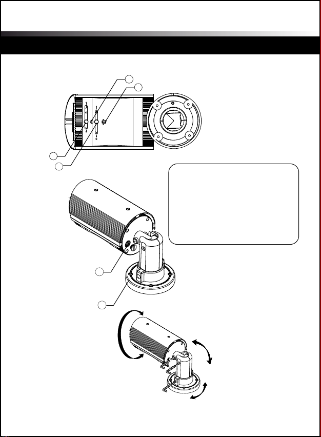
Name of each part Installation
T W
N
H
DC LEVEL
L
1
3
2
4
5
6
1. ZOOM LEVER
2. FOCUS LEVER
3. FOCUS / ZOOM BOLT SCREW
4. DC LEVEL VOLUME SCREW CAP
5. SERVICE VIDEO PORT
6. BRACKET
Zoom and Focus Lever
Loosen the levers and adjust Zoom/Focus.
After controlling, tighten each lever.
1. Zoom Lever
- To widen the viewing angle, turn the “Zoom Lever” to “W”(Wide)
- To obtain a closer view, turn this Lever to “T” (Tele).
2. Focus Lever
- To adjust the Focus between “N” (Near) or “ ” (Far) until the
sharpest focus is achieved.
3. Focus / Zoom Bolt Screw
Be careful not to lose these small bolts/screws which should not
be touched in normal use.
4. DC Level Volume Screw Cap
Remove this screw Cap carefully. Retain it in a safe place
as it must be replaced to protect from water entering the camera body.
Beneath the Screw is the DC level adjustment Pot.
- For a bright screen, turn the DC level Pot slowly
towards “H” (counter-clockwise) with the driver provided.
- For a dark screen, turn it towards “L” (clockwise).
Then tighten the Screw Cap to protect water entering
5. Service Video Port
Unscrew the service monitor screw and attach the supplied service
monitor cable to adjust the display screen. After finishing the proper
adjustment, detach the service monitor cable and screw back and tighten.
6. Bracket
Loosen the Pan/Tilt bolts of the bracket to adjust the camera direction.
In reference to page 7.
Camera Installation
PAN TILT ADJUSTMENT

Operating Instructions
87
OperaTIng InsTrucTIons
Name of each part Installation
T W
N
H
DC LEVEL
L
1
3
2
4
5
6
1. ZOOM LEVER
2. FOCUS LEVER
3. FOCUS / ZOOM BOLT SCREW
4. DC LEVEL VOLUME SCREW CAP
5. SERVICE VIDEO PORT
6. BRACKET
Zoom and Focus Lever
Loosen the levers and adjust Zoom/Focus.
After controlling, tighten each lever.
1. Zoom Lever
- To widen the viewing angle, turn the “Zoom Lever” to “W”(Wide)
- To obtain a closer view, turn this Lever to “T” (Tele).
2. Focus Lever
- To adjust the Focus between “N” (Near) or “ ” (Far) until the
sharpest focus is achieved.
3. Focus / Zoom Bolt Screw
Be careful not to lose these small bolts/screws which should not
be touched in normal use.
4. DC Level Volume Screw Cap
Remove this screw Cap carefully. Retain it in a safe place
as it must be replaced to protect from water entering the camera body.
Beneath the Screw is the DC level adjustment Pot.
- For a bright screen, turn the DC level Pot slowly
towards “H” (counter-clockwise) with the driver provided.
- For a dark screen, turn it towards “L” (clockwise).
Then tighten the Screw Cap to protect water entering
5. Service Video Port
Unscrew the service monitor screw and attach the supplied service
monitor cable to adjust the display screen. After finishing the proper
adjustment, detach the service monitor cable and screw back and tighten.
6. Bracket
Loosen the Pan/Tilt bolts of the bracket to adjust the camera direction.
In reference to page 7.
Camera Installation
PAN TILT ADJUSTMENT

Operating Instructions
1. Do not disassemble the camera.
2. Always handle the camera with care. Please avoid mechanical shock
or vibration, and take caution to prevent damages or make scratches
on the camera glass due to careless storage and/or handling.
3. Do not clean the camera body with strong abrasives or soaps. When
the camera becomes dirty, clean it with dry rugs. Take precaution to
use dedicated rugs to clean glass.
4. Please keep the camera in a cool area that is not exposed to direct
sunlight. Failing to do so can cause undesired effects on the product.
Notes on installation and usage
Nothing appears on the screen.
ㅡ>Check the power connection and video signal line connection.
ㅡ>Check the brightness level of DC Auto Iris volume of the camera.
The screen is dark
ㅡ>Adjust the brightenss feature of the monitor.
ㅡ>Check the brightness level of DC Auto Iris volume of the camera.
The video image is not clear.
ㅡ>Check if the camera glass has dust on the surface.
Clean the camera glass with a clean cloth or brush.
ㅡ>Make sure that the screen is not exposed directly to a bright light.
Adjust the position of the camera if necessary.
ㅡ>Check if protective film of camera glass is removed.
The screen does not properly display when IR LEDs work.
ㅡ>Check if the camera glass has dust.
Clean the camera glass with a clean cloth or brush.
If you have trouble operating the camera, check the following
guides for the possible problem.
If you cannot solve the problem with above guidelines,
please contact an authorized technician.
9
10
ITEM
Image Sensor
Effective Pixels
Scanning System
Scanning Frequency
Resolution
Shutter Speed
S/N Ratio
Sync. System
Min. Illumination
Video Output
Lens 18~50mm Day&Night Vari-Focal DC Auto Iris Lens (F1.5)
Power Supply
Power
Consumption
Operating Temp
Operating Humidity
Dimension
1/3” Interline transfer type color CCD (Sony)
768H x 494v (380K pixels) 752H x 582v (440K pixels)
525 Lines 2:1 Interlace 625 Lines 2:1 Interlace
15.734KHz(H), 59.94Hz(V) 15.625KHz(H), 50Hz(V)
550 TVL(Color), 580TVL(B/W)
1/60 sec.
More than 48dB (AGC Off)
Internal
0 Lux with IR-LED (42pcs)
VBS 1.0 Vp-p (75 ohm Load)
Normal : 250mA, Max : 900mA / DC12V
Normal : 4.8VA, Max : 20VA /AC24V
90% RH max
98mm( ) x 162.5mm( L )
1/50 sec.
NTSC PAL
AC24V / DC12V + 10%
OperaTIng InsTrucTIons
Troubleshooting
Specifications
Operating Instructions
1/3” True Day&Night IR Vari-Focal Water Resistant Camera
MADE IN KOREA
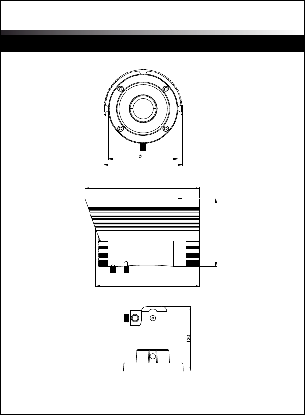
Unit : mm
11
OperaTIng InsTrucTIons
162.5
104.8
190.0
98.0
111.6
Dimension

Operating Instructions
1/3” True Day&Night IR Vari-Focal Water Resistant Camera
MADE IN KOREA
Unit : mm
11
OperaTIng InsTrucTIons
162.5
104.8
190.0
98.0
111.6
Dimension
Table of contents
Other TBK vision IP Camera manuals


Popular IP Camera manuals by other brands

PTZOptics
PTZOptics PT12X-USB-GY-G2 user manual

Planet
Planet ICA-HM100 quick guide

ID View
ID View IV-PDV3122MP instruction manual

Arecont Vision
Arecont Vision MegaDome AV3155 Specifications

Marmitek
Marmitek IP EYE ANYWHERE 10 - SOFTWARE ULTRAVIEW Software user's guide

Hunt Electronic
Hunt Electronic HTC-7AH36D Instruction guide


