TCL TFC-24HRA User manual

TCL
FLOOR-STANDING SPLIT-TYPE AIR CONDITIONERS
SERVICE MANUAL No.20180321
Models
TFC-24HRA/TOC-24HNA
TFC-48HRA/TOC-48HSA
CONTENTS
1. IMPORTANT NOTICE
2. PRODUCT DIMENSIONS
3. REFRIGERATION CYCLE DIAGRAM
4. OPERATION DETAILS
5. WIRING DIAGRAM
6. EXPLOSION VIEW AND PART LISTS
7. PRECAUTION
8. NAMES OF PARTS
9. INSTALLATION
10. TROUBLE SHOOTING

Air Conditioner Service Manual
1
1. IMPORTANTNOTICE
This service manual is intended for use by individuals possessing adequate
backgrounds of electrical, electronic and mechanical experience. Any
attempt to repair the appliance may result in personal injury and property
damage. The manufacturer or seller cannot be responsible for the
interpretation of this information, nor can it assume any liability in
connection with its use.
The information, specifications and parameters are subject to change due
to
technical modification or improvement without any prior notice. The
accurate specifications are presented on the nameplate label.
How to order spare parts
To have your order filled promptly and correctly, please furnish the
following information:
6
Model No. with Indoor or Outdoor
7
Part No. in the Explosion View
8
Part Name
9
The quantity you ordered

TCL Air Conditioner Service Manual
3
2.PRODUCT DIMENSIONS
Indoor Unit:
Outdoor Unit:
Model Indoor unit
Outdoor unit
A
B
C
D
E
F
G
H
I
J
K
TFC
-24HRA
480
330
1740
900
650
307
623
399
349
65
63
TFC-48HRA
540
420
1780
940
1250
340
600
400
375
50
63
Indoor unit
Outdoor unit
TFC

Air Conditioner Service Manual
3
3. Refrigeration cycle diagram
Cooling only
Heat pump
Capillary
Compressor
Accumulator
Heat exchange
(condenser)
Heat exchange
(Evaporator)
2-way valve
Liquid side
3-way valve
Gas side
Cooling
Heating
Gas side
3-way valve
Liquid side
2-way valve
Heat exchange
(Evaporator)
Heat exchange
(condenser)
Accumulator
Compressor
4-way valve
Capillary Assembly
Check valve

4
Note: Each mode and relevant function will be further specified in following pages.
Remote controller
Air Conditioner Service Manual
4.Operation Details
Remote Control
The remote controller is not presetting as Cooling Only Air Conditioner or Heat Pump by manufacturer.
Each time after the remote controller replace batteries or is energized, the arrowhead will flashes on the
front of Heat or Cool on LCD of the remote controller.
User can preset the remote controller type depending on the air conditioner type you have purchased as
follows:
Press any button when the arrowhead flashes on the front of Cool , Cooling Only is set.
Press any button when the arrowhead flashes on the front of Heat , Heat Pump is set.
If you don t press any button within 10 seconds, the remote controller is preset as Heat Pump
automatically.
Note :
If the air conditioner you purchased is a Cooling Only one, but you preset the remote controller as Heat
Pump, it doesn t bring any matter. But if the air conditioner you purchased is a Heat Pump one, and you
preset the remote controller as Cooling Only, then you CAN NOT preset the Heating operation with the
remote controller.
9
9
1
2
4
3
5
6
10
7
MODE button
ECO button
FAN SPEED button
TEMP UP button
TIMER button
SLEEP button
TEMP DOWN button
To select the mode of operation.
In cooling mode,press this button ,the temperature
will increase 2 on the base of setting temperature:
In heating mode, press this button, the temperature
will decrease 2 on the base of setting temperature.
To switch the conditioner on and off.
To select the fan speed of auto/low/mid/high.
To set automatic switching-on/off.
Increase the temperature or time by 1 unit.
To activate the function SLEEP .
Decrease the temperature or time by 1 unit.
8
DISPLAY button
In cooling mode, press this button, the unit will give
the maximum cooling temperature with 16
In heating mode, press this button, the unit will give
the maximum heating temperature with 31 .
9
SWING button
11
To activate or deactivate of the movement of the
DEFLECTORS .
13
HEALTH button
To switch - on /off HEALTHY funtion.
It is a button
which controls the ionizer or plasma generator only
for inverter type.
ON/OFF button
12
To LED display (if present)switch on/off the
3
4
2
1
9
5
67
8
10
11
12
ECO
13
TURBO button
9
SWING button
To activate or deactivate of the movement of the
DEFLECTORS .
9
10

Air Conditioner Service Manual
5
Electronic controller
NOTES:
RT-------Room Temperature.
IPT------Indoor Pipe Temperature.
ST------indoor Setting Temperature.
OPT---Outdoor Pipe Temperature.
CRT---Compensated Room Temperature
1. Automatic mode
1) The initial RT determines A/C working mode and the setting temperature (ST), the mode is
determined effective only once unless A/C shut-down and then re-started. If from other mode
switches to automatic mode (including mode conversion after shutdown), it should be that the
compress stop more than 3 min then temperature judgment and automatic mode are conducted (it
can conduct immediately from fan mode switched to automatic, the indoor fan stops, three minutes
later the response is made and start up). Within 3 min, the output as: Showing the room
temperature, indoor fans starts (or anti-cold airflow), the outdoor fan stops;
With auto re-start controller, once being turned off or in case of an accidently power cut, the
A/C is able to retain and restore the original mode when being turned on or the power supply
is resumed, if the autorestart function activated. power-off after power-on; while if the auto
restart function isn’t activated, the A/C enters standby state.
Heat pump
Mode Initial RT Initial ST
Cooling RT≥26°C 23°C
Dry 26°C>RT≥20°C 7°C
Heating RT<20°C 23°C
Cooling-only
Mode Initial RT Initial ST
Cooling RT≥26°C 23°C
Dry 26°C>RT≥20°C 7°C
Ventilating RT<20°C -
Under automatic mode (including from automatic converted into Dry mode), when A/C received the
temperature UP or DOWN signals from the remote controller, the setting temperature (ST)
adjusts
correspondingly to the current room temperature plus or minus 1°C, the automatic regulating
temperature range is ± 2°C.
2. Cooling mode
1) The control of the compressor
a.
When RT-ST≥1°C,the compressor is running.
b.
When RT-ST<-1°C,the compressor stops.
c.
When-1°C≤RT-ST<1°C, the compressor keeps its original state.
2) Outdoor fan motor and the compressor run simultaneously (except for defrosting).
3) The control of indoor fan motor:
a.
Indoor fan motor can operate by automatic, low, middle, or high airflow speed circularly.

Air Conditioner Service Manual
6
b.
Indoor fan motor automatic airflow speed control, it works as shown in Figure 1:
Hi
Mid
Lo
RT-ST 1°C 2°C 4°C
Figure 1 Cooling automatic airflow
When the temperature changing leads the fan speed variation, the switch can only be made orderly,
and in every grade of air flow speed should run 1 minute at least.
3. Dry mode
While select to this mode, the air conditioner operates for 3 minutes according to cooling mode firstly
(ST set at 7°C), and then takes the detected backflow air temperature minus 2°C as a new set
temperature (the lowest temperature: 5°C) and runs according to cooling mode, indoor fan operates at
low-speed, at this moment the setting operation of fan speed invalid but Swing adjustable.
4. Heating mode
On the Heating mode, the room temperature (RT) is compensated (CRT), after that, the room
temperature displayed on the LED is CRT=RT-3°C.
1) The control of the compressor
a.
When ST-CRT≥1°C,the compressor is running.
b.
When ST-CRT<-1°C,the compressor stops.
c.
When -1°C≤ST-CRT<1°C, the compressor keeps its original state
2) Outdoor fan motor and the compressor run simultaneously (except for defrosting)
3) The control of indoor fan motor:
a.
Indoor fan motor can operate by automatic, low, middle, or high airflow speed circularly.
b.
Indoor fan motor automatic airflow speed control, it works as shown in Figure 2:
Figure 2 Heat automatic airflow
When the temperature changing leads the fan speed variation, the switch can only be made orderly,
and every grade of air flow speed should run 1 minute at least.
4) Vane motor control: run as set state.
5) 4-way valve control:
a.
Under heating mode, the four-way valve maintains well-connected status (including the
compressor stops on set condition, except for the defrosting process)
b.
When the mode switches into the heating mode or A/C start-up, four-way valves will open 5
Seconds before the compressor starts; while the mode exits from the heating mode or A/C turn off,
the four-way valve will close 2min later after shut-down the compressor.
Hi
Mid
Lo
ST-CRT 1°C 2°C 4°C

6) Defro
During de
buzzer an
defrosting
During de
Fan spee
Except th
buzz for r
During de
Defrosting
Option 1
The cond
Condition
Definition
The follow
a.
IPT1 s
b.
t5≥50m
be less th
c.
IPT<4
Running i
defrosting
Condition
accumula
under con
Condition
less than
temperatu
and the m
osting functio
efrosting, on
nd display w
gfinished;
efrosting, the
ed and/or Sw
he above sig
response.
efrosting, ele
gEnter and
:with jump
dition ofente
n1:As show
n:
wing conditio
settles for IP
min(running
han t1)
40°C,and l
into defrostin
gcycle, the d
n2: When ru
atively), the i
ndition 2, de
n3: After the
n23°C (cold
ure dropping
machine run
on:
ce mode ch
will make res
esignals of O
wing should b
nal process
ectrical heati
Exit program
per JC
er defrosting:
wn in figure
ons a, b and
PT1=IPTma
gtime t5≥50
lasts 2min。
ng on condit
defrosting tim
unning time i
indoortemp
efrosting time
ecompresso
air preventi
gwhen com
s into defros
Air C
anging, eco
sponse imme
On-Off, Tim
be in accord
ing during d
ing (optiona
m:
:run into de
3
dc all require
ax-ᇞIPT
0min(the co
tion 1, the fir
me should b
is more than
erature is le
eset is 8 mi
or is operatin
on wind tem
mpressorope
sting accordi
Conditioner Se
nomic opera
ediately, but
ing, Sleep, F
dance with o
efrosting, no
l function) st
frosting onc
ed to meet:
ompressor ru
rst running ti
be determine
Figure 3
nor equal to
ss than 35°C
n.
ng for20min
mperature) w
erating, not i
ing to any on
rvice Manual
ation ortemp
tthe other o
Fan speed a
operation for
oother signa
tops compu
e any of con
uns cumulati
me of set de
ed and adjus
3
120 min (co
Cfor 2 min s
continuous
when the fan
ncluding the
ne condition
perature set
perations wo
and/or Swing
rCold Air Pr
als will deal
lsively.
ndition 1, 2,
vely),t5 is re
efrosting is F
sted.
ompressoris
sustained. R
ly, the indoo
stops runni
ecompresso
as below.
tting signals
on’t impleme
gcan respon
revention.
with, only a
and/or 3 me
emovable,a
F(8min); afte
srunning
Running into
or pipe temp
ng (including
or’s starting
received, th
ent until
nd, but the
voice of
et.
and could
er running a
defrosting
erature is
g
up course),
7
he
a

Air Conditioner Service Manual
8
Running into defrosting under condition 3, defrosting time set is 10 min.
a) Running into the first defrosting in 20 min after start-up.
b) The interval from last defrosting equivalent to or more than 50 min (stopping the compressor or the
machine in standby is allowed in the meantime).
Option 2: Without Jumper JC, and no OPT outdoor sensor
when the compressor runs for 45 min (accumulated), if the indoor coil temperature is less than 40°C for
2 min, the machine runs into defrosting, and lasts for 3min, otherwise when the compressor
runs for 120 min (accumulated), the machine runs into defrosting automatically and last for 10 min.
Option 3: Without jumper JC, but with OPT outdoor sensor
While heating, when the temperature of condenser is lower than E °C (-4°C), and the compressor runs
for 45 min (accumulated), then the machine runs into defrosting and lasts for 10 min.
Option 4. On heating, while the outdoor fan motor stopped but the compressor operated
accumulative totally 30min, then the machine runs into defrosting and last for 8 min. if the accumulative
totally less than 30min, but accord with one of the condition option 1-3 then the machine runs into
defrosting at the option 1-3 and the accumulative total time restarts from 0.
Conditions for quitting defrosting
(1) The quitting conditions for option 1, option 2 and 4, the machine quits from defrosting if any one
below condition met.
6
a. Defrosting time is over.
7
b. When it runs in defrosting for three minutes, the IPT indoor coil temperature rises 15°C or above
from the bottom point.
(2) The quitting conditions for option 3.
When OPT ≥20°C or defrosting for more than 10 min, then quit from defrosting.
(3) Defrosting process shown in Figure 4
Figure 4 Defrosting process
7) Auxiliary electric heating function (optional)
(1) The default condition is automatic on/off the electric heating function.
(2) The conditions of auxiliary electric heating works (all the following conditions must be met)
a.
the compressor runs for more than 3min;
b.
indoor fan runs normally;
c.
not in defrosting state;
Compressor Relay
ON
OFF ON
ON
OFF
OFF
ON
ON
ON
OFF
39S 19S 5S
t
4-way Valve
Outdoor Fan
The indoor fan runs in anti-cold wind modle
Defrosting time MAX 12 Min
ON

Air Conditioner Service Manual
9
d.
auxiliary electric heating is turned off for more than 30s。
e.
ST-RT≥0°C;
f.
RT﹤25°C;
g.
IPT≤43°C;
(3) The conditions of stopping auxiliary electric heating(any one of the following conditions met, the
state stops)
a.
the compressor stops
b.
RT≥27°C;
c.
IPT≥50°C
d.
indoor fan stops。
e.
running into sleeping function
5. Fan mode
1) Indoor fan motor is running at setting speed (the speed same as heating mode).
2) Vane motor control: running according to the setting condition.
3) The outdoor unit doesn’t work under fan mode.
6. Sleeping mode
1) Under sleep mode, the indoor fan motor running at low speed, except the power light and sleep
light are ON, timer lights ON/OFF according to the setting state, running light OFF. LED will be OFF
after displaying 30S.
2) Temperature control:
6
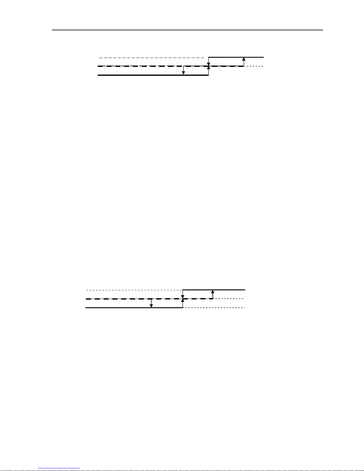
(1) While changing from Cool mode to Sleep mode, one hour later, the operation Temp.=ST+1°C,
another one hour later, the operation Temp.=ST+2°C,after then the temperature has no changed
anymore.
7
(2) When changing from Heating mode to Sleep mode, one hour later, the operation Temp.= ST-1°C,
another one hour later, the operation Temp.=ST-2°C,after then no changed anymore.
3) The machine will automatically shut up after running 10 hours under sleep mode.
When Timer ON and Sleep mode are implemented at the same time, the Sleep mode can not be
functioned.
7. Timer function
The timer can preset between 10min to 24h, when the time set less than “10” hours, the displayed
time shown by 0.5 hour as the unit, when the time set more than or equal to “10” hours, the
displayed time shown by 1 hour as the unit.
8. Emergency switch (ON/OFF)
1) When stand-by, to operate by pressing the emergency switch as follows:
Press the emergency switch within 3 seconds, release emergency switch while the buzzer rings once,
the machine goes into Cooling mode. If the buzzer rings twice while release emergency switch,
Heating mode is selected. To press the Emergency switch while A/C is on, the buzzer rings once and
then A/C will shut down.
2) The machine runs mandatorily as selected mode within 30min when Emergency operated,
meanwhile indoor fan motor runs in high-speed, and stepping vane swinging as well. 30min later
the A/C goes into automatic mode under the same operation manner, the set temperature to be
23°C, and the rotate speed of indoor fan motor automatic control, stepping vane swinging all the way.
3) To press the emergency button when the A/C goes on operation, then the machine runs into
stand-by.

Air Conditioner Service Manual
10
4) Under emergency operation, the function of compressor’s time-delay protection, Anti-frosting
protection in cooling mode, Overheating protection in heating mode, sensor fault protection and
defrost operate are effective.
5) Under emergency operation, once effective signal from remote controller received, the A/C
exits form of emergency mode without delay, and operates according to the setting value from remote
controller immediately.
9. Auto-restart function
1) The PCB retains the setting parameters in case of power off. When the power supply is resumed,
the machine, which has been started up the power-off memory function, is able to restore into the
original running state automatically.
To press the emergency button and power on the unit, and hold on for10 seconds, The buzzer
2) will ring three times, after this operation, the auto restart function activated.
3) To close auto restart function while it is activated, repeat process as above 2), the buzzer will ring
four times.
10. Protection / Failure code
10.1 Protection
1) Compressor’s protection:
a. The PCB which with Auto-restart function, once it is activated, the compressor goes along 3min
delay protection when power on, otherwise the compressor without this protection even when the PCB
is power-on.
b . The compressor’s 3 min interval protection: the compressor can’t start-up until it stops 3 min later.
(except for the defrosting process).
c. .After the compressor started, it’s operation state remains the same within 3 min even when ST, RT
variation.
2) Anti-frosting protection of indoor evaporator (Cooling mode):
If IPT≤0°C detected in consecutive 3 min, compressor and outdoor fan motor to be stopped operation,
indoor fan motor runs at high-speed forcibly; if IPT≥5°C detected 3min later, then outdoor fan motor
and compressor will start up, and indoor fan motor restores to it’s original state.
3) Overheating protection (Heating mode):
If IPT≥55°C, the outdoor fan motor: OFF.
If IPT≥65°C, the compressor: OFF, and indoor fan motor runs at
high-speed forcibly.
When IPT≤48°C, the outdoor fan motor and the compressor start up, indoor fan motor restores to it’s
original state.
4) Cold air prevention (Heating mode):
This function is intend to prevent cold air from being discharged when the heating operation starts or
when defrosting.
a.
When running into the heating mode, once the compressor fails to comply with the start-up
conditions, the fan speed is regulated according to the coil temperature within 2 min, 2 min later the
indoor fan motor stops. If the compressor starts up within 2 min, then operating according to Figure 5.
Under heating process, while the compressor stop (including stopping for protection), the fan motor’s
operation (including stopping the indoor fan motor) is regulated according to the coil temperature
within 1min, 1min later the fan will be stopped forcibly.

Air Conditioner Service Manual
11
b. When the indoor fan motor running at a low-speed under cold air prevention operation, once
auxiliary electric heating works, the vane immediately withdraws from the cold air prevention location
and turn back to normal vane angle. While auxiliary electric heating stops, indoor fan motor goes on to
run at low-speed accordingly, the vane turns to cold air prevention location
Figure 5 Cold air prevention
10.2 Failure code
The following table shows the fault protections.
When failures happens, the PCB alarms and buzzer rings three times, Failure code shows on
display board, and the PCB operates protection procedures.
Failure code: For the machine with LED display (88), the code shows on LED, for machine without
LED, the code reflects by the running light.
Failure Running Light Flash LED Display (88)
RT Sensor Failure Once / cycle E1
IPT Sensor Failure Twice / cycle E2
Outdoor unit protected 5 times / cycle E5
While failure happens, the code displayed statically, if there are several failure codes reported at the
same time, then failure codes appears by turns every eight seconds correspondingly.
6
a. Sensor’s failure protection: when the sensor tested temperature out of the range ---
50°C≤T≤110°C, sensor failure is determined.
Once RT and/or IPT sensor failure appears, the compressor stops, and indoor and outdoor fan
motors shut off. Remote controller doesn’t response to any signal except for
shutdown. During failure
the machine can run in fan mode. After the failure is settled, the PCB restores to standby status.
7
b. Outdoor unit protected. When the outdoor PCB has checked the high pressure, high current or the
3-phase mistake, the compressor stops, indoor and outdoor fan motors shut off. When the protected
relieve, the machine start again.
Set fan speed
Temperature dropping
Temperature rising
Stop the fan motor
Stop the fan motor
25°C
34°C
27°
23°C
Set fan speed
32°C

Air Conditioner Service Manual
12
5. WIRING DIAGRAM
MODEL: TFC-24HRA/TOC-24HNA
INDOOR UNIT:
OUTDOOR UNIT

Air Conditioner Service Manual
13
MODEL: TFC-48HRA/TOC-48HSA
INDOOR UNIT
FM
~
OUTDOOR UNIT

Air Conditioner Service Manual
14
6. EXPLOSION VIEW AND PARTS
EXPLOSION VIEW
Mode: TFC-24HRA, TFC-48HRA
INDOOR UNIT:
12
25 2826 27 29 30
23
24
22
21
20 19 1718 16 15 14 13
373231 33 34 35 36 1
11 10 89
3
2
4
7
5
6

Air Conditioner Service Manual
15
Parts List
Indoor Unit- TFC-24HRA
No.
Part No.
Part Name
Q’ty
Remark
1
210701315
Inside Base
1
2
1080510051AA
Right Plate
1
3
1080510067
Back Plate
1
4
1200710101
Rubber Water Drainage
1
5
1080510052AA
Left Plate
1
6
1110050531
Evaporator
1
7
1080520226
Top Plate
1
8
210702134
Pipe Cover
2
9
1070520508
Water Drainage
1
10
1150720004
Out Blow Casing Foam
1
11
1150720005
Heat insulation board
2
12
1070520106
Vertical Vane
5
13
1170010008
Synchronization Motor
1
14
1070710418
Horizontal Vane
6
15
1070710417
Up Panel
1
16
1080520103
Middle Supporter
1
17
1080710302
Heat insulation board Cover
1
18
1090520136
Display PCB
1
19
1070710421
Display PCB Supporter
1
20
1070710014
Display PCB Cover
1
21
1070710424
Spring
1
22
1070710423
Button
1
23
1020710001
Ornamental Board
1
24
1070710414
Down panel
1
25
1070710010
Fastener
1
26
1070520147
Air Filter
1
27
1170230009
Indoor Sensor
1
28
1074060115
Lead Flow Circle
1
29
1080520218
Inside Electrical Box Cover
1
30
1070010019AA
Centrifugal Fan
1
31
1170240002
Transformer
1
32
1170050002
Indoor Motor
1
33
1170100027A
Fan Motor Capacitor
1
34
1170200053
Terminal
1
35
210900265AN
Main PCB
1
36
1150520215
Volute Casing
1
37
1300521036
Inside Electrical Box
1
38
210900414A
Remote Controller
1
Not shown in Explosion view
39
210701101
Drainage hose
1
40
1170120009
Power supply cord
1
41
211300948GF
Indoor Carton
1

Air Conditioner Service Manual
16
Indoor Unit- TFC-48HRA
No.
Part No.
Part Name
Q’ty
Remark
1
1071200023
Inside Base
1
2
1081200114
Right Plate
1
3
1301200025
Back Plate
1
4
1204090101
Rubber Water Drainage
1
5
1081200116
Left Plate
1
6
1110050374
Evaporator
1
7
1071200024
Top Plate
1
8
210702134
Pipe Cover
2
9
1154090101
Water Drainage
1
10
1151200001
Out Blow Casing Foam
1
11
1214090113
Heat insulation board
2
12
1071200014
Vertical Vane
6
13
1170010008
Synchronization Motor
1
14
1071200012
Horizontal Vane
6
15
1071200011
Up Panel
1
16
1084090101
Middle Supporter
1
17
1090520136
Display PCB
1
18
1070710422
Display PCB Supporter
1
19
1070710014
Display PCB Cover
1
20
1070710424
Spring
1
21
1070710423
Button
1
22
1020710001
Ornamental Board
1
23
1071200021
Down panel
1
24
1070710016
Fastener
1
25
1070300003
Air Filter
1
26
1170230009
Indoor Sensor
1
27
1074090102
Lead Flow Circle
1
28
1084090113
Inside Electrical Box Cover
1
29
1070010004AA
Centrifugal Fan
1
30
1170240002
Transformer
1
31
1170030010
Indoor Motor
1
32
230901275
Fan Motor Capacitor
1
33
1170200058
Terminal
1
34
210900265BB
Main PCB
1
35
1154090102
Volute Casing
1
36
1081200155
Inside Electrical Box
1
37
210900414A
Remote Controller
1
Not shown in Explosion view
38
210701101AA
Drainage hose
1
39
1170120051
Power supply cord
1
40
1190510005KE
Indoor Carton
1

Air Conditioner Service Manual
17
MODEL: TAC-24CHFA/C
OUTDOOR UNIT:
10 11
8
9
6
754
20
14
12 13 15 16
17
18
19
32
21
22
24
23
25
26
1

Air Conditioner Service Manual
18
Outdoor Unit- TOC-24HNA
No.
Part No.
Part Name
Q’ty
Remark
1
1071990041
Back Grille
1
Optional
2
1081990038
Top Cover
1
3
1110060608
Condenser
1
4
1081990042
Outdoor Motor Supporter
1
5
1170040102
Outdoor Motor
1
6
1170120146AA
Propeller Fan
1
7
1081990040
Left Grille Supporter
1
8
210800277
Front Plate
1
9
1070251945
Fan Guard
1
10
3100060380
Compressor
1
11
1120110017
4-way Valve
1
12
1120700344
4-way Valve Assembly
1
13
1081990178
Base
1
14
1081990039
Right Plate
1
15
1120120024
Two-way Valve
1
16
1081990041
Valve Supporter
1
17
1120130037
Three-way Valve
1
18
1070350971
Electrical Box Cover
1
19
1074060118
Cable Clamp
1
20
1170200053
Terminal
1
21
1170100030A
Fan Motor Capacitor
1
22
1170100007B
Compressor Capacitor
1
23
1080010006
Capacitor Strip
1
24
1081990049
Electrical Parts Box
1
25
1174561801
AC Contactor
1
26
1120700345
Capillary Assembly
1
27
1174561802
Outdoor Defrost Sensor
1
Not shown in the explosion view
28
1190500707BLJ
Cabinet Carton
1

Air Conditioner Service Manual
19
OUTDOOR UNIT:
Mode: TOC-48HSA
This manual suits for next models
3
Table of contents
Other TCL Air Conditioner manuals

TCL
TCL TAC-07CHSA/XA71 User manual

TCL
TCL U-MATCH-R32 Series User manual

TCL
TCL iQool-C2MS12K12K Operating manual

TCL
TCL TAW Series User manual

TCL
TCL TCE-25CHSD User manual

TCL
TCL TCC-09C2HRH/DV User manual

TCL
TCL 5K-14K UM User manual

TCL
TCL TAC-07CS User manual

TCL
TCL AC12000E User manual

TCL
TCL TAC-09CHSD/XA31I User manual

TCL
TCL TAC-09CHSA/XP User manual

TCL
TCL iQool-3MS9K9K9K Operating manual

TCL
TCL iQool9B Operating manual

TCL
TCL TWAC-15CRA1/K8U User manual

TCL
TCL TAC-07CSK User manual

TCL
TCL FMA-09CHSD/DVI User manual

TCL
TCL TCLSS09 User manual

TCL
TCL TAC-09CHSD/XPI User manual

TCL
TCL TAC-24CF/E User manual

TCL
TCL TAC-09CSD/XAB1 User manual