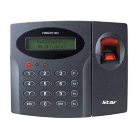
TDSi DIGIgarde PLUS User manual

TDSi
Unit 10 Concept Park
Innovation Close
Poole
Dorset
BH12 4QT, UK
Tel: +44 (0) 1202 723535
Fax: +44 (0) 1202 724975
DIGIgarde
PLUS
Fingerprint Reader and
Standalone Access Controller
User Guide
UM0071.GB Issue 4 13/05/2016
www.tdsi.co.uk

Foreword
ForewordForeword
Foreword
Copy right ©
2012 TDSi. All rights reserved.
Time and Data Systems International Ltd operate a policy of continuous
improvement and reserves the right to change specifications, colours or prices of
any of its products without prior notice.
Guarantee
GuaranteeGuarantee
Guarantee
For terms of guarantee, please contact your supplier.
Trademarks
TrademarksTrademarks
Trademarks
Copyright © 2012 Time and Data Systems International Ltd (TDSi). This document
or any software supplied with it may not be used for any purpose other than that for
which it is supplied nor shall any part of it be reproduced without the prior written
consent of TDSi.
Microsoft and Windows are registered trademarks of Microsoft Corporation.
All other brands and product names are trademarks or registered trademarks of
their respective owners.
Cautions and Notes
Cautions and NotesCautions and Notes
Cautions and Notes
The following symbols are used in this guide:
CAUTION! This indicates an important operating instruction that should be
followed to avoid any potential damage to hardware or property, loss of data,
or personal injury.
NOTE. This indicates important information to help you make the best use of this
product.

DIGIgarde PLUS User Guide
Last Change Copyright
©
2012 TDSi
13 May, 2016 Page i
Contents
ContentsContents
Contents
1.
1.1.
1. Introduction
IntroductionIntroduction
Introduction
................................
................................................................
................................................................
................................................................
................................................................
................................................................
................................................................
................................................................
........................................
................
........
1
11
1
1.1
About t is manual ............................................................................................................................................ 2
1.2
DIGIgarde PLUS layout ................................................................................................................................... 2
1.3
Basic concepts................................................................................................................................................... 3
1.3.1
User enrolment ............................................................................................................................... 3
1.3.2
User verification ............................................................................................................................. 3
1.3.3
T res old .......................................................................................................................................... 6
1.3.4
User ID numbers ............................................................................................................................. 6
1.3.5
Privilege levels ................................................................................................................................ 6
1.3.6
Log Definitions ................................................................................................................................ 7
1.4
How to use t e fingerprint sensor ............................................................................................................ 7
1.4.1
Correct positioning ........................................................................................................................ 7
1.4.2
Incorrect positioning ..................................................................................................................... 7
1.4.3
Common reasons for enrolment failure ................................................................................. 8
1.5
LED indication .................................................................................................................................................... 8
2.
2.2.
2. Installation
InstallationInstallation
Installation
................................
................................................................
................................................................
................................................................
................................................................
................................................................
................................................................
................................................................
..........................................
....................
..........
9
99
9
2.1
Unpacking ........................................................................................................................................................... 9
2.2
Fitting t e mounting plate ........................................................................................................................... 9
2.3
Connecting DIGIgarde PLUS ...................................................................................................................... 13
2.3.1
Preparing for connection .......................................................................................................... 13
2.3.2
Wiring guide .................................................................................................................................. 14
2.3.3
Power connection ....................................................................................................................... 15
2.3.4
Wiegand/Magnetic Clock Data to a compatible ACU ...................................................... 15
2.3.5
Alarm connection ......................................................................................................................... 16
2.3.6
Lock and Sensor connection .................................................................................................... 16
2.4
Communication .............................................................................................................................................. 18
2.4.1
TCP/IP .............................................................................................................................................. 18
2.4.2
RS232 .............................................................................................................................................. 19
2.4.3
RS485 .............................................................................................................................................. 19
2.5
Power on .......................................................................................................................................................... 20
2.5.1
Display layout ............................................................................................................................... 20
2.5.2
C eck In/C eck Out ..................................................................................................................... 20
2.5.3
First tasks ....................................................................................................................................... 20
3.
3.3.
3. User Setup
User SetupUser Setup
User Setup
................................
................................................................
................................................................
................................................................
................................................................
................................................................
................................................................
................................................................
.......................................
..............
.......
21
2121
21
3.1
Setting up Admin accounts ....................................................................................................................... 22
3.1.1
Privilege levels ............................................................................................................................. 22

Contents
DIGIgarde PLUS User Guide
Copyright
©
2012 TDSi Last Change
Page ii 13 May, 2016
3.1.2
Setting up an Admin account .................................................................................................. 22
3.2
Enrolment......................................................................................................................................................... 24
3.2.1
Enrolling a fingerprint ................................................................................................................ 25
3.2.2
Enrolling a password .................................................................................................................. 27
3.2.3
Enrolling a fingerprint and password ................................................................................... 28
3.3
Card enrolment............................................................................................................................................... 28
3.3.1
Enrol FP Card ................................................................................................................................. 29
3.3.2
Copy to Card .................................................................................................................................. 30
3.3.3
Register FP Card .......................................................................................................................... 30
3.3.4
Unregister FP Card ...................................................................................................................... 30
3.3.5
Delete FP Card .............................................................................................................................. 30
3.3.6
Copy Crd to Rdr ............................................................................................................................ 30
3.3.7
Move Rdr to Crd............................................................................................................................ 30
4.
4.4.
4. Device Settings
Device SettingsDevice Settings
Device Settings
................................
................................................................
................................................................
................................................................
................................................................
................................................................
..............................................................
............................................................
..............................
31
3131
31
4.1
T e Options menu ........................................................................................................................................ 31
4.1.1
Date/Time ...................................................................................................................................... 32
4.1.2
Language ........................................................................................................................................ 32
4.1.3
Date Format .................................................................................................................................. 33
4.1.4
Daylig t Saving Time ................................................................................................................. 34
4.1.5
Wiegand format ........................................................................................................................... 35
4.1.6
Advanced Options ....................................................................................................................... 36
4.2
Power management ..................................................................................................................................... 37
4.3
Communication options .............................................................................................................................. 37
4.4
Log options ...................................................................................................................................................... 38
4.5
LED mode ......................................................................................................................................................... 38
4.6
Data out type.................................................................................................................................................. 38
5.
5.5.
5. Standalone Mode
Standalone ModeStandalone Mode
Standalone Mode
................................
................................................................
................................................................
................................................................
................................................................
................................................................
...........................................................
......................................................
...........................
39
3939
39
5.2
User Access Verification Flowc art ....................................................................................................... 42
5.3
T e Access Control menu ........................................................................................................................... 43
5.4
Defining time patterns ................................................................................................................................ 44
5.4.1
Assigning a Time Pattern to a Group ................................................................................... 45
5.4.2
Assigning a Time Pattern to a User ...................................................................................... 45
5.5
User Access Options .................................................................................................................................... 45
5.5.1
Selecting t e User....................................................................................................................... 45
5.5.2
Assigning a user to a group ..................................................................................................... 46
5.5.3
Setting a user’s time patterns ................................................................................................ 46
5.5.4
C oosing a User’s Verification Met od ............................................................................... 47
5.6
Access combinations ................................................................................................................................... 47

Contents
DIGIgarde PLUS User Guide
Last Change Copyright
©
2012 TDSi
13 May, 2016 Page iii
5.7
Lock and door sense .................................................................................................................................... 48
5.8
Alarm .................................................................................................................................................................. 49
5.8.1
Resetting t e alarm .................................................................................................................... 49
5.9
Defining Duress options ............................................................................................................................. 50
5.10
Anti Passback ................................................................................................................................................. 51
5.10.1
Connection ..................................................................................................................................... 51
5.10.2
Set up ............................................................................................................................................... 52
5.10.3
Use .................................................................................................................................................... 52
6.
6.6.
6. System Information
System InformationSystem Information
System Information
................................
................................................................
................................................................
................................................................
................................................................
................................................................
......................................................
............................................
......................
53
5353
53
6.1
Sys Info menu ................................................................................................................................................. 53
6.2
Device Info menu .......................................................................................................................................... 54
6.3
Free Space Info menu .................................................................................................................................. 54
7.
7.7.
7. M
MM
Maintenance
aintenanceaintenance
aintenance
................................
................................................................
................................................................
................................................................
................................................................
................................................................
................................................................
................................................................
....................................
........
....
55
5555
55
7.1
Cleaning t e Keypad and Screen ............................................................................................................ 55
7.2
Cleaning t e Optical Sensor ...................................................................................................................... 55
8.
8.8.
8. Troubles ooting
Troubles ootingTroubles ooting
Troubles ooting
................................
................................................................
................................................................
................................................................
................................................................
................................................................
............................................................
........................................................
............................
57
5757
57
8.1
How to reset language back to Englis ................................................................................................ 57
8.2
How to reset t e unit .................................................................................................................................. 57
8.3
How to clear admin privileges .................................................................................................................. 57
8.4
W en fingerprint verification fails.......................................................................................................... 57
8.5
Communication failures .............................................................................................................................. 58
8.6
Display s ows “Please try again” w en no finger id presented for verification ................... 58
9.
9.9.
9. App
AppApp
Appendices
endicesendices
endices
................................
................................................................
................................................................
................................................................
................................................................
................................................................
................................................................
................................................................
......................................
............
......
59
5959
59
9.1
Menu structure ............................................................................................................................................... 59
9.2
Wiegand format ............................................................................................................................................. 62
9.2.1
Wiegand format ........................................................................................................................... 62
9.2.2
26-bit Wiegand format .............................................................................................................. 63

Contents
DIGIgarde PLUS User Guide
Copyright
©
2012 TDSi Last Change
Page iv 13 May, 2016
Figures
FiguresFigures
Figures
Figure 1
Removing t e security screw from t e base ...................................................................................................9
Figure 2
Mark t e fixing and cable ole positions ........................................................................................................ 10
Figure 3
Drilling t e oles: 6 mm for t e fixings and 8 mm for t e cable; fit t e wall plugs ...................... 10
Figure 4
Securing t e mount to t e mounting surface .............................................................................................. 11
Figure 5
Feeding t e cable and replacing t e reader .................................................................................................. 12
Figure 6
Securing t e DIGIgarde PLUS to t e mounting plate ................................................................................ 12
Figure 7
T e DIGIgarde PLUS cable bundle ..................................................................................................................... 13
Figure 8
Alarm connection ..................................................................................................................................................... 16
Figure 9
Fail-Open or Fail-Locked door connections.................................................................................................... 17
Figure 10
Connecting a single DIGIgarde PLUS to a PC using RS-232 .................................................................... 19
Figure 11
Example of a alf-duplex (2-wire) RS-485 network .................................................................................. 19
Figure 10
Access control options ........................................................................................................................................... 40
Figure 11
Example of Access combination use ................................................................................................................ 41
Tables
TablesTables
Tables
Table 1
Single factor verification modes ...........................................................................................................................4
Table 2
Two factor verification modes ..............................................................................................................................5
Table 3
T ree factor verification modes ...........................................................................................................................5
Table 4
Suggested T res old Settings ..............................................................................................................................6
Table 5
Cable Assignments .................................................................................................................................................. 14
Table 6
Et ernet RJ-45 connector pin number (From left to rig t) ...................................................................... 18
Table 7
Possible fingerprint enrolment errors .............................................................................................................. 26
Table 8
Card enrolment options ......................................................................................................................................... 29
Table 9
Options menu categories ...................................................................................................................................... 31
Table 10
Advanced options .................................................................................................................................................... 36
Table 11
Communication options ......................................................................................................................................... 37
Table 12
Log options ................................................................................................................................................................. 38
Table 13
Access Options menu ............................................................................................................................................. 43
Table 14
User Access Options menu ................................................................................................................................... 46
Table 15
Lock and door sense settings ............................................................................................................................. 48
Table 16
Duress Options .......................................................................................................................................................... 50
Table 17
Sys Info options ........................................................................................................................................................ 53
Table 18
Device Info settings ................................................................................................................................................ 54
Table 19
Free Space Info settings ....................................................................................................................................... 54
Table 20
Wiegand pulse c aracteristics ............................................................................................................................ 62
Table 21
26-bit Wiegand field definition .......................................................................................................................... 63

DIGIgarde PLUS User Guide
Last Change Copyright
©
2012 TDSi
13 May, 2016 Page 1
1.
1.1.
1. Introduction
IntroductionIntroduction
Introduction
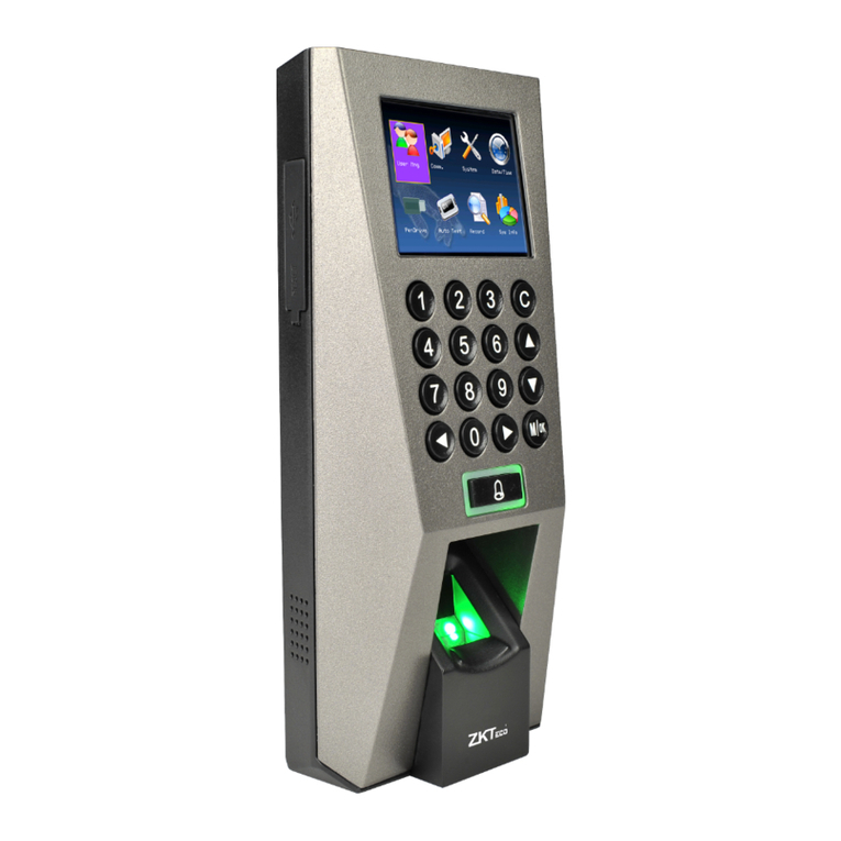
DIGIgarde PLUS is a combined fingerprint and card reader with integral backlit
keypad providing PIN, Mifare card and fingerprint authentication modes in an
attractive and cost-effective unit. With a high-resolution optical sensor and a fast
matching algorithm it is suitable for the control of ‘high traffic’ access points.
DIGIgarde PLUS units can also be used as Time & Attendance “clocking” stations.
Operates stand-alone or in conjunction with Access Controller.
Use the reader to control the door or alternatively integrate it into a full access
control system providing real-time event monitoring and central system
programming & T&A - Use the T&A functionality of the reader to allow users to
clock-in and clock out
1, 2 or 3 factor authentication
Gives you the flexibility to choose the level of security that matches your needs
Built in Mifare ™ Card reader
Allows storage of the fingerprint template on a smart card. Use the card for
other applications
Bypass card capability
Provides a means to grant access for those with badly damaged fingerprints
High speed matching algorithm
Quickly scans and processes the fingerprint maximising user convenience
Integrated with EXgarde
Manage the capture and distribution of templates from the same software used
to monitor and program your access control system.
Use the SDK to integrate DIGIgarde PLUS with other systems
External reader input
Connect a third-party reader to allow a fingerprint template to be associated
with a regular access control card
Dual-colour LED
Local programming interface
IP 65 Rated
For internal or external mounting
PoE powered
Removes the need to run a separate power cable to the reader
APB
Allows two readers to be used to help prevent security breaches
Custom message facility
Display user-specific messages on the reader to enhance user feedback
High resolution optical sensor
Particularly suited for scanning small fingerprints
TCP/IP, RS232 or RS485 connections
Supports a wide range of connection methods providing you with the connection
choice for your installation
2 line white-on-black LCD display
Enhances user feedback and allows for simple programming
Tamper protection
Be alerted immediately to the reader being removed from the wall.

Introduction
DIGIgarde PLUS User Guide
Copyright
©
2012 TDSi Last Change
Page 2 13 May, 2016
1.1
1.11.1
1.1 Abou
AbouAbou
About t is manual
t t is manualt t is manual
t t is manual
This manual describes the installation and configuration of DIGIgarde PLUS. It
describes the verification options and the standalone capabilities of the device. The
manual explains how to enrol users, set up groups and time patterns using the
DIGIgarde PLUS keypad, its internal operating system and the DIGIgarde PLUS
menu structure.
For information and instructions about the DIGIgarde PLUS software and how to
program networked units, please refer to the DIGIgarde PLUS Software Guide.
For information about developing software for the DIGIgarde PLUS, please refer to
the DIGIgarde PLUS SDK User Guide.
1.2
1.21.2
1.2 DIGIgarde PLUS
DIGIgarde PLUS DIGIgarde PLUS
DIGIgarde PLUS l
ll
layout
ayoutayout
ayout
Status LED
LED screen
▲OK and ▼buttons
Numeric Keypad
MENU button
ESC button
Fingerprint scanner
window
Smart card reader

Introduction
DIGIgarde PLUS User Guide
Last Change Copyright
©
2012 TDSi
13 May, 2016 Page 3
1.3
1.31.3
1.3 Basic
Basic Basic
Basic c
cc
concepts
onceptsoncepts
oncepts
This section describes the main concepts behind fingerprint identification using
DIGIgarde PLUS:
User Enrolment
User Verification
Match Threshold
User ID Numbers
Privilege Levels
1.3.1
1.3.11.3.1
1.3.1 User
User User
User enrolment
enrolmentenrolment
enrolment
You can enrol up to ten different fingerprints with each user ID.
When registering users, you should ideally enrol every finger and thumb. This
avoids problems with users forgetting which finger has been enrolled or being
unable to gain access because of any injury to the enrolled finger. At least two
fingerprints should be enrolled, left and right index fingers, for example, to provide
users with a ‘backup’.
1.3.2
1.3.21.3.2
1.3.2 User
UserUser
User
v
vv
verification
erificationerification
erification
Verification is the process of assessing the identity of a user attempting to gain
access through the DIGIgarde PLUS. This may involve checking some or all of the
following: user ID, fingerprint, password (or PIN) or smart card.
1:1 and 1:N f
1:1 and 1:N f1:1 and 1:N f
1:1 and 1:N fingerprint verification
ingerprint verificationingerprint verification
ingerprint verification
There are two basic types of fingerprint verification:
If the user is required to enter their ID, then the DIGIgarde PLUS is only
required to match the scanned fingerprint against the template registered under
the User’s ID. This is called 1:1 verification.
If a user is not required to input their ID, the DIGIgarde PLUS must then match
the scanned fingerprint against all the templates in its database. This is termed
1:N verification.
The verification process may also involve checks of an input password. DIGIgarde
PLUS shows whether the user has been identified successfully and stores the
result in its internal memory.

Introduction
DIGIgarde PLUS User Guide
Copyright
©
2012 TDSi Last Change
Page 4 13 May, 2016
Verification factors
Verification factorsVerification factors
Verification factors
The DIGIgarde PLUS Fingerprint reader supports single, dual and three factor
verification modes. Table 1, Table 2 and Table 3 provide a description of the
verification modes and shows how to use them. In the following table and in the
DIGIgarde PLUS menu, the following symbols are used:
/ means OR; +means AND
FP: Fingerprint; PW: Password (5-digit); ID: User ID (9-digit); RF: smart card
Table 1 Single factor verification modes
Mode Description
FP Only verify fingerprint using one of the following methods:
Enter ID; verify FP (1:1
verification)
Verify FP (1:N verification)
Present RF card; verify FP (1:1
verification)
ID Only verify the User ID
Enter ID through keypad
PW Only verify the password
Enter ID; enter PW
Present RF card and enter PW
RF Only verify the RF card
Present RF card
FP/PW Verify fingerprint OR password
ID and FP (1:1)
FP (1:N)
Enter ID; enter PW
Present RF card; enter PW
FP/RF Verify fingerprint or RF card
Enter ID; verify FP (1:1
verification)
Verify FP (1:N verification)
Present RF card
PW/RF Verify password or RF card
Present RF card
Enter ID; enter PW
FP/PW/RF Verify fingerprint or password or RF card
Enter ID; verify FP (1:1
verification)
Verify FP (1:N verification)
Enter ID; enter PW
Present RF card

Introduction
DIGIgarde PLUS User Guide
Last Change Copyright
©
2012 TDSi
13 May, 2016 Page 5
Table 2 Two factor verification modes
Mode Description
FP&ID Verify fingerprint and ID
Enter ID; verify FP (1:1
verification)
Present RF card; verify FP (1:1
verification)
FP&PW Verify the fingerprint and password
Verify fingerprint (1:N
verification) and enter PW
Enter ID; verify fingerprint (1:1
verification); enter PW
Present RF card; enter PW;
verify FP (1:1 verification)
FP&RF Verify the fingerprint and RF card
Present RF card and verify FP
(1:1 verification)
Verify FP (1:N verification and
present RF card)
Enter ID; verify FP (1:1
verification); present RF card
FP& ID / RF Verify the fingerprint and ID or Fingerprint and RF
Verify FP (1:N verification); enter
ID
Verify FP (1:N verification);
present RF card
Enter ID; verify FP (1:1
verification); enter ID
Enter ID; verify FP (1:1
verification); present RF card
Table 3 Three factor verification modes
Mode Description
FP&PW&RF Verify the fingerprint, password and RF card
Verify FP (1:N verification); enter
PW; present RF card
Enter ID; verify FP (1:1
verification); enter PW; present
RF card
Present RF card; enter PW;
verify FP (1:1 verification)
FP&ID&PW Verify the fingerprint, ID and Password
Enter ID; enter PW; verify FP
(1:1 verification)
Present RF card; enter ID; enter
PW; verify FP (1:1 verification)

Introduction
DIGIgarde PLUS User Guide
Copyright
©
2012 TDSi Last Change
Page 6 13 May, 2016
1.3.3
1.3.31.3.3
1.3.3 T res old
T res oldT res old
T res old
The quality of scanned fingerprints can be variable. This opens up the possibility of
two types of verification failure:
Valid users are rejected. This is called False Rejection. The False Rejection
Rate (FRR) is the probability that DIGIgarde PLUS will fail to identify an enrolled
user, or verify their legitimate identity.
An imposter is mistakenly accepted because of the similarity of their fingerprint
to that of a registered user. This is termed False Acceptance. The False
Acceptance Rate (FAR) is the probability that DIGIgarde PLUS will incorrectly
verify an individual or will fail to reject an impostor.
To minimize these effects, DIGIgarde PLUS uses a Threshold value to establish a
balance between False Acceptance and False Rejection. A high threshold value
reduces the chances of false acceptance but increase the probability of false
rejection. The default Threshold value is 35 for 1:N matching and 15 for 1:1
matching. Clearly, the chance of a false acceptance is much less when a user ID is
required since the DIGIgarde PLUS is only comparing the scanned fingerprint with
one template.
The threshold can be set for all users. Raising the threshold increases security,
while lowering it increases pass rate.
For a user whose fingerprint verification is difficult, you can either reduce the
threshold or adopt ID & Fingerprint verification (1:1 verification) – see page 45.
Table 4 Suggested Threshold Settings
FRR FAR 1:N 1:1
High Low 45 25
Middle Middle 35 15
Low High 25 10
1.3.4
1.3.41.3.4
1.3.4 User ID
User ID User ID
User ID n
nn
numbers
umbersumbers
umbers
During enrolment, DIGIgarde PLUS assigns a User ID Number to each user. This
ID can be used to call up the fingerprint template (1:1 verification) and/or password
each time that verification is requested.
A user can enter their ID number using the keypad or it can be called up from an
RF Card or Mifare Card.
1.3.5
1.3.51.3.5
1.3.5 Privil
PrivilPrivil
Privile
ee
ege
ge ge
ge l
ll
levels
evelsevels
evels
DIGIgarde PLUS recognizes four Privilege levels:
Users
People whose identity must be verified to gain access to a facility or to have
their attendance recorded.
Enrollers
DIGIgarde PLUS users who are authorized to enrol or delete users in the
system.
Managers
Additional powers except set advanced options and enrol manager or above
privilege users.

Introduction
DIGIgarde PLUS User Guide
Last Change Copyright
©
2012 TDSi
13 May, 2016 Page 7
Supervisors
Users with access to all DIGIgarde PLUS functions including system settings.
NOTE. During the initial setup, an Enroller may create Manager and Supervisor
accounts. Similarly, a Manager may create a Supervisor account. However, once
these accounts exist, only a Supervisor may create or edit Manager and
Supervisor accounts.
1.3.6
1.3.61.3.6
1.3.6 Log Definitions
Log DefinitionsLog Definitions
Log Definitions
The DIGIgarde PLUS records the following data:
Attendance Log Shows all attendance transactions.
Super Log Documents system changes.
1.4
1.41.4
1.4 How to use t e fingerprint
How to use t e fingerprint How to use t e fingerprint
How to use t e fingerprint sensor
sensorsensor
sensor
The quality of the fingerprint verification process depends on the ability of the user
to correctly position their finger on the scanning window. The finger should be
placed centrally and flat and not be moved during the 2-3 seconds of the scan.
1.4.1
1.4.11.4.1
1.4.1 Cor
CorCor
Correct positioning
rect positioningrect positioning
rect positioning
Finger aligned, centrally positioned and flat on the scanning window.
1.4.2
1.4.21.4.2
1.4.2 Incorrect positioning
Incorrect positioningIncorrect positioning
Incorrect positioning
Too far to one side/not central Raised finger/not flat on scanning window
Finger not fully on window Finger side on or at an angle

Introduction
DIGIgarde PLUS User Guide
Copyright
©
2012 TDSi Last Change
Page 8 13 May, 2016
1.4.3
1.4.31.4.3
1.4.3 Co
CoCo
Common reasons for
mmon reasons for mmon reasons for
mmon reasons for enrolment
enrolmentenrolment
enrolment
failure
failurefailure
failure
This section lists some of the common reasons for enrolment failure
Problem Remedy
Finger is too dry or
dirty
Rub the finger in the palm of your hand to clean and
breathe onto the finger to moisten.
Finger applied too
lightly
Place a finger firmly and flat on the sensor surface.
Finger positioned
incorrectly
Your finger should cover most of the sensor window.
Finger removed or
moved during scan
Hold your finger still and do not slide it on the sensor
window until the verification process is complete
Injury or wear has
changed the fingerprint
pattern
If the problem occurs with 1:N verification, try 1:1
verification, if this is an available. Contact the
administrator. You may need to enrol another finger or
use a password verification method instead.
Enroll
EnrollEnroll
Enroller’s
er’ser’s
er’s
guidelines
guidelinesguidelines
guidelines
When enrolling, we recommend you enrol users with their left or right index or
middle finger. Check the fingers for any injuries or wear.
If the user’s fingers are small, it may be preferable to use a thumbprint.
Few people’s fingerprint quality is too poor to verify but in difficult cases it is
advisable to use an ID & fingerprint verification method with the threshold reduced
accordingly. In extreme cases, use password verification to avoid fingerprint
verification problems.
1.5
1.51.5
1.5 LED indication
LED indicationLED indication
LED indication
The DIGIgarde PLUS unit has a red/green status LED in its top-left corner. This
provides information about the verification process.
Normal Red light flashes
Verification failure Red light on constant for 3 second
Verification successful Green light constant for duration of ‘Lock Open’ state.

DIGIgarde PLUS User Guide
Last Change Copyright
©
2012 TDSi
13 May, 2016 Page 9
2.
2.2.
2. Install
InstallInstall
Installation
ationation
ation
2.1
2.12.1
2.1 Unpacking
UnpackingUnpacking
Unpacking
Carefully unpack the DIGIgarde PLUS. The box contains the following:
DIGIgarde PLUS unit
CD with operating software, this manual, SDK software.
Mounting template
Quick start guide
Cable assembly
Ferrite ring
Tool for security screw
To install and operate the DIGIgarde Plus software, please refer to the DIGIgarde
PLUS Software Guide.
Fixing plugs and screws
Suppression diode
2.2
2.22.2
2.2 Fitting t e mounting pl
Fitting t e mounting plFitting t e mounting pl
Fitting t e mounting plate
ateate
ate
Fixing plugs and screws are supplied for mounting into brick or concrete. For
mounting onto other materials, please obtain suitable fixings for that material.
1. Using the tool supplied, remove the security screw from the bottom of the
reader. Remove the mount (rear cover) from the reader.
Figure 1 Removing the security screw from the base

Installation
DIGIgarde PLUS User Guide
Copyright
©
2012 TDSi Last Change
Page 10 13 May, 2016
2. Position the mounting plate against the wall or door frame and, using a
pencil, mark the positions of the three holes.
Figure 2 Mark the fixing and cable hole positions
CAUTION! Check for internal pipes and wires.
3. Drill two 6 mm holes for the wall fixings and a single 10 mm hole for the
cable. Fit the wall plugs into the 6 mm holes.
Figure 3 Drilling the holes: 6 mm for the fixings and 8 mm for the cable; fit the
wall plugs

Installation
DIGIgarde PLUS User Guide
Last Change Copyright
©
2012 TDSi
13 May, 2016 Page 11
4. Place the mounting plate on the wall and secure it in position with the
screws. Use a sprit level to ensure that the mounting plate is true.
Figure 4 Securing the mount to the mounting surface
5. Ensure that the anti-tamper magnet is in position below the cable access
hole.
Anti-tamper
magnet

Installation
DIGIgarde PLUS User Guide
Copyright
©
2012 TDSi Last Change
Page 12 13 May, 2016
6. Feed the cable into the wall and hook the top of the DIGIgarde PLUS onto
the mount.
Figure 5 Feeding the cable and replacing the reader
7. Lower the DIGIgarde PLUS into place and fit the security screw into the
bottom of the unit. Tighten the screw only sufficiently to retain the main
housing against the back plate.
CAUTION! Do not over-tighten the screw.
Figure 6 Securing the DIGIgarde PLUS to the mounting plate
8. Fit the supplied ferrite ring around the wire bundle for EMC protection (see
Figure 7).

Installation
DIGIgarde PLUS User Guide
Last Change Copyright
©
2012 TDSi
13 May, 2016 Page 13
2.3
2.32.3
2.3 Connecting
Connecting Connecting
Connecting DIGIgarde PLUS
DIGIgarde PLUSDIGIgarde PLUS
DIGIgarde PLUS
This section describes the connection of DIGIgarde PLUS to access control units,
other DIGIgarde PLUS units, door locks and sensors, alarms and a PC.
2.3.1
2.3.12.3.1
2.3.1 Preparing for connection
Preparing for connectionPreparing for connection
Preparing for connection
The items required for setup:
DIGIgarde PLUS complete with connection cable.
Magnetic ring for EMC protection (see below).
A suitable power supply with an output voltage of 10 to 14 VDC capable of
supplying 500 mA (peak). Note that the power supply from the access
control unit can be used if it is capable of providing a peak of 500 mA.
Optional - A TDSi access control unit or other suitable controller featuring a
Wiegand input port.
CAUTION! Please read this section carefully as incorrect wiring could cause
irreparable damage to DIGIgarde PLUS and invalidate the warranty. Check all
wiring before connecting power to the unit. Ensure the correct supply
voltage is set before powering DIGIgarde PLUS and connected devices.
Figure 7 The DIGIgarde PLUS cable bundle with ferrite ring

Installation
DIGIgarde PLUS User Guide
Copyright
©
2012 TDSi Last Change
Page 14 13 May, 2016
2.3.2
2.3.22.3.2
2.3.2 Wiring guide
Wiring guideWiring guide
Wiring guide
DIGIgarde PLUS can be connected to other devices (access control units, lock,
door sensor, alarm, host PC etc) through the colour-coded and labelled connection
cables. In addition to the connections described in Table 5, there is also a pre-
configured RJ-45 connector.
Table 5 Cable Assignments
Label Wire Colour Signal Description
Power Black 0V Power GND
Red +12V Power Input
WG IN
Black GND GND
White WD0-IN Wiegand Input, Data 0
Green WD1-IN Wiegand Input, Data 1
WG OUT
Yellow WD0-OUT Wiegand Output, Data 0
White WD1-OUT Wiegand Output, Data 1
Black GND Wiegand GND
Blue LED LED
Lock
White SENSOR Door Sensor power
Black GND Door Sensor ground
Grey BUTTON Egress button
Blue NO1 Normally Open
Red COM1 Common
Yellow NC1 Normally Closed
Alarm Orange ALARM NO2 Alarm (Normally Open)
Green ALARM COM2 Alarm (Common)
RS485-2 Blue RS-485A-2 RX+, RS-485-2 level
Yellow RS-485B-2 RX-, RS-485-2 level
RS232
Black RS-232 0V RS-232 0V
Grey RS-232 RX Receive Data, RS-232C level
Purple RS-232 TX Transmit Data, RS-232C level
RS485-1
Blue RS-485A-1 RX+, RS-485-1 level
Yellow RS-485B-1 RX-, RS-485-1 level
Black GND RS-485 GND
RS485RES
Brown RS-485RES Link wires to provide
termination resistor
(see page 19).
Brown RS-485RES
NOTE. RS232 and RS485 connections are not available on current build.
Other manuals for DIGIgarde PLUS
1
Table of contents
Other TDSi IP Access Controllers manuals
