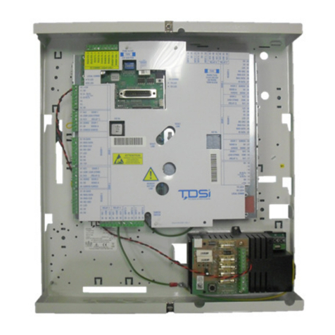
TDSi SOLOgarde User manual

User
UserUser
User
Manual
ManualManual
Manual
SOLOgarde
Stand Alone Access Control System
To Register your Product,
To Register your Product, To Register your Product,
To Register your Product,
Visit http://www tdsi
Visit http://www tdsiVisit http://www tdsi
Visit http://www tdsi-
--
-product
productproduct
product-
--
-registration co uk
registration co ukregistration co uk
registration co uk


HELP US TO HELP YOU
HELP US TO HELP YOUHELP US TO HELP YOU
HELP US TO HELP YOU
Every effort has been made to provide you with error free information However if you do find any inaccuracies or feel
that some additional information would be useful in this manual then we would like to hear from you Please copy and
complete the form below and fax it back to us on +44 (0)1202 724975 marked for the attention of ‘TDSi
TDSiTDSi
TDSi
Marketing
Marketing Marketing
Marketing
Department
DepartmentDepartment
Department’ or post it to:
TDSi
Unit 10 Concept Park
Innovation Close
Poole
Dorset
BH12 4QT, UK
Alternatively e-mail it to: marketing@tdsi co uk
User
User User
User Manual Improvement Form
Manual Improvement FormManual Improvement Form
Manual Improvement Form
Manual
Manual Manual
Manual №
UM0028 Issue
IssueIssue
Issue
2
About You
About YouAbout You
About You
N
NN
Name
ameame
ame
Company
CompanyCompany
Company
Main Company Activity
Main Company ActivityMain Company Activity
Main Company Activity
Address
AddressAddress
Address
Telephone Number
Telephone NumberTelephone Number
Telephone Number
E
EE
E-
--
-mail Address
mail Addressmail Address
mail Address
Your Comments
Your CommentsYour Comments
Your Comments
Please provide full description of the error or your suggested improvement, including page
and section numbers
Thank you,
Thank you,Thank you,
Thank you,
TDSi Marketing Team
Log
Log Log
Log ID
IDID
ID
DL
DLDL
DL


NOTICES
NOTICESNOTICES
NOTICES
Manufacturers Details
Manufacturers DetailsManufacturers Details
Manufacturers Details
This product is designed and supplied by:
Time and Data Systems International Ltd (TDSi)
Unit 10 Concept Park
Innovation Close
Poole
Dorset
BH12 4QT, UK
Telephone: +44 (0)1202 723 535
Fax: +44 (0)1202 724 975
E-mail: info@tdsi co uk
Web: http://www tdsi co uk
Copyright Notice
Copyright NoticeCopyright Notice
Copyright Notice
Copyright © 2008 Time and Data Systems International Ltd (TDSi) This document or any
software supplied with it may not be used for any purpose other than that for which it is
supplied nor shall any part of it be reproduced without the prior written consent of TDSi
TDSi Policy
TDSi PolicyTDSi Policy
TDSi Policy
Time and Data Systems International Ltd operate a policy of continuous improvement
and reserves the right to change specifications, colours or prices of any of its products
without prior notice

Table of Figures 6
1
Overview 7
2
Controller 8
2 1
Preparing the Controller for Installation 8
2 2
Installation of the Controller 9
2 2 1
Surface Mounting 9
2 2 2
Electrical Box Mounting 9
2 2 3
General Installation 9
2 3
Commission and Test of the Controller 15
2 4
Completing the Installation 16
3
Operating SOLOgarde 17
3 1
Adding Cards to SOLOgarde 17
3 1 1
Adding Cards using the Card Pack Master Card 17
3 1 2
Adding Subsequent Card Packs 17
3 1 3
Adding Cards using the Hand-Held Programmer 18
3 2
Editing Cards 22
3 2 1
Editing a Single Card 22
3 2 2
Editing a Block of Cards 23
3 3
Deleting Cards 25
3 3 1
Deleting a Single Card 25
3 3 2
Deleting a Block of Cards 25
3 4
Alarm Features 26
3 4 1
Alarm Output 26
3 4 2
Door Forced Alarm 26
3 4 3
Tamper Alarm 27
3 4 4
Duress Alarm
1
27
3 4 5
Input Voltage Alarm 27
3 4 6
Clearing an Alarm Condition 27
4
The SOLOgarde Hand-Held Programmer 28
4 1
Preparing the SOLOgarde Hand-Held Programmer for Operation 28
4 2
SOLOgarde Hand-Held Programmer Operational Overview 28
4 2 1
Navigating the Menu System using the Navigation Keys 29
4 2 2
Navigating the Menu System using the Shortcut Keys 29
4 2 3
Navigating the Menu System Using the Shortcut Keys 30
4 3
Switching Off the SOLOgarde Hand-Held Programmer and Disconnecting 30
5
Programming SOLOgarde 31
5 1
Controller Functions 31
5 1 1
Silent Mode 31
5 1 2
Door Relay Hold Time 31
5 1 3
Changing the Controller Password 32
5 1 4
Resetting the SOLOgarde Controller 32
5 2
Engineering and Installation Tools 34
Appendix 1 – SOLOgarde Hand-Held Programmer Menu Structure 36
Appendix 2 – Fault Finding 37
Table of Figures
Table of FiguresTable of Figures
Table of Figures
Figure 1 - SOLOgarde Control Unit 7
Figure 2 - SOLOgarde Control Unit (Terminal Label Removed) 7
Figure 3 – General Wiring Arrangement for SOLOgarde 10
Figure 4 – Wiring the Power Supply Unit 11
Figure 5 – Wiring the Read-In Reader (Main Connections) 11
Figure 6a – Wiring the Read-In Reader (Communications) 11
Figure 6b - Wiring Back Box USB Connector………………………………………………………………………………………………………………………………………………… 11
Figure 7 – Wiring the Second (Optional) Reader 12
Figure 8 – Wiring the Door Lock (Fail Safe Operation) 12
Figure 9 – Wiring the Door Lock (Fail Secure Operation) 13
Figure 10 – Wiring an External Alarm Device 13
Figure 11 – Wiring the Door Contact 13
Figure 12 – Wiring a Request to Exit Button 14
Figure 13 – Wiring a Tamper Switch 14
Figure 14 – Wiring a Clock to the Timer Input 14
Figure 15 – Hand-Held Programmer Menu Structure 36

1
11
1Overview
OverviewOverview
Overview
Thank you for purchasing SOLOgarde, a stand alone door access control system SOLOgarde comes with some innovative
features that greatly simplify both the installation and use of the product
Provided that it is installed correctly, SOLOgarde will provide many years of trouble-free operation To ensure this, please
read and understand this manual fully
Figure
Figure Figure
Figure 1
11
1
-
--
-
SOLOgarde Control Unit
SOLOgarde Control UnitSOLOgarde Control Unit
SOLOgarde Control Unit
Figure
Figure Figure
Figure 2
22
2
-
--
-
SOLOgarde Control Unit (Terminal Label Removed)
SOLOgarde Control Unit (Terminal Label Removed)SOLOgarde Control Unit (Terminal Label Removed)
SOLOgarde Control Unit (Terminal Label Removed)
1 Terminal Label
2 Activity LEDs (Red and Green)
3 Relay Active LED (Green)
4 Terminal Label Mounting Post
5 Alarm LED (Green)
6 Spring-Loaded Terminal Block
7 Door Sense Bypass Link (JP5)
8 Reset Link (JP4)
9 Sounder
10 Alarm Output Link (JP2)
11 Relay
Table
Table Table
Table 1
11
1
-
--
-
Key to SOLOgarde Controller Layout
Key to SOLOgarde Controller LayoutKey to SOLOgarde Controller Layout
Key to SOLOgarde Controller Layout
1
2
3
4
5
6
6
7
8
6
9
11
10

2
22
2Controller
ControllerController
Controller
The controller is contained within a single Printed Circuit Board Assembly (PCBA)
and features:
A relay for controlling doors or signalling to other equipment
An on-board sounder
Light Emitting Diodes (LEDs) for indication of activity, relay and alarm
operation
Jumper headers for enabling controller features
Spring-loaded connection terminals
Terminal label showing all connections to the controller
2 1
2 12 1
2 1 Preparing the Controller for Installation
Preparing the Controller for InstallationPreparing the Controller for Installation
Preparing the Controller for Installation
The controller is supplied ready for installation Remove all packaging and check the contents of the kit as follows:
SOLOgarde Control PCB (1 off)
Lock Suppression Diode (1 off)
Foam Spacer (for electrical surface box mounting) (2 off)
Quick Start Guide (1 off)
In addition to the controller board supplied, the following items for mounting and installation will also be required:
1-Gang Electrical Surface Box at least 32 mm deep together with a blank cover plate OR
OROR
OR for the EXprox Reader version
the Wall Mounting Box with USB Connector P/No 4262-1600
Alternative fixings 3 mm self-adhesive feet (3 off)
Wire strippers
Wire Cutters
Screwdriver

2 2
2 22 2
2 2 Installation of the Controller
Installation of the ControllerInstallation of the Controller
Installation of the Controller
Install the SOLOgarde controller as follows:
Choose a suitable mounting position for the controller This should be on the secure side of the door If the SOLOgarde
controller is to be mounted in the Electrical Surface box or Wall Mounting Box with USB Connector, fit this to the wall
2 2 1
2 2 12 2 1
2 2 1 Surface Mounting
Surface MountingSurface Mounting
Surface Mounting
When mounting using self-adhesive feet, choose a suitable flat surface to mount
the controller onto Fit one foot to each of the three elongated slots in the
underside of the controller board Peel the liners from the feet and secure the
controller board into the required position Now route the reader, door and
service cables to the SOLOgarde controller and go to section 2 2 3 for general
installation instructions
2 2 2
2 2 22 2 2
2 2 2 Electrical
Electrical Electrical
Electrical or Wall Mounting
or Wall Mounting or Wall Mounting
or Wall Mounting Box Mounting
Box MountingBox Mounting
Box Mounting
Route the cable from the reader to the controller When mounting in an Electrical
Surface Box mounting pass the cables either through the back or side of the box
When mounting in the Wall Mounting Box with USB Connector pass the cables
through the back or side of the box and connect any reader screen braids to the
earth terminal
Now go to section 2 2 3 for general installation instructions
2 2 3
2 2 32 2 3
2 2 3 General Installation
General InstallationGeneral Installation
General Installation
Prepare the wiring by stripping approximately 10 mm of insulation from the
conductors Twist the exposed conductors to ensure that the ends are neat and
that there are no stray strands of wire
Hint: If more than one wire is to be installed in one terminal, twist the exposed conductors
Hint: If more than one wire is to be installed in one terminal, twist the exposed conductors Hint: If more than one wire is to be installed in one terminal, twist the exposed conductors
Hint: If more than one wire is to be installed in one terminal, twist the exposed conductors
together to ease insertion of the wires into the terminal
together to ease insertion of the wires into the terminaltogether to ease insertion of the wires into the terminal
together to ease insertion of the wires into the terminal
Make the reader connections as shown in Figure 3 to 14 To make a connection
use a suitable tool (such as a terminal screwdriver) to press down the orange
lever for the appropriate terminal Ensure that the lever is pressed all the way
down to ensure that the wire guard within the terminal is fully open
10
mm

Insert the stripped wire into the terminal Ensure that it is fully inserted
Release the lever To test to see if the connection has been made correctly, look
at the lever If it is slightly depressed, then the connection has been made
successfully Perform a final test by gently pulling on the wire It should not
come out
Fit the links according to the installation requirements
Fit the Sense
SenseSense
Sense link (marked JP5
JP5JP5
JP5) if a door sense is not being used If the door
sense is being used then leave the Sense
SenseSense
Sense link off
For positive alarm action (i e the Alarm output is to be taken to +12 V during
an alarm condition) fit a jumper to the link marked JP2
JP2JP2
JP2
To change a link (JP2 shown in this example), take the jumper from ‘parked’
position on the link (it will be placed on one pin only) and place it so that it is
positioned on both of the link pins
Figure
Figure Figure
Figure 3
33
3
–
––
–
General Wiring Arrangement for SOLO
General Wiring Arrangement for SOLOGeneral Wiring Arrangement for SOLO
General Wiring Arrangement for SOLOgarde
gardegarde
garde
Reader
Second Reader (Opt
ional)
SOLOgarde
Controller
Power In
JP2
JP5

Figure
Figure Figure
Figure 4
44
4
–
––
–
Wiring the Power Supply Unit
Wiring the Power Supply UnitWiring the Power Supply Unit
Wiring the Power Supply Unit
Power Supply
Power SupplyPower Supply
Power Supply
Wire a suitable 12V DC power supply between the
VCC In
VCC InVCC In
VCC In and 0V
0V0V
0V
terminals of the SOLOgarde
controller
Figure
Figure Figure
Figure 5
55
5
–
––
–
Wiring the Read
Wiring the ReadWiring the Read
Wiring the Read-
--
-In Reader (M
In Reader (MIn Reader (M
In Reader (Main Connections)
ain Connections)ain Connections)
ain Connections)
Reader (Read
Reader (ReadReader (Read
Reader (Read-
--
-In)
In)In)
In)
Wire the thicker of the two SOLOgarde reader
cables OR
OROR
OR the 8 way cable of the EXprox reader to
the SOLOgarde controller terminal block marked
Reader 1
Reader 1Reader 1
Reader 1 as shown opposite If two readers are
to be installed this is the reader that controls
access from the unsecure area to the secure area
Note that the cable colours must match those
shown on the terminal label
Figure
Figure Figure
Figure 6
66
6a
aa
a
–
––
–
Wiring the Read
Wiring the ReadWiring the Read
Wiring the Read-
--
-In Reader (Communications)
In Reader (Communications)In Reader (Communications)
In Reader (Communications)
Mifare
MifareMifare
Mifare
Reader (Read
Reader (ReadReader (Read
Reader (Read-
--
-In) Communi
In) CommuniIn) Communi
In) Communications
cationscations
cations
Wire the thinner of the two SOLOgarde reader
cables to the SOLOgarde controller terminal block
marked Reader
ReaderReader
Reader as shown opposite, If two readers
are to be installed this is the reader that controls
access from the unsecure to the secure area
Note that the cable colours must match those
shown on the terminal label

Figure 6b
Figure 6b Figure 6b
Figure 6b –
––
–
Wiring
Wiring Wiring
Wiring Back Box USB Connector
Back Box USB ConnectorBack Box USB Connector
Back Box USB Connector
Wall M
Wall MWall M
Wall Mounting
ounting ounting
ounting Back Box USB Connector
Back Box USB ConnectorBack Box USB Connector
Back Box USB Connector
Wire USB connector cables to SOLOgarde
controller terminal block marked Reader
ReaderReader
Reader as shown
opposite, ensure USB connector cable screen and
drain wire are connected to the earth terminal
located in the wall mounting back box
Figure
Figure Figure
Figure 7
77
7
–
––
–
Wiring the Second (Optional) Reader
Wiring the Second (Optional) ReaderWiring the Second (Optional) Reader
Wiring the Second (Optional) Reader
Second Reader (Read
Second Reader (ReadSecond Reader (Read
Second Reader (Read-
--
-Out)
Out)Out)
Out)
Wire the thicker of the two SOLOgarde Reader
cables OR
OROR
OR the 8 way cable of the EXprox reader to
the SOLOgarde controller terminal block marked
Reader 2
Reader 2Reader 2
Reader 2 as shown opposite If two readers are
to be installed this is the reader that controls
access from the secure area to the unsecure area
Note that the cable colours must match those
shown on the terminal label
Figure
Figure Figure
Figure 8
88
8
–
––
–
Wiring the Door Lock (Fail Safe Operation)
Wiring the Door Lock (Fail Safe Operation)Wiring the Door Lock (Fail Safe Operation)
Wiring the Door Lock (Fail Safe Operation)
Door Lock
Door Lock Door Lock
Door Lock –
––
–
Fail Safe
Fail SafeFail Safe
Fail Safe
Connect the door lock between the +12 V supply
and the Com terminal Link the 0V and N/C
terminals
Note: A suppression diode MUST be fitted at
Note: A suppression diode MUST be fitted at Note: A suppression diode MUST be fitted at
Note: A suppression diode MUST be fitted at
the door lock Failure to do so may result in
the door lock Failure to do so may result in the door lock Failure to do so may result in
the door lock Failure to do so may result in
permanent irreparable damage to the
permanent irreparable damage to the permanent irreparable damage to the
permanent irreparable damage to the
controller
controllercontroller
controller
+12 V

Figure
Figure Figure
Figure 9
99
9
–
––
–
Wiring the Door Lock (Fail Secure Oper
Wiring the Door Lock (Fail Secure OperWiring the Door Lock (Fail Secure Oper
Wiring the Door Lock (Fail Secure Operation)
ation)ation)
ation)
Door Lock
Door Lock Door Lock
Door Lock –
––
–
Fail Secure
Fail SecureFail Secure
Fail Secure
Connect the door lock between the +12 V supply
and the Com terminal Link the 0V and N/O
terminals
Note: A suppression diode MUST be fitted at
Note: A suppression diode MUST be fitted at Note: A suppression diode MUST be fitted at
Note: A suppression diode MUST be fitted at
the door lock Failure to do so may result in
the door lock Failure to do so may result in the door lock Failure to do so may result in
the door lock Failure to do so may result in
permanent irreparable damage t
permanent irreparable damage tpermanent irreparable damage t
permanent irreparable damage to the
o the o the
o the
controller
controllercontroller
controller
Figure
Figure Figure
Figure 10
1010
10
–
––
–
Wiring an External Alarm Device
Wiring an External Alarm DeviceWiring an External Alarm Device
Wiring an External Alarm Device
External Alarm
External AlarmExternal Alarm
External Alarm
The Alarm output is capable of driving an external
alarm device up to 1A Connect the unit between
the Alarm + and Alarm – terminals Fit the link J
JJ
JP2
P2P2
P2
to supply the external device with power from the
SOLOgarde PCB
Figure
Figure Figure
Figure 11
1111
11
–
––
–
Wiring the Door Contact
Wiring the Door ContactWiring the Door Contact
Wiring the Door Contact
Door Sense
Door SenseDoor Sense
Door Sense
Wire a door contact (normally open type) between
the Sense
SenseSense
Sense and Common
CommonCommon
Common terminals Make sure that
the Door Sense Bypass Link jumper JP5 (circled) is
not fitted
+12 V

Figure
Figure Figure
Figure 12
1212
12
–
––
–
Wiring a Request to Exit Button
Wiring a Request to Exit ButtonWiring a Request to Exit Button
Wiring a Request to Exit Button
Request to Exit Button
Request to Exit ButtonRequest to Exit Button
Request to Exit Button
If using the SOLOgarde in single reader mode, fit a
Request to Exit button between the Egress
EgressEgress
Egress and
Common
CommonCommon
Common terminals
Figure
Figure Figure
Figure 13
1313
13
–
––
–
Wiring a Tamper Switch
Wiring a Tamper SwitchWiring a Tamper Switch
Wiring a Tamper Switch
Tamper
TamperTamper
Tamper
If a tamper switch is to be fitted, connect this
between the Tamper
TamperTamper
Tamper and Common
CommonCommon
Common terminals
Figure
Figure Figure
Figure 14
1414
14
–
––
–
Wiring a Clock to the Timer Input
Wiring a Clock to the Timer InputWiring a Clock to the Timer Input
Wiring a Clock to the Timer Input
Clock Timer Inpu
Clock Timer InpuClock Timer Inpu
Clock Timer Input
tt
t
If the Time Zone feature of SOLOgarde is to be
utilised, connect a timer between the Timer
TimerTimer
Timer and
Common
CommonCommon
Common terminals
Once all of the connections have been made, it commission and test SOLOgarde as described in section 2 3 of this manual

2 3
2 32 3
2 3 Commission and Test
Commission and TestCommission and Test
Commission and Test
of the Controller
of the Controllerof the Controller
of the Controller
Prior to using the SOLOgarde system, it is necessary to test and commission it
Ensure that the jumper links are fitted as required Apply power to the SOLOgarde controller
Check that the green Activity light is flashing It should indicate a double flash
every two seconds showing that the controller is running
If the alarm is sounding (indicated by three successive bleeps of the SOLOgarde
sounder every 2 seconds and the red Activity light flashing), check that the door
is not open The alarm will automatically silence after a period of 30 seconds
Alternatively, use the hand-held programmer to reset the alarm (refer to section
3 4 6 of this manual for details on how to do this )
If a hand-held programmer is available, connect this now Refer to section 4 2 on
how to use the hand-held programmer Also please read section 0, which
describes the Installation and Engineering features of the hand-held programmer
Release the door by either pressing the Request to Exit button (if fitted) or by
briefly connecting the Egress
EgressEgress
Egress terminal to the Common
CommonCommon
Common terminal using a length of
wire The following should occur:
You may hear an audible click from the relay
The LED marked relay is illuminated while the relay is operated (5 seconds)
The door is released

2 4
2 42 4
2 4 Completing the Installation
Completing the InstallationCompleting the Installation
Completing the Installation
Once commissioning and testing has been completed successfully, finalise the
installation by offer the SOLOgarde controller into the box face down
Remove the backing from the foam spacers and stick these to the rear of the
cover so that the fixing screws will pass through the centre of them
Fit the blank cover plate to the box and screw into position using the screws
supplied with the cover
SOLOgarde is now ready for use Refer to the rest of this manual on the programming and operation of the system

3
33
3Operating SOLOgarde
Operating SOLOgardeOperating SOLOgarde
Operating SOLOgarde
3 1
3 13 1
3 1 A
AA
Adding Cards to
dding Cards to dding Cards to
dding Cards to SOLOgarde
SOLOgardeSOLOgarde
SOLOgarde
(Mifare
(Mifare (Mifare
(Mifare Card
CardCard
Cards only)
s only)s only)
s only)
Once the SOLOgarde controller and reader has been successfully installed and switched on, it is ready to accept the
programming of cards
Cards can be added to the SOLOgarde controller in one of two ways Either the cards can be added by presenting the
Master Card supplied with the Card Pack to the SOLOgarde reader or using the hand-held programmer
3 1 1
3 1 13 1 1
3 1 1 Adding Cards using the Card Pack Master Card
Adding Cards using the Card Pack Master CardAdding Cards using the Card Pack Master Card
Adding Cards using the Card Pack Master Card
Each SOLOgarde Card Pack is supplied with a Master Card, which contains
information relating to the cards contained within that card pack The Master
Card shows the following information:
A: The Serial Number of the Master Card This allows easy identification of
the Master Card at a later date
B: The Start card number relating to this Master Card
C: The End card number relating to this Master Card
If this is the first time that the SOLOgarde is being used, there are no cards in the
memory of the unit and it is ready to accept programming of the first card pack
To load the card pack:
simply present the Master Card supplied with the card pack to the reader
The controller will emit a long bleep and the green LED on the reader will
illuminate for 1 second
All of the cards contained within that Card Pack are automatically validated in
the controller
Once done the system is now ready to use and the cards can be distributed to
the users
Hint: keeping records of the cards that are distributed will allow easy identification of users so that
Hint: keeping records of the cards that are distributed will allow easy identification of users so that Hint: keeping records of the cards that are distributed will allow easy identification of users so that
Hint: keeping records of the cards that are distributed will allow easy identification of users so that
cards can be
cards can be cards can be
cards can be deleted at a later dat
deleted at a later datdeleted at a later dat
deleted at a later date Please use the Record Sheet supplied
e Please use the Record Sheet suppliede Please use the Record Sheet supplied
e Please use the Record Sheet supplied
with the cards to ensure
with the cards to ensure with the cards to ensure
with the cards to ensure
that this information is recorded
that this information is recordedthat this information is recorded
that this information is recorded
The Record Sheet can also be downloaded in Microsoft Excel
The Record Sheet can also be downloaded in Microsoft Excel The Record Sheet can also be downloaded in Microsoft Excel
The Record Sheet can also be downloaded in Microsoft Excel
format from the TDSi website
format from the TDSi websiteformat from the TDSi website
format from the TDSi website
Note: it is essential that this Master Ca
Note: it is essential that this Master CaNote: it is essential that this Master Ca
Note: it is essential that this Master Card is kept in a safe place
rd is kept in a safe place rd is kept in a safe place
rd is kept in a safe place It will be needed
It will be neededIt will be needed
It will be needed
if you want to program further
if you want to program further if you want to program further
if you want to program further
card packs into the SOLOgarde controller
card packs into the SOLOgarde controllercard packs into the SOLOgarde controller
card packs into the SOLOgarde controller
memory
memorymemory
memory
3 1 2
3 1 23 1 2
3 1 2 Adding Subsequent Card Packs
Adding Subsequent Card PacksAdding Subsequent Card Packs
Adding Subsequent Card Packs
Once the first Master Card has been shown to the reader the controller records the details of this card Further cards can
be added to the system as follows Access to both the original Master Card and the Master Card from the Card Pack that
are to be added will be needed
Present the original Master Card to the SOLOgarde reader The controller will emit two bleeps and the red Activity LED
will flash twice The green LED on the reader will also start to flash indicating that Master Card from the new Card Pack
can be presented
Present the Master Card form the new Card Pack The controller will emit a long bleep and the green LED on the reader
will illuminate for 1 second indicating that the cards from the second pack have been validated in the controller
The additional card pack is now ready for use
Further card packs can be added in the same way, up to the maximum capacity of the controller
Master Card
1291604699
Number Range: 0000000001
0000000025
SOLOgarde TDSi
A
B
C

3 1 3
3 1 33 1 3
3 1 3 Adding Cards using the Hand
Adding Cards using the HandAdding Cards using the Hand
Adding Cards using the Hand-
--
-Held
Held Held
Held Programmer
ProgrammerProgrammer
Programmer
(Mifare or EXprox
(Mifare or EXprox (Mifare or EXprox
(Mifare or EXprox Cards
CardsCards
Cards)
))
)
The hand-held programmer provides a convenient method of adding a single card or blocks of card numbers
3 1 3 1
3 1 3 13 1 3 1
3 1 3 1 Adding a Single Card
Adding a Single CardAdding a Single Card
Adding a Single Card
Turn the hand-held programmer on and connect it to the bottom of the reader or
the USB socket on the Wall Mounting Box and log-in to the controller by entering
the 4-digit password followed by the *
**
* button For more details on logging-in and
the password feature, please refer to section 4 2 of this manual
Press the key until the Card
CardCard
Card option is highlighted (flashing) Press the *
**
* key to
select it
Ensure that the Add
AddAdd
Add option is highlighted and press the *
**
* key to select
With the Single
SingleSingle
Single option selected, press the *
**
* key to select
Either enter the card number using the numeric keypad or simply present the card
to be added to the reader The card number will automatically appear on the
programmer display Once the card number has been entered, press the *
**
* key to
store it
If the card is already in the memory the programmer will show this by Replace?
Replace?Replace?
Replace?
being displayed To overwrite the card information with the new data that is to
be entered, use the key to highlight OK
OKOK
OK and press the *
**
* key to replace the card
To abort the process, highlight Esc
EscEsc
Esc and press the *
**
* key
Hint
HintHint
Hint: it is not necessary enter the full number, for example for the card number 00485525 just
: it is not necessary enter the full number, for example for the card number 00485525 just : it is not necessary enter the full number, for example for the card number 00485525 just
: it is not necessary enter the full number, for example for the card number 00485525 just
485525 can be entered followed by the *
485525 can be entered followed by the *485525 can be entered followed by the *
485525 can be entered followed by the *
key
keykey
key
The programmer now displays a number of options that allow the properties of
the card to be tailored The first option is the card Mode
ModeMode
Mode Press the *
**
* key to view
and change the options for the card Mode
ModeMode
Mode These are:
Card
CardCard
Card
(the default setting) where the user is required to present only a card in
order to gain access
Crd+PIN
Crd+PINCrd+PIN
Crd+PIN where the user is required to present their card followed by a
Personal Identification Number (PIN) using the reader keypad
1
Crd+Code
Crd+CodeCrd+Code
Crd+Code where the user is required to present their card followed by a
global code using the reader keypad
1
Use the or keys to highlight your required card Mode
ModeMode
Mode and press the *
**
* key to
select it
Replace?
Esc OK
Mode
Time Grp
Number
00485525
Single
Block
Add
Delete
Card
Keypad

The next option is the Time Group
Time GroupTime Group
Time Group in which the user(s) are to be members of
Press the *
**
* key to view and change the options for the Time Group
TZ1
TZ1TZ1
TZ1 (the default setting) Members of the Time Zone 1 group are valid when
the Time
TimeTime
Time input is off (i e high or at +12 V)
TZ2
TZ2TZ2
TZ2 Members of the Time Zone 2 group are valid when the Time
TimeTime
Time input is on
(i e low or at 0 V)
TZ1 +TZ2
TZ1 +TZ2TZ1 +TZ2
TZ1 +TZ2 Members of the Time Zone 1 plus Time Zone 2 group are valid
regardless of the state of the Time input
Use the or keys to highlight your required Time Group
Time GroupTime Group
Time Group and press the *
**
* key
to select it
The final option is the card Type
TypeType
Type Press the *
**
* key to view and change the options
for the card Type
TypeType
Type
Standard
StandardStandard
Standard (the default setting) The lock time that has been set up in the
controller will apply to this card
DDA
DDADDA
DDA The lock time that will apply to the card will be double that of the lock
time set in the controller, allowing more time for the person to pass through
the door
Toggle
ToggleToggle
Toggle The card will toggle the state of the door relay This is particularly
useful for temporarily unlocking a door for example
a meeting room or
lecture theatre or setting
unsetting of an intruder panel
Use the or keys to highlight your required card Type
TypeType
Type and press the *
**
* key to
select it
Once all of the options have been set, it is time to validate the card Ensure that
the Validate
ValidateValidate
Validate option is highlighted (flashing) and press the *
**
* key
Confirm the entry by pressing the *
**
* key once again The controller will emit a
single bleep to indicate that programming of the card has been successfully
completed Once the card has been added to the system OK
OKOK
OK is displayed If the
display shows Mem Full
Mem FullMem Full
Mem Full then the controller memory is full Delete some unused
cards to make room for the new card(s) – refer to section 0 of this manual
Hint: if you want to u
Hint: if you want to uHint: if you want to u
Hint: if you want to use the default settings for each of the options card Mode, Time Group and
se the default settings for each of the options card Mode, Time Group and se the default settings for each of the options card Mode, Time Group and
se the default settings for each of the options card Mode, Time Group and
Type, once you have entered the card number, you can simply scroll down to the Validate option
Type, once you have entered the card number, you can simply scroll down to the Validate option Type, once you have entered the card number, you can simply scroll down to the Validate option
Type, once you have entered the card number, you can simply scroll down to the Validate option
(using the
(using the (using the
(using the
button) and press the * key to validate the card quickly
button) and press the * key to validate the card quicklybutton) and press the * key to validate the card quickly
button) and press the * key to validate the card quickly
1
certain versions only
Add
Confirm?
Validate
Mode
Type
Validate
Time Grp
Type

3 1 3 2
3 1 3 23 1 3 2
3 1 3 2 Adding a Block of
Adding a Block of Adding a Block of
Adding a Block of Cards
CardsCards
Cards
(Mifare
(Mifare (Mifare
(Mifare Cards
CardsCards
Cards
only)
only)only)
only)
Turn the hand-held programmer on and connect it to the bottom of the reader
and log-in to the controller by entering the 4-digit password followed by the *
**
*
button For more details on logging-in and the password feature, please refer to
section 4 2 of this manual
Press the key until the Card
CardCard
Card option is highlighted (flashing) Press the *
**
* key to
select it
Ensure that the Add
AddAdd
Add option is highlighted and press the *
**
* key to select
Choose the Block
BlockBlock
Block option by using the or keys When the option is
highlighted, press the *
**
* key to select it
Enter the S
SS
Start
tarttart
tart number of the block of cards to be added or present the card that
is at the beginning of the block to the reader, followed by the *
**
* key…
…followed by the End
EndEnd
End number of the block of cards to be added or present the
card number that is at the end of the block to the reader Press the *
**
* key when
completed
If the block of cards being added contains one that is already in memory the
programmer will show this by Replace?
Replace?Replace?
Replace? being displayed To overwrite the card
information with the new data that is to be entered, use the key to highlight
OK
OKOK
OK and press the *
**
* key to replace the card To abort the process, highlight Esc
EscEsc
Esc
and press the *
**
* key
Hint: it is not necessary enter the full
Hint: it is not necessary enter the full Hint: it is not necessary enter the full
Hint: it is not necessary enter the full number, for example for the card number 00485525 just
number, for example for the card number 00485525 just number, for example for the card number 00485525 just
number, for example for the card number 00485525 just
485525 can be entered followed by the *
485525 can be entered followed by the *485525 can be entered followed by the *
485525 can be entered followed by the *
key
keykey
key
The programmer now displays a number of options that allow the properties of
the card to be tailored The first option is the card Mode
ModeMode
Mode Press the *
**
* key to view
and change the options for the card Mode
ModeMode
Mode These are:
Card
CardCard
Card where the user is required to present only a card in order to gain access
Crd+PIN
Crd+PINCrd+PIN
Crd+PIN where the user is required to present their card followed by a
Personal Identification Number (PIN) using the reader keypad
1
Crd+Code
Crd+CodeCrd+Code
Crd+Code where the user is required to present their card followed by a
global code using the reader keypad
1
Use the or keys to highlight your required card Mode
ModeMode
Mode and press the *
**
* key to
select it
Mode
Time Grp
Replace?
Esc OK
End
00485020
Sta
rt
00485000
Block
Single
Add
Delete
Card
Keypad
Table of contents
Other TDSi IP Access Controllers manuals
Popular IP Access Controllers manuals by other brands

Idency
Idency TSG-550 Employee User Guide

BKT Elektronik
BKT Elektronik BPS2000v2 operating instructions
CAME BPT
CAME BPT MTMRFID Programming manual

HIK VISION
HIK VISION DS-K1T6QT-F43 Series user manual
HIK VISION
HIK VISION K1T804AEF quick start guide

Advanced Card Systems
Advanced Card Systems ACR350 user manual
