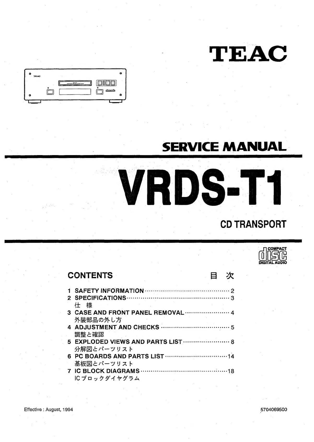
TEAC
oloo
(1
eee
SERVICE
MANUAL
_
VRDS-T1
CD
TRANSPORT
Z
COMPACT
DIGITAL
AUDIO
©
CONTENTS
BR
1
SAFETY
INFORMATION
-:ccceeceeccecccrec
cece
eeeeeeeeeneeeseeeee
D)
2:
SPECIFICATION
Si
kos
tes
ces
cena
incendie
nxss
ncas
tepenaceneaeees
3
{t BR
;
3
CASE
AND
FRONT
PANEL
REMOVAL
--------+--serersee
ee
4
HEE
ORLA
.
4
ADJUSTMENT
AND
CHECKS
«-eeeeeeceeeeeeeceeeeeeeeeess
seers
5
2
HER
5
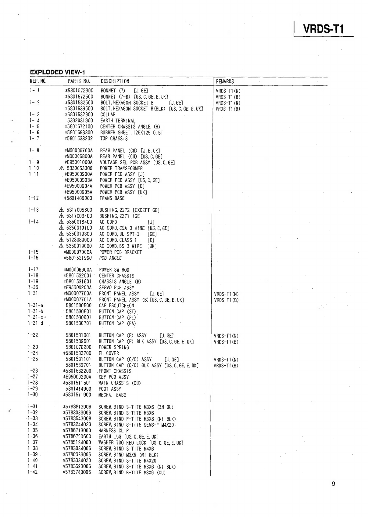
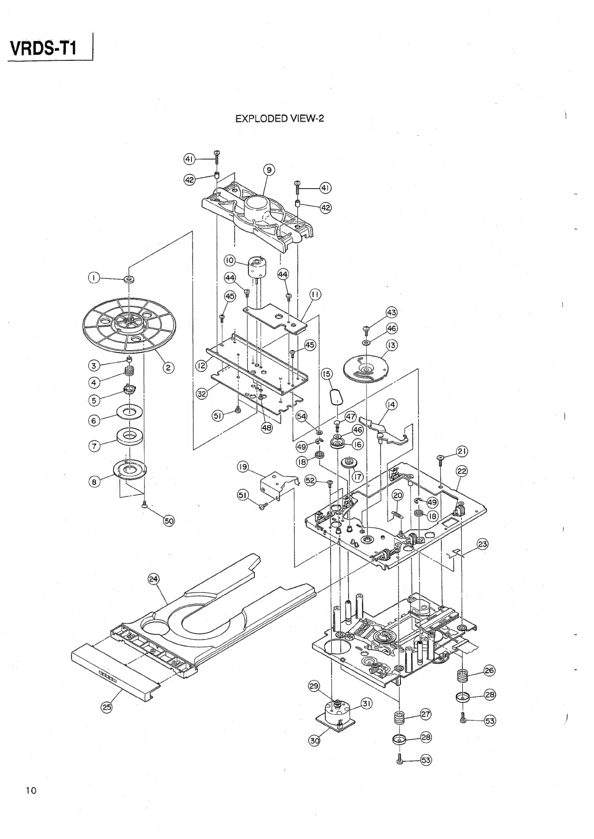
EXPLODED
VIEWS
AND
PARTS
LIST
------------++e
essere
8
SABRIEN-YURAb
.
6
PC
BOARDS
AND
PARTS
LIST
cevcececereecectececeeeeeeeeees
14
BRB
EN-YURAS
7
16
BLOCK
DIAGRAMS
iiss
esesedse
cesses seests
i
esvonausecy
da
seen
18
ICFOyvyISAVIDA
Effective
:
August,
1994
5704069500