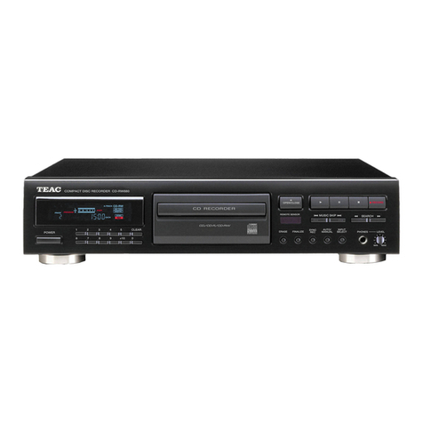
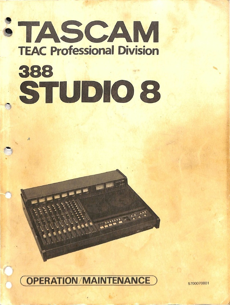
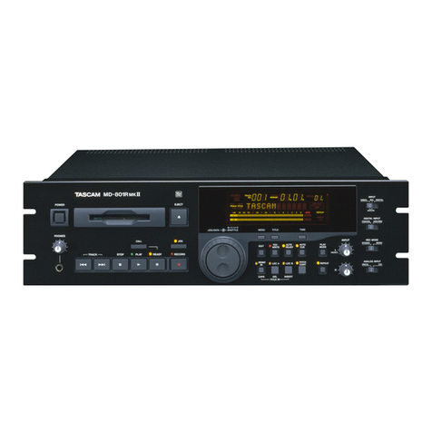
Teac MT-20D-IO User manual

TEAC
MT-2ST/20D-IO
STREAMING
CASSETTE
MAGNETIC
TAPE
UNIT
MAINTENANCE
MANUAL

TEAC
MT-2ST/20D-IO
STREAMING
CASSETTE
MAGNETIC
TAPE
UNIT
~~INTENANCE
MANUAL
TEAC
CORPORATION
fiN:
10
1(;03)4
-0/
REV.
A

CONTENTS
3.
THEORY
OF
OPERATION
3-1
Outline
of
construction
and
functions
••.••.....•..••..••••••••
3-1-1
Overall
block
diagram
......•..•.••.•.•.•..••....••....•••
3-1-2
Outline
of
mechanical
section
.••.....•.•.•.••...•••...•.•
3-2
Operation
of
data
recording/reproducing
system
(PCBA
Drive
Control)
..•••••••••.••••.•.••••.••.•••.•••••••••••
3-2-1
Read
circuit
..........................................•..
3-2-2
Write
circuit
and
erase
circuit
••••••.•••.•••.•••••••••••
3-3
Operaiton
of
tape
drive
systm
(PCBA
Drive
Control)
....••••..•.
3-3-1
Servo
circuit
•...•.••....•..•.•••.•••.•.••..••...••.•...•
3-3-2
Other
control
circuits
••..........•.....•••..•..•..••...•
3-4
"D/CAS"
Interface
control
(PCBA
Interface
Control)
...........
.
3-4-1
CPU
.•.•.•..••••..........•..••••..................•.•.•..
3-4-2
3-4-3
3-4-4
3-4-5
3-4-6
3-4-7
3-4-8
ROM
RAM
Host
interface
control
........•••..•••......••••••.....••
DMAC
Counter/timer
...........................................
.
Write/read
control
..•.•.....••..•.•••....•......•.....••.
I/O
port
.....•••.•..•.••••..•....•••••..•••.••.•..•..••••
301
301
304
311
311
315
317
317
319
321
322
323
323
324
328
329
330
334
3-5
"SCSI"
Interface
control
(PCBA
Interface
Control).............
335
3-5-1
CPU.
. . . . . . . . . . . . . •• • • . . • . . . . . . • . . •• • • • . . . • . • • . . . . . • • . • • • . 336
3-5-2
3-5-3
3-5-4
3-5-5
3-5-6
3-5-7
3-5-8
ROM
RAM
Host
interface
control
......••.•...........•..............
DMA.C
•••••••••••••••••••••••••••••••••••••••••••••••••••••
Counter/timer
..........•............•....•.......•••.•••.
Write/read
control
..••......•...•.•.•..•••.•.••.....••.•.
I/O
port
................••.............••.........••.....
337
337
338
344
345
346
350
3-6
"BASIC"
Interface
control
(PCBA
Interface
Control)............
351
3-6-1
Configuration
.........••.................•.........•.....
351
3-6-2
Theory
of
operation
...•.....•..........................••
354
- i -
3-7
Functions
of
test
points,
variable
resistors
and
straps
..•....
359
3-7-1
Functions
of
test
points
.............•....•.......•......
361
3-7-2
3-7-3
Functions
of
variable
resistors
••.....••....•.........•..
Functions
of
straps
.•.....•.•..•••..••••......•........•.
377
379
4.
MAINTENANCE
4-1
Outline
of
maintenance
...••.•..•....•••........•••••.••.•••.••
4001
4-1-1
Routine
maintenance
..•.•.•.....•••......•••.•....•••.•••.
4001
4-1-2
Check
and
adjustment
.•...••....••......•..••••..••.••••••
4002
4-1-3
Maintenance
parts
....•.•..•.•........••••••.•......•...••
4004
4-1-4
Maintenance
articles
.••...•.•..•.••.....•........•..•.••.
4007
4-2
Precautions
on
maintenance
••..•••..•.•••....•...••...••••...••
4009
4-2-1
4-2-2
4-2-3
4-2-4
4-2-5
4-2-6
4-2-7
Screw
tightening
torque
and
screw
lock
(red)
.•••..••...•.
4009
Connector
handling
method
••••••..••...•.•••••.•.••••.•.•.
4010
How
to
handle
the
protector
guide
•...•••••.••...••.....•.
4015
Cable
treatment
within
chassis
.•••••..•......••.••...•.•.
4017
Initialization
of
SOA
Initialization
of
SOB
Initialization
of
SOD
4019
4021
4023
4-2-8
Initialization
of
SOE
•.....•..••.••..•••••..•.•..•.•..••.
4025
4-3
Check
and
adjustment
procedures
.......•......•.•••••...•...•..
4027
4-3-1
Positional
adjustment
of
reel
motor
(F),
(R)
Ass'y
.....••
4027
4-3-2
4-3-3
4-3-4
4-3-5
4-3-6
4-3-7
4-3-8
4-3-9
4-3-10
4-3-11
4-3-12
4-3-13
4-3-14
Height
adjustment
of
encoder
roller
Check
of
rotary
direction
of
reel
motor
•••••••.......•.••
Check
of
file
protect
sensor
....•••....•••.........•....•
Cassette
loading/unloading
check
•••....••.•........•.....
Check
of
head
shift
....•....•.....••.......••........•..•
Check
and
adjustment
of
tape
winding
.•.•......•..........
Check
and
adjustment
of
head
alignment
.....•.............
Check
of
AGe
operation
•.........•...•...............•....
Check
and
adjustment
of
BOT/EOT
hole
sensor
..•...•....•..
Check
and
adjustment
of
tape
speed
.•.....••.••...•..•..•.
Check
of
start/stop
time
........••.......••......•.•..•..
Check
of
ISV
.....•........•....•••........•..•......•....
Check
and
adjustment
of
read
preamplifier
level
......•...
-
ii
-
4029
4032
4034
4036
4037
4038
4042
4048
4050
4054
4058
4060
4062

4-3-15
4-3-16
4-3-17
4-3-18
4-3-19
4-3-20
Check
and
adjustment
of
read
level
....•...•...•......•...
Check
of
feed
through
.....•..............•••..•.•....••..
Check
of
resolution
...••.•••..••..•...•....••..•••••.•.••
Check
of
earse
level
••......••••••.••.•...••.....•..••.•.
Check
of
peak
shif
t
..•..•..••.••..•..••..••....••••...•.•
Check
of
asymmetry
..•..••......•.•.••..•..•••••....•••••.
4-3-21
Check
and
adjustment
of
VFO
operating
point
•••••••••.••••
4-3-22
Overall
check
.••••••..•....•.•....•••••........••.•..••..
4-4
Replacement
of
maintenance
parts
.••.••.•••••...•..••••...••••.
4-4-1
Replacement
of
head
Ass'y
••....•.•.••••.•...••••.•......•
4-4-2
Replacement
of
reel
motor
(F),
(R)
Ass'y
••.•..••..•..•...
4-4-3
4-4-4
4-4-5
4-4-6
4-4-7
4-4-8
4-4-9
4-4-10
4-4-11
4-4-12
Replacement
of
interrupter
C
Ass'y
Replacement
of
LED
hole
sensor
Ass'y
•••..•••••.•••••...••
Replacement
of
sensor
guide
Ass'y
..•.•••.••••••••••••.••.
Replacement
of
encoder
Ass'y,
encoder
roller
.••.•.•..••••
Replacement
of
solenoid
Ass'y
•.••...••.•.•••••.••....•••.
Replacement
of
head
base
Ass'y
•.••.•••••••••••••••.••••..
Replacement
of
PCBA
Drive
Control
•••...•.•••••.•.••.••.•.
Replacement
of
PCB
A
Interface
Control
••••.....•••..•..•.•
Replacement
of
front
bezel
.••..........••.••.•••..•......
Replacement
of
ej
ect
button
•.....•......••.....•...•..•••
5.
DRAWING
AND
PARTS
LISTS
4064
4066
4067
4069
4070
4071
4072
4074
4078
4078
4083
4087
4090
4093
4095
4100
4105
4111
4112
4113
4115
5-1
Configuration.
••••.•
••
. • • .
.••.•
. .
••.
. . .
•••
•
••••••
.
•••••
• •
••
. • . 501
5-2
Disassembly
drawing
and
parts
lists
of
mechanical
section
.••••
506
5-2-1
Mechanical
parts
of
MTU
...••••...••.•.••.••.••••••...•...
506
5-2-2
Screws
and
washers
5-3
Parts
list
of
PCB
Ass'y
5-3-1
PCBA
Drive
Control
5-3-2
5-3-3
PCBA
Interface
Control
......................
~
......•.....
In
terrupter
C
Ass'
Y
..................•.....•........•..•.
509
510
511
520
526
5-4
Circuit
diagrams
and
parts
location
diagrams
......•.........•.
528
5-4-1
Overall
circuit
diagram
......•.......••...•....•.........
529
5-4-2
PCBA
drive
control.......................................
531
5-4-3
PCBA
interface
control...................................
538
-
iii
-

Fig.
301
Fig.
302
Fig.
303
Fig.
304
Fig.
305
Fig.
306
Fig.
307
Fig.
308
Fig.
309
Fig.
310
Fig.
311
Fig.
312
Fig.
313
Fig.
314
Fig.
315
Fig.
316
Fig.
317
Fig.
318
Fig.
319
Fig.
320
Fig.
321
Fig.
322
Fig.
323
Fig.
324
Fig.
325
Fig.
326
Fig.
327
Fig.
328
Fig.
329
Fig.
330
Fig.
331
Fig.
332
FIGURES
AND
TABLES
Overall
block
diagram
•..•••••••••••••.••••••.•.••••••••.•••
301
Cassette
tape
loading/unloading
mechanism
.•••••.•••••••••••
Cassette
loading.
and
unloading
Cassette
tape
face
identifier
mechanism
••••••••••••••••••••
Read
shif
t
mechanism
......................................
.
Cassette
tape
loading
detection
mechanism
•••••••••.•••••.••
Write
inhibit
hole
detection
mechanism
••••••••••••.••••••••
Marker
detection
mechanism
Read
circuit
block
diagram
306
306
307
309
310
310
310
313
Example
of
operational
waveforms
of
read
circuit
••••••.•.••
314
Write
circuit
and
erase
circuit
block
diagram
••••••••••••••
315
Servo
circuit
block
diagram
••••••••••••••••••••••••••••••••
317
Other
control
circuits
block
diagram
•••••.•••••••••••••••••
319
Interface
bus
timing
•••••••••••.••••.••••••..••••••••••.•••
324
Host
interface
control
circuit
•••••.•••••••••••.•.•••••••••
325
Timing
in
write
operation
••••••••••••••••••.•••••••••••••••
326
Timing
in
read
operation
•••••••.•••••••••••••••••••••••••••
326
Channel
2
timing
in
write
operation
••••••••••••••••••••••••
328
Write/read
control
logic
block
diagram
•.•••••••••.•••••••.•
331
VFO
circuit
block
diagram
•..••••••••.•••.••••••••••••••••••
332
VFO
circuit
timing
.........................................
332
Selection
operation
timing
•••••••••••••••••••.•••••••••••••
338
Command
transfer
timing
•••••••••••••••.••••••••••••••••••••
340
Read
data
transfer
timing
342
Channel
2
timing
in
write
operation
(30
ips)
•••••.••••••.••
344
Write/read
control
logic
block
diagram
•••.••..•••••••••••••
347
VFO
circuit
block
diagram
•••.•..••••••.•.•••••••.•.•.••.••.
348
VFO
circuit
timing
•••...••.••••••••.•••••••.••••.••••••...•
348
Hardware
block
diagram
......•............
..•..........
.....
352
Initial
control
•••••••••.••••••••••••••.••••.••••••••.•..•.
354
Motion
control
••.•••••..••.•••...•••••.•.••••.•••...•.•..•.
355
Tape
position
management
•.•.......•••.••.••••••••...••••.•.
356
-
iv
-

Fig.
333
Fig.
334
Fig.
335
Fig.
336
Fig.
337
Fig.
338
Fig.
339
Fig.
340
Fig.
341
Fig.
342
Fig.
343
Fig.
344
Fig.
345
Fig.
346
Fig.
347
Fig.
348
Fig.
349
Fig.
350
Fig.
351
Fig.
352
Fig.
353
Fig.
354
Fig.
355
Fig.
356
Fig.
357
Fig.
358
RDP
conversion
Cassette
load
delay
•••••..•...•.•.•.•.........•....•.••....
Tach
pulse
conversion
•.•.••.....•.•...•.....•........•.....
Positions
of
test
points,
variable
resistors
and
straps
•.••
Example
of
waveform
at
TP1
....•.....••••..•....•......•••.•
Example
of
waveform
at
TP7
•••..•.•.•••..•..•.•....•...•••••
Example
of
waveform
at
TP8
Example
of
waveform
at
TP11
Example
of
waveform
at
TP13
Example
of
waveform
at
TP14
Example
of
waveform
at
TP1
Example
of
waveform
at
TP2
Example
of
waveform
at
TP3
Example
of
waveform
at
TP4
Example
of
waveform
at
TP5
Example
of
waveform
at
TP6
Example
of
waveform
at
TP9
Example
of
waveform
at
TP1
Example
of
waveform
at
TP2
Example
of
waveform
at
TP3
Exmaple
of
waveform
at
TP4
Example
of
waveform
at
TP5
Example
of
waveform
at
TP6
Example
of
waveform
at
TP1
Example
of
waveform
at
TP2
Example
of
waveform
at
TP3
357
357
358
359
361
362
362
363
364
364
366
367
367
368
368
369
370
371
372
372
373
373
374
375
375
376
Fig.
359 Example
of
waveforms
at
TP4
and
TP5
..•.....•....•..•.•..•..
376
Fig.
401
Connector
types
........•.••................................
4011
Fig.
402
Fig.
403
Fig.
404
Fig.
405
How
to
extract
the
connector
How
to
insert
the
connectors
Sectional
view
of
housing
(black
connector)
...............
.
Terminal
numbers
4012
4012
4013
4013
Fig.
406
Handling
methods
for
connector
J9
..................•.......
4014
- v -

Fig.
407
Fig.
408
Fig.
409
Fig.
410
Fig.
411
Fig.
412
Fig.
413
Fig.
414
Fig.
415
Fig.
416
Fig.
417
Fig.
418
Fig.
419
Fig.
420
Fig.
421
Fig.
422
Fig.
423
Fig.
424
Fig.
425
Fig.
426
Fig.
427
Fig.
428
Fig.
429
Fig.
430
Fig.
431
Fig.
432
Fig.
433
Fig.
434
Fig.
435
Fig.
436
Fig.
437
Fig.
438
Fig.
439
Fig.
440
How
to
detach
the
protector
guide
How
to
attach
the
protector
guide
4016
4016
Cable
treatment
within
chassis
•••...••.•......•.•.........•
4018
Setting
of
SAO
MODE
switch
•.•...••.•••..••.•........•.•....
4019
Connections
of
SOA
Connections
of
SOB
Connections
of
SOD
Connections
of
SOE
4020
4022
4024
4026
Positional
adjustment
of
reel
motor
(F),
(R)
Ass'y
....••••.
4028
Set
ting
of
J l.gs
..••.•.•...•..•••.•.•.••....••••••••..••...•
4030
Height
adjustment
of
encoder
roller
..•......•••••••...••...
4031
Bonding
of
encoder
roller
4031
Check
of
rotary
direction
of
reel
motor
....••••••••.•.•.•..
4033
Mounting
of
FPT
J l.g
•.••.•••.••••.••••..••••••..•••••.•.•••.
4035
Check
of
file
protect
sensor
•.•••.•••..•.••.•......•••..••.
4035
Loading
of
mirror
cassette
•....•...••••••.•.••.••••••..••••
4040
Tape movement
check
(tape
guide)
..•.............•..••......
4041
Tape movement
check
(encoder
roller)
....•..................
4041
Burst
signal
...........•.................••.......•..•..•.•
4043
Adjusting
screws
of
head
alignment
.....................•...
4047
Check
of
AGC
operation
Check
of
AGC
operation
Hole
detection
waveform
at
TP13
Hole
detection
waveform
at
TP13
4048
4049
4051
4053
ISV
measuring
method
..••.••••••..•..•.••...••••.••••.•••.•.
4060
Measurement
of
read
preamplifier
level
.....................
4062
Indication
of
Error
Count
on
SOD
Replacement
of
Head
Ass'y
Replacement
of
Head
Ass'y
Replacement
of
Reel
Motor
Replacement
of
Reel
Motor
Replacement
of
interrupter
Replacement
of
interrupter
Replacement
of
interrupter
(F)
, (R)
(F),
(R)
C
Ass'y
C
ASs'y
C
Ass'y
-
vi
-
Ass'y
(1)
...............
Ass'y
(2)
...............
(1)
·
....................
(2)
·
.....................
(3)
·
....................
4076
4080
4082
4085
4086
4088
4089
4089

Fig.
441
Fig.
442
Fig.
443
Fig.
444
Fig.
445
Fig.
446
Fig.
447
Fig.
448
Fig.
449
Fig.
450
Fig.
451
Fig.
452
Replacement
of
LED
hole
sensor
Ass'y
••••••••••.••••••..•.•.
Replacement
of
sensor
guide
Ass'
y
•..••••.....••.•••..••••••
Replacement
of
encoder
roller
•••..••••••••••.••••••••.•.••.
Replacement
of
encoder
Ass'y
••••••••.•••••••....•••.••.••.•
Setting
of
tilt
adjusting
jig
.............................
.
Tilt
adjustment
Replacement
of
solenoid
Ass'y
(1)
Replacement
of
solenoid
Ass'y
(2)
Positioning
of
head
base
Ass'y
Replacement
of
head
base
Ass'y
(1)
Replacement
of
head
base
Ass'y
(2)
Replacement
of
head
base
Ass'y
(3)
Fig.
453
Replacement
of
front
bezel
Ass'
y
..........................
.
4092
4094
4097
4098
4099
4099
4102
4103
4104
4109
4109
4110
4114
4115 '
Fig.
454
Replacement
of
eject
Button
.••••••••••••••••
'
•••••••••••••••
Fig.
501
Fig.
502
Fig.
503
Fig.
504
External
view
(1)
External
view
(2)
External
view
(3)
External
view
(4)
502
503
504
505
Fig.
505
Disassembly
drawing
of
mechanical
section
.••••••••••••••.•.
508
Fig.
506
Interrupter
C
Ass'y
527
Table
301
Write/read
signal
corresponding
table
••.••••••.•••••••••..
328
Table
302
Write/read
signal
correspoinding
table
•.•.•••••••••••••••.
344
Table
401
Table
402
Table
403
Table
404
Table
405
Table
501
Table
502
Table
503
Routine
maintenance
items
.••••••.••••••••••••••••••.••.•.•
4001
Check and
adjsutment
items
.....••••.•.••••••••••.•••.••••.
4002
Maintenance
parts
list
..•.......••••..•.•••••••..•.•.••..•
4005
Screw
tightening
torque
....................................
4009
Connection
of
reel
motors
••.••••.••.•••••....••.......•...
4084
Main
components
configuration
of
MTU
..••••••••••..•.••....
501
Parts
list
of
MTU
.••..•...•..•••••..•..•••......••.•......
506
List
of
screws
and
washers
....•••...•.••...•••...•..•.....
509
-
vii
-

-
How
to
Display
Model
Classification
-
More
than
one
model
is
available
according
to
specifications
in
the
MT-2ST
Series.
Sections
3
and
4
of
this
maintenance
manual
provide
the
descrip-
tions
in
common
to
all
the
models,
unless
otherwise
specified.
However,
partially
there
are
special
descriptions
whose
application
is
limited
only
to
particular
models
represented
by
the
following
symbols:
"90
ips"
"30
ips"
"Permalloy
head"
"Ferrite
head"
"D/CAS"
"SCSI"
"BASIC"
Applied
only
to
the
models
in
which
the
tape
speed
is
90
ips
(inch
per
second)
during
data
write/read
opera-
tion.
Applied
only
to
the
models
in
which
the
tape
speed
is
30
ips
during
data
write/read
operation.
Applied
only
to
a
model
on
which
the
parmalloy
head
is
mounted.
Applied
only
to
a
model
on
which
a
ferrite
head
is
mounted.
Applied
only
to
the
D/CAS
interface
model.
Applied
only
to
the
SCSI
interface
model.
Applied
only
to
the
BASIC
interface
model.
-
viii
-

Model
Classification
Table
Designation
Part
No. Tape
speed
Head
Interface
MT-2ST/20D-10 19305060-10 90
ips
Permalloy
head
MT-2ST/20D-11 19305060-11 30
ips
.-
D/CAS
MT-2ST/20D-12 19305060-12 90
ips
Ferrite
head
MT-2ST/20S-13 19305060-13
30
ips
MT-2ST/20S-20 19305060-20 90
ips
Permalloy
head
MT-2ST/20S-21 19305060-21
30
ips
SCSI
MT-2ST/20S-22 19305060-22 90
ips
Ferrite
head
MT-2ST/20S-23 19305060-23
30
ips
MT-2ST/20B-30 19305060-30 90
ips
Permalloy
head
MT-2ST/20B-31 19305060-31 30
ips
BASIC
MT-2ST/20B-32 19305060-32
90
ips
Ferrite
head
MT-2ST/20B-33 19305060-33 30
ips
-
ix
-

SECTION
3
THEORY
OF
OPERATION
-
300
-

\.i.l
o
....
\.i.l \.i.l
I I
........
I
....
I
PCBA
INTERFACE
CoNrROL-
- - - - - - - --l
I
r
PCBADRiVE
CoNTRoL-
- - - - -
--1
I
II
I
RD
I
~~rH~
______
~--
____
~I
____
--
__
~
I
I
READ
HEAD
READ
I I
I I
CPU
8bll
I
I
I
INDICAlOR,
fRDN~
I
I
I
I
I
MOTOR.
REV
I
MOTOR
fWD
I
I
I
I
WRITE
a
ERASE
TRO/2
RMDDE
WD
EelK
TR
012
TR
I/~
TR
0
~y
'---------'
DSO
TSI
I I
I I
I I
I I
, I
I
I
I
I
I
I
I
WRITEIREAD
1-+
CONTROL
~_f_t_..l;TS""'-O--+_---_t_-_+-__i
1/0
PORTS
1-+
CONTROL
a
SERVO
GO
fWD
HIS
lOK
I I
I I
I I
I I
I I
I I
L-
________
J---------il------II-~R
fPT
ACK
ClD
COUNTER
TIMER
DMAC
RAM
INTERFACE
CONTROL
I
I
I
I
I
I
I
I
I
I
I
I
I
I
I
I
I
I
I
I
I
I
c:T'
I-'
o
n
?;'
~
9i
:t:
ONl
REQ
RST
I--f--
XfR
8=:
1
ACK
RDY
EXC
12\1
OV
I I
L-----t--t.--
--
--
__
J
L-...
___
....
~
DIA
I •
ov
I
L
___________________
J
POWER
(a)
"D/CAS
II
Fig.
301
Overall
Block
Diagram

VJ
o
N
READ
IIEAD
I
I
I
I
I
INDICATOR.
fRONT
PANEL
WRIT[
HUD
I------------~\
~
f-I
READ
WRITE
E\
ERASE
I
I
TR
0/2
I
I
AMOOE
I
I
WD
I
WEN
I
EEN
ECLK
TA
012 I
TA
Ill.
~~O
~
I
~e,
I
I
I
: :
SOLENOID,
I
!
MOT~~S"'
--
~,~"
:~:~T
~
.-1-..1.
'
1L
-v-
S :
_____
--'
I !lllAD
READ
I I
DSO
I
TSI
T50
CONTROL
I
E\
I
SERVO
I
GO
I
fWD
I
HIS
I
LOK
I
Ll
WRITE
I
: I
ERASE
HEAD
I
I I
I
~
fJ-~'~
~
,~,,~
:
- -
~
ENCOOE!i
I
~
Dp
I
LEO~~OT/EOT
T
- I I
\~
- - - - - - - - -
~
~I
CAS~!!E
LOAD
I
FI . PRnTFC I
MOTOR.
REV
I
MOTOR
fWD
I
I
12'1
OV
I
L-----t--~-----J
POWER
(b)
"SCSI"
Fig.
301
Overall
Block
Diagram
iPCBA
iNTERFAcE
CoNrRoL-
- - - - - - - - -l
I I
I
I
CPU
I
I
--
I
I Bbll I
I I
I
WRITE/READ
r-
I
I
CONTROL
I
I I
I I
r-
DMAC
I
I
~
I
I I
I I
I I
I I
I
----
ROM
I
I I
I I
I
I
1/0
PORTS
r-
£]
I
fPT I
ACK
I
eLD
I
I I
I I
I I
I
or
~
o0
BSY
INTERFACE
110
~
ACK
r-
CONTROL
~
RST
COUNTER
=t:
TIMER
r-
SEL
..
POR
MSG
-+-CIO
REO
I
..
~V
I
L
___________________
J

w
o
w
READ
HEAO
I
I
I
I
I
INDICATOR,
fRON'9
WRITE
~fAO
,~-----------~,
I
I i
SOLENOID,
I
,
~ENCODER
HEAD I
IIII
MOTOR,
FWD
,...
--
~~
SHIFT
I-
I
('O~,
I
LVS
\ I
I
...
~
I I
,
r--,
I
'IIEAD
READ
I
'I'
::
,i
L
WRIT
I
L J ,---
ERASE
~EAD
, -- I I
READ
WRITE
a
ERASE
TR
0/2
RMODE
I -
'I
I
I;,
~
, I I
:~j;
r-lSENSOR
I CONTROL
a
SERVO
, MOTOR-REV
~BOT/EOT
HOLE
SOLENOID'
,
,,-
- - i
ENCODER
I
Lq-
________
C!-Cl~!
LEO
BOTIEOT
I
-T
CASSETTE
LOAD
I
fiLE
PROTECT
MOTOR
REV
I
MOTOR
FWD
I
I
I
I
(c)
"BASIC"
Fig.
301
Overall
Block Diagram
--GO
--L-
REV
-L-TR3
--t-
TR2
-r-
TRI
-r-
TRO
-r-
RST
-050
-r--
RDP
----UTH
-r--
UH
----
SLD
-r--
CIN
-.--USF
-TCH
--t-WDA
: I
THD
HSO
-+-WEN
-r-
EEN
I
,
L
._~~
________________
-J

3-1-2
Outline
of
mechanical
section
The
mechanical
section
of
this
MTU
(Magnetic
Tape
Unit)
consists
of
a
magnetic
head
moving
mechanism,
tape
drive
mechanism,
and
various
detection
mechanism,
mainly
the
transport
Sub
Ass'y
(sub
assembly).
Each
mechanism
is
assembled
so
as
to
keep
the
stable
quality
using
high
precision
parts,
since
compatibility
is
required
between
MTUs.
During
maintenance,
only
the
maintenance
experts
subjected
to
the
specified
maintenance
training
should
access
the
internal
mechanisms.
In
any
case,
never
give
excessive
shocks
to
the
main
unit,
but
handle
it
very
carefully.
(1)
Transport
Sub
Ass'y
The
transport
Sub
Ass'y
is
the
main
frame
to
mount
each
mechanism
or
PCB
with
the
cassette
tape
loading/unloading
mechanism
as
a
center.
It
consists
of
a
loading
base
(C)
Ass'y,
loading
base
(M)
Ass'y,
lever
base
Ass
'y
and
loading
arm
Ass
'y,
etc.
centering
around
the
chassis.
The
loading/unloading
operation
of
the
cassette
tape
is
performed
as
shown
below.
(a)
Loading
operation
When
the
cassette
tape
is
pushed
in
up
to
the
front
bezel,
the
ejector
on
the
loading
base
(C)
Ass'y
is
moved
in
the
direction
of
insertion,
and
the
cassette
tape
is
attracted
automatically
together
with
the
ejector
by
the
rotary
force
of
the
loading
arm.
When
the
stopper
of
the
ejector
is
released,
the
loading
arm
begins
to
push
the
cassette
tape
and
the
loading
base
(C)
Ass'y
at
the
right
angle
to
the
direction
of
insertion.
When
the
loading
base
(C)
ASs'y
reaches
the
predetermined
position,
the
stopper
of
the
cam
lever
roller
is
released,
and
the
reel
motor
within
the
chassis
is
lifted
together
with
the
loading
base
(M)
Ass
'y,
and
then
the
MTU
is
placed
in
the
cassette
loading
status
(Fig.
302,
303).
-
304
-

(b)
Eject
operation
\.fuen
the
ej
ect
button
located
at
the
lower
right
of
the
front
bezel,
the
loading
base
(M)
Ass'y
is
pushed
down,
and
at
the
same
time,
the
stopper
of
the
loading
base
(C)
Ass'y
is
released.
and
the
reverse
action
to
item
(a)
is
performed
continuously,
and
the
cassette
tape
gets
out
up
to
halfway
from
the
front
bezel.
and
then
the
MTU
is
placed
in
the
cassette
unloading
status
(Fig.
302.
303).
(c)
Cassette
tape
face
identifier
mechanism
If
the
cassette
tape
is
inserted
into
MTU
with
the
face
B
of
the
cassette
tape
up,
the
selector
on
the
ejector
is
turned
clockwise.
When
the
cassette
tape
is
pushed
in
further
in
such
status,
the
selector
touches
the
stopper
of
the
chassis.
and
it
is
not
able
to
insert
the
cassette
further
(Fig.
304).
-
305
-

Transport
@
@~
0 G
@
0
+
~--
~_~
___
L
__________
~_~
I I I
1
______
--
______
' I
I
'-~~~~~~-----------_/~--~,
Fig.302
Cassette
tape
loading/unloading
mechanism
Loading
base
(C)
Ass'y
Cam
lever
Loading
arm
Cassette
tape
Eject
button
Reel
motor
Ass'y
"
J \
I
I
I I
,..--,
c=======
(
Cassette
loading
----W.
~~~~----~==~----~=;==~~=U
status)
:::
III
III
t
L.':
(Unloading
status
)------
Fig.303
Cassette
loading,
and
unloading
-306 -
Chassis
Loading
base
(M)
Ass'y

o
Asymmetrical
slot
Stopper
(
Chassis
)
Selector
a
(
With
face
B
inserted
)
Fig.304
Cassette
tape
face
identifier
mechanism
-307 -

(2)
Magnetic
head
shift
mechanism
The
main
components
of
the
magnetic
head
shift
mechanism
are
a
head
base
Ass'
y
and
solenoid
Ass'
y.
A
magnetic
head
is
mounted
on
the
head
base
of
the
head
base
Ass'y.
The
head
base
is
shifted
up
and
down
(two
positions)
by
the
DC
solenoid.
The
head
base
Ass'y
contains
three
kinds
of
adjusting
screws
to
adjust
the
appropriate
head
positions
with
respect
to
the
tape
winding
position
(Fig.
305).
(3)
Tape
drive
mechanism
The
tape
drive
mechanism
consists
of
two
reel
motor
assemblies,
encoder
and
encoder
roller.
The
tape
causes
the
encoder
roller
fixed
to
the
shaft
of
encoder
to
be
rotated
by
friction.
A
feedback
signal
from
the
encoder
is
sent
to
the
reel
motor
to
apply
servo
effect
to
it
so
that
the
tape
speed
is
kept
always
constant.
(4)
Various
detection
mechanisms
(a)
Cassette
loading
detection
mechanism
This
mechanism
consists
of
a
photo
interrupter
and
a
loading
arm
(M)
to
detect
the
loading
condition
of
the
cassette
tape.
When
the
cassette
tape
is
loaded
onto
the
MTU,
the
optical
detection
path
of
the
photo
interrupter
is
interrupted
by
the
tip
of
the
loading
arm
(M).
In
this
status,'
data
can
be
written
or
read
(Fig.
306).
(b)
Write
inhibit
hole
detection
mechanism
This
mechanism
consists
of
a
photo
interrupter
and
file
protector
to
detect
the
wire
inhibit
hole
on
the
cassette
half
rear
face.
When a
cassette
tape
whose
write
inhibit
hole
is
open
is
loaded,
the
optical
detection
path
of
the
photo
interrupter
is
interrupted
by
the
file
protector.
In
this
status,
the
data
write
function
is
deactivated
and
new
write
operation
is
inhibited,
and
then
the
recorded
data
is
protected
(Fig.
307).
-
308
-
This manual suits for next models
1
Table of contents
Other Teac Recording Equipment manuals

Teac
Teac RW-D280 User manual

Teac
Teac GF-350 User manual

Teac
Teac TASCAM 388 STUDIO 8 Troubleshooting guide

Teac
Teac LP-R500 User manual

Teac
Teac CD-RW890 User manual

Teac
Teac CD-RW880 User manual

Teac
Teac HS-4000 Instruction Manual

Teac
Teac Tascam MD-801MKII User manual

Teac
Teac CD-RW890 User manual

Teac
Teac CD-RW890MKII User manual

Teac
Teac HD-R1 User manual

Teac
Teac Multitrack Series User manual

Teac
Teac Tascam Porta-02MKII Ministudio User manual

Teac
Teac BB-1000CD How to use

Teac
Teac LP-R500 User manual

Teac
Teac GF-650 User manual

Teac
Teac GF-650 User manual

Teac
Teac LX Series User manual

Teac
Teac LP-R400 User manual

Teac
Teac TC-FSRSP-G3 User manual