D01371201A
Z
Strain gauge load cell Instructions for Use
TC-FSRSP(T)-G3
Compression Load Cell
Introduction
Thank you for purchasing the TC-FSRSP(T)-G3 load cell.
Please read this document completely before using this
load cell to achieve its best performance and ensure safe
and proper operation.
Included accessories
If anything is missing or damaged, contact the retailer
where you purchased the product.
Test report × 1
Instructions for Use (this document) × 1
Curved load button × 1
Flat load button × 1
oCompany names and product names in this document are the
trademarks or registered trademarks of their respective owners.
IMPORTANT SAFETY INSTRUCTIONS
VWARNING
If something abnormal occurs
In the unlikely event that the product produces smoke, a
strange smell or noise, for example, continuing to use it in
this abnormal state could cause fire or electric shock. After
cutting off the power, confirm that smoke is no longer being
produced. Then, request repair from the retailer where you
purchased the product.
Do not open the cover.
Never remove the cover from this unit. Doing so could
cause electric shock. Request inspection and repair from
the retailer where you purchased the product. Do not
alter this unit. Doing so could cause fire or electric shock.
Do not put foreign objects or water, for example,
into the unit.
Do not place a container that holds water, for example,
on top of this unit. Liquid overflowing or entering the unit
could cause fire or electric shock.
Do not use the unit with any power supply voltage
other than that specified.
Do not use the unit with any power supply voltage other than
that specified. Doing so could cause fire or electric shock.
VCAUTION
Unsuitable installation locations
Do not place the unit in the following types of locations.
Doing so could cause fire or electric shock.
oLocations where it might be exposed to smoke or steam,
such as near a kitchen table or humidifier
oUnstable locations, including unsteady stands and
tilted places
oLocation that are very humid or dusty
oLocations that are exposed to direct sunlight
When not using the unit for a long time
For safety, cut the power supply when not using this unit
for a long time.
Do not operate a damaged unit.
Precautions for use
oThis unit is not built to be water or splash resistant,
and it cannot be used in conditions when the relative
humidity is high. Moreover, use in atmospheres with
corrosive gases should be avoided.
oBe careful to prevent water, oil and other substances
from getting on the unit.
oAvoid use in conditions where condensation could occur.
oConnect cores to the load cell after discharging (elimi-
nating) static electricity from your body.
oIf the surrounding temperature changes suddenly,
the values output by this device could become
unstable, making accurate measurement impossible.
(This could occur, for example, in a location blown by
warm or cold air.)
oConduct load calibrations periodically.
Installation procedures
To use this product, install one of the included load buttons
(two types) or a part that you have prepared in the central
M2 internal thread as shown in the illustration below.
oTighten the included load button by hand to the position
where the screw stops.
oSince it could loosen during use, we recommend coating
the screw part with threadlocker. Doing so, however,
will make removing the load button more difficult.
Curved load button Flat load button
oWhen attaching a part other than one of the included
load buttons, make certain that it does not touch the
cover. (Refer to the dimensional drawings.)
Since the space between the cover and the attachment
area of the loadbearing part is not always uniform, we
recommend using a part that is smaller than the diameter
of the component attachment area.
Furthermore, since the attached part will sink by more
than 30 μm when a load is applied, leave a sufficient
gap between the part and the cover.
oInstall this unit in a place where the structure is level
and can sufficiently bear the load being used.
oScrew holes for attachment are located in four places.
oThe screw hole dimensions are shown in the table below.
Model Screw hole
dimensions
Tightening
torque
TC-FSRSP(T)-G3 M2.6 (3mm depth) 0.65N·m
Installation surface
Do not use the
central indentation
as an installation
surface.
Precautions when placing loads on the
unit
oMake sure the load is perpendicular to the surface to
which this unit is attached.
oWhen using a flat load button, use it so that the load is
equally distributed within a Ø7mm range.
oApply the load so that it is centered on the center of
the unit. If the load is not centered (eccentric load),
twisting, for example, and measurement errors could
occur. This could even result in damage.
F is the correct
load orientation
F1 is an eccentric
inclined load
F2 is an eccentric
load
F1 F2F F1 F2F
Curved load button Flat load button
oBe careful to avoid turning and twisting from lateral
loads. This could cause troubles like those described
in the previous item.
oTake extra care if the part that you have prepared is
cylindrical. Even during installation, do not allow loads
to be applied from the side or at an angle as shown in
the illustration below. Doing so could cause the screw
part to bend and damage internally.
Moreover, when securing the part, tighten with a torque
of no more than 0.18Nm or use a threadlocker and
tighten gently by hand.
FFBad
Bad
Part
oA curved load button is used in load testing during
production as shown in the illustration below, and the
results are used in the TEDS data and the test report.
Since the load point, load direction and other condi-
tions differ when using a flat load button, differences in
performance could occur compared to using a curved
load button.
Curved load button used
4 screws (class 12.9 strength steel) in
the bottom attached it to the jig.
0.65N·m tightening torque
F
oBe careful to avoid applying loads that exceed the
rated capacity. In particular, use caution when there are
vibrations because loads that exceed the rated capacity
could occur due to sympathetic vibrations, for example.
oIf the load receiving area (spherical surface) is
contacted by something that is at a different tem-
perature and the load is increased, the values output
by this device could become unstable, making accu-
rate measurement impossible.
In such a case, wait until the temperature difference
ceases to exist before measuring.
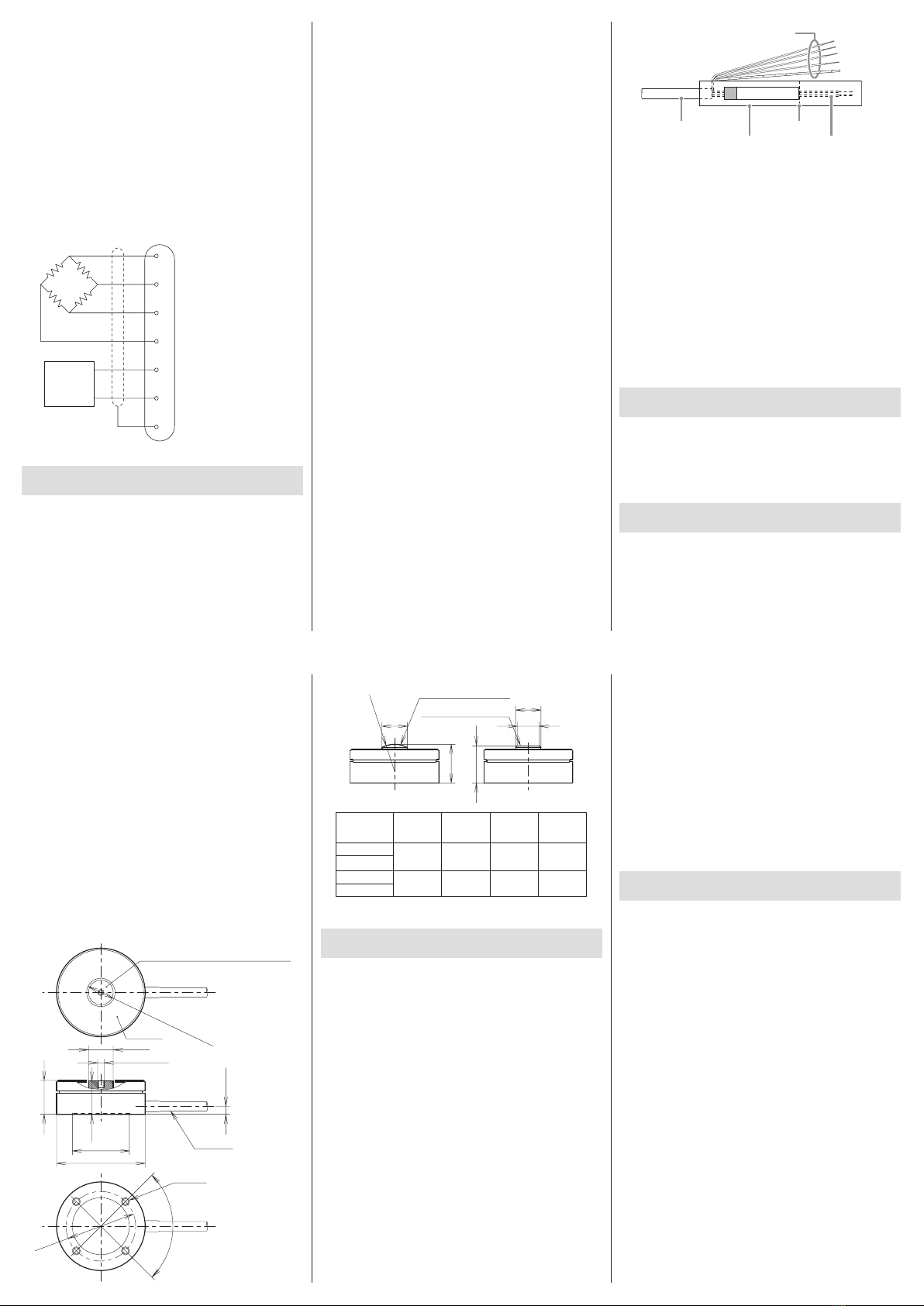
Electrical connection of load cell with
built-in TEDS
oConnect as shown in the illustration below. Incorrect
connections could result in inability to balance and
in errors occurring in the output voltage when loads
are applied.
Using a cable with bare lead wires
Red Input (+)
Black Output (−)
Blue Input (−)
White Output (+)
Orange TEDS signal (+)
Green TEDS signal (COM)
Yellow Shield
TEDS
oThis unit has a built-in TEDS function.
oThe orange and green cores in the cable and the F and
G pins in the connector are wired for TEDS.
oThis unit does not support remote sensing.
oSince products that support remote sensing use the
same cables and connector pins as TEDS, be careful not
to try mistakenly to use these pins for remote sensing.
oSee the operation manuals of indicators and strain
amps that support remote sensing for how to connect
sensors with those units.