Teac CT-W3270 User manual

SERVICE MANUAL
CTW3270
32” WIDE CTV
Effective: DEC01 CTW3270SERV
All manuals and user guides at all-guides.com
all-guides.com

1
CONTENTS
Safety Precautions ........................................................................................................................................... 2
TV Set switched off ........................................................................................................................................... 2
Measurements ................................................................................................................................................. 2
PERI -TV SOCKET ............................................................................................................................................ 2
SC RT 1, SC RT 2 .......................................................................................................................................... 2
INTRODUCTION .............................................................................................................................................. 2
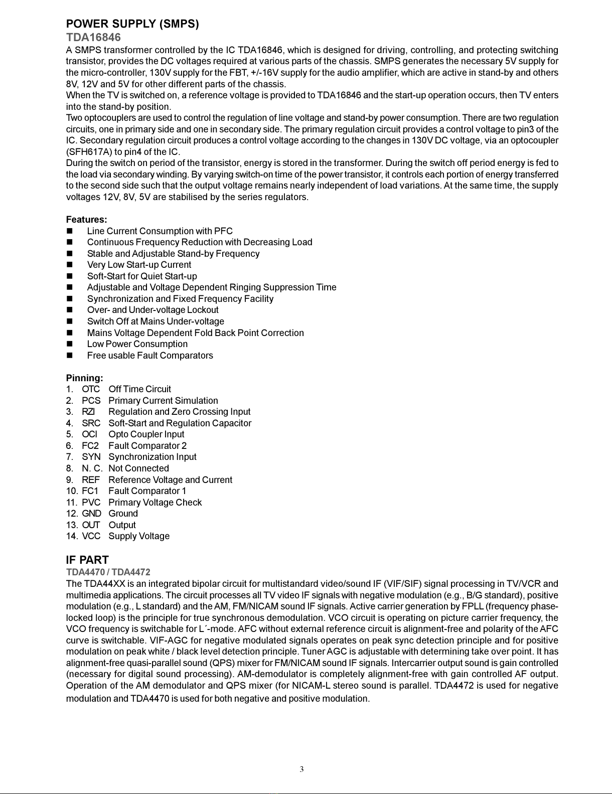
POWER SUPPLY (SMPS) ................................................................................................................................. 3
IF P RT ............................................................................................................................................................. 3-4
TUNER ............................................................................................................................................................. 4-5
S W FILTERS ................................................................................................................................................... 5
DIGIT L TV SOUND PROCESSING ................................................................................................................. 5-6
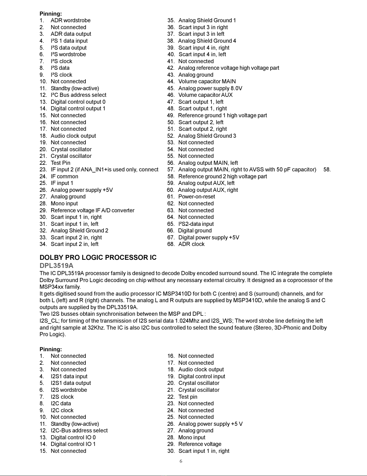
DOLBY PRO LOGIC PROCESSOR ................................................................................................................. 6-7
HE DPHONE OUTPUT .................................................................................................................................... 7
VIDEO OUTPUT ................................................................................................................................................ 7-8
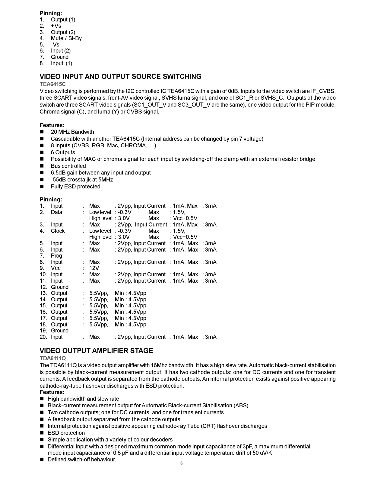
VIDEO INPUT ND OUTPUT SOURCE SWITCHING ...................................................................................... 8
VIDEO OUTPUT MPLIFIER ST GE ................................................................................................................ 8-9
VERTIC L OUTPUT ST GE ............................................................................................................................. 9
MICROTEXT CONTROLLER ............................................................................................................................ 9-10
SERI L CCESS 32K EEPROM ...................................................................................................................... 10-11
DR M ................................................................................................................................................................ 11
EPROM ............................................................................................................................................................. 11
100Hz FE TURE BOX ...................................................................................................................................... 12
VPC32X5 (VIDEO PROCESSOR) ............................................................................................................... 12-13
CIP3250 ...................................................................................................................................................... 13-14
SD 9400 ..................................................................................................................................................... 14-15
DDP3310 .................................................................................................................................................... 15-16
K28 CH SSIS M NU L DJUSTMENTS PROCEDURE ............................................................................... 17
PRELIMIN RY ............................................................................................................................................. 17
SYSTEM VOLT GE JUSTMENT ................................................................................................................ 17
FC DJUSTMENT ..................................................................................................................................... 17
FOCUS DJUSTMENT................................................................................................................................17
SCREEN DJUSTMENT ............................................................................................................................. 17
IF DJUSTMENT FOR LMODE ................................................................................................................... 17
K28 CH SSIS PRODUCTION MODE DJUSTMENTS PROCEDURE ......................................................... 18
PRELIMIN RY ............................................................................................................................................. 18
HORIZONT L ND VERTIC L GEOMETRY LIGNMENTS ........................................................................ 18
V-SHIFT ....................................................................................................................................................... 18
V-SIZE .......................................................................................................................................................... 18
H-SHIFT ...................................................................................................................................................... 18
H-SIZE ......................................................................................................................................................... 18
S-COR ......................................................................................................................................................... 18
LINRT .......................................................................................................................................................... 18
NGLE ........................................................................................................................................................ 18
BOW ... ........................................................................................................................................................ 18
TRPEZ ......................................................................................................................................................... 18
P R B ......................................................................................................................................................... 18
U.COR ......................................................................................................................................................... 19
L.COR ......................................................................................................................................................... 19
VIDEO LIGNMENTS ........................................................................................................................................ 19
RGn, GGn, BGn,:WHITE B L NCE DJUSTMENT .................................................................................... 19
RRf, GRf, BRf .............................................................................................................................................. 19
YDF . ........................................................................................................................................................... 19
GC . .......................................................................................................................................................... 19
TL N . .......................................................................................................................................................... 19
PS . ........................................................................................................................................................... 19
T_T ............................................................................................................................................................ 19
T_P ............................................................................................................................................................ 19
EXT3 ............................................................................................................................................................ 19
CLT ............................................................................................................................................................ 19
SERVICE LIGNMENTS ................................................................................................................................... 20
IMPORT NT ................................................................................................................................................ 20
DJUSTMENTS GROUOP.......................................................................................................................... 20
OPTIONS GROUP ...................................................................................................................................... 20
SYSTEM GROUP ........................................................................................................................................ 20
GENER L BLOCK DI GR M OF CH SSIS K28 ........................................................................................... 21
All manuals and user guides at all-guides.com

2
DO NOT CHANGE ANY MODULE UNLESS THE SET IS SWITCH OFF
The mains supply side of the switch mode power supply transformer is live.
Use an isolating transformer.
The receivers fulfill completely the safety requirements.
Safety precautions
Servicing of this TV should only be carried out by a qualified person.
- Components marked with the warning symbol on the circuit diagram are critical for safety and must only be replaced
with an identical component.
- ower resistor and fusable resistors must be mounted in an identical manner to the original component.
- When servicing this TV, check that the EHT does not exceed 26kV.
TV Set switched off
Make short-circuit between HV-CRT clip and CRT ground layer.
Short C804 (150mF) before changing IC802 or other components in primary side of SM S.
Measurements
Voltage readings and oscilloscope traces are measured under following conditions.
Antenna signal 60dB from colourbar generator. (100% white, 75% colour saturation)
Brightness, contrast, colour set for a normal picture.
Mains supply, 220VAC, 50Hz.
PERI-TV SOCKET
SCART 1 (SC050) SCART 2 (SC051)
1 Audio right output 0.5Vrms / 1K 1 Audio right output 0.5Vrms / 1K
2 Audio right input 0.5Vrms / 10K 2 Audio right input 0.5Vrms / 10K
3 Audio left output 0.5Vrms / 1K 3 Audio left output 0.5Vrms / 1K
4 Ground AF 4 Ground AF
5 Ground Blue 5 Ground Blue
6 Audio left input 0.5Vrms / 10K 6 Audio left input 0.5Vrms / 10K
7 Blue input 0.7Vpp / 75ohm 7 Blue input 0.7Vpp / 75ohm
8 AV switching input 0-12VDC /10K 8 AV switching input 0-12VDC /10K
9 Ground Green 9 Ground Green
10 - 10 -
11 Green input 0.7Vpp / 75ohm 11 -
12 - 12 -
13 Ground Red 13 Ground Red
14 Ground Blanking 14 Ground Blanking
15 Red input 0.7Vpp / 75ohm 15 -
16 Blanking input 0-0.4VDC, 1-3VDC / 75ohm 16 -
17 Ground CVS output 17 Ground CVS output
18 Ground CVS input 18 Ground CVS input
19 CVS output 1Vpp / 75ohm 19 CVS output 1Vpp / 75ohm
20 CVS input 1Vpp / 75ohm 20 CVS input 1Vpp / 75ohm
21 Ground 21 Ground
INTRODUCTION
11Ak28 is a 100Hz flicker free colour television capable of driving 284:3/16:9, 334:3 and 294:3 real flat picture tubes.
The chassis is capable of operation in AL, SECAM, NTSC (playback) colour standards and multiple transmission standards
as B/G, D/K, I/I, and L/L´.Sound system output is supplying 12W (10%THD) for left, right and center outputs of 8ohm speakers,
and 2 x 7W for surround outputs of 2 x 4ohm speakers, connected in series.
TV supports the hightext (level 2.5) teletext standard. It is possible to decode transmissions including high graphical data.
The chassis is equipped with one full EuroScart, two other SCARTs for AV input/output, one front-AV input, one back-AV output,
one headphone output, one SVHS input (via SCART and SVHS connector), one VGA input, two external speaker outputs (left
and right), one centre speaker output, and one surround speaker output for two speakers in series.
All manuals and user guides at all-guides.com

3
POWER SUPPLY (SMPS)
TDA16846
A SM S transformer controlled by the IC TDA16846, which is designed for driving, controlling, and protecting switching
transistor, provides the DC voltages required at various parts of the chassis. SM S generates the necessary 5V supply for
the micro-controller, 130V supply for the FBT, +/-16V supply for the audio amplifier, which are active in stand-by and others
8V, 12V and 5V for other different parts of the chassis.
When the TV is switched on, a reference voltage is provided to TDA16846 and the start-up operation occurs, then TV enters
into the stand-by position.
Two optocouplers are used to control the regulation of line voltage and stand-by power consumption. There are two regulation
circuits, one in primary side and one in secondary side. The primary regulation circuit provides a control voltage to pin3 of the
IC. Secondary regulation circuit produces a control voltage according to the changes in 130V DC voltage, via an optocoupler
(SFH617A) to pin4 of the IC.
During the switch on period of the transistor, energy is stored in the transformer. During the switch off period energy is fed to
the load via secondary winding. By varying switch-on time of the power transistor, it controls each portion of energy transferred
to the second side such that the output voltage remains nearly independent of load variations. At the same time, the supply
voltages 12V, 8V, 5V are stabilised by the series regulators.
Features
nLine Current Consumption with FC
nContinuous Frequency Reduction with Decreasing Load
nStable and Adjustable Stand-by Frequency
nVery Low Start-up Current
nSoft-Start for Quiet Start-up
nAdjustable and Voltage Dependent Ringing Suppression Time
nSynchronization and Fixed Frequency Facility
nOver- and Under-voltage Lockout
nSwitch Off at Mains Under-voltage
nMains Voltage Dependent Fold Back oint Correction
nLow ower Consumption
nFree usable Fault Comparators
Pinning
1. OTC Off Time Circuit
2. CS rimary Current Simulation
3. RZI Regulation and Zero Crossing Input
4. SRC Soft-Start and Regulation Capacitor
5. OCI Opto Coupler Input
6. FC2 Fault Comparator 2
7. SYN Synchronization Input
8. N. C. Not Connected
9. REF Reference Voltage and Current
10. FC1 Fault Comparator 1
11. VC rimary Voltage Check
12. GND Ground
13. OUT Output
14. VCC Supply Voltage
IF PART
TDA4470 / TDA4472
The TDA44XX is an integrated bipolar circuit for multistandard video/sound IF (VIF/SIF) signal processing in TV/VCR and
multimedia applications. The circuit processes all TV video IF signals with negative modulation (e.g., B/G standard), positive
modulation (e.g., L standard) and the AM, FM/NICAM sound IF signals. Active carrier generation by F LL (frequency phase-
locked loop) is the principle for true synchronous demodulation. VCO circuit is operating on picture carrier frequency, the
VCO frequency is switchable for L´-mode. AFC without external reference circuit is alignment-free and polarity of the AFC
curve is switchable. VIF-AGC for negative modulated signals operates on peak sync detection principle and for positive
modulation on peak white / black level detection principle. Tuner AGC is adjustable with determining take over point. It has
alignment-free quasi-parallel sound (Q S) mixer for FM/NICAM sound IF signals. Intercarrier output sound is gain controlled
(necessary for digital sound processing). AM-demodulator is completely alignment-free with gain controlled AF output.
Operation of the AM demodulator and Q S mixer (for NICAM-L stereo sound is parallel. TDA4472 is used for negative
modulation and TDA4470 is used for both negative and positive modulation.
All manuals and user guides at all-guides.com

4
Features
n5V supply voltage; low power consumption
nActive carrier generation by F LL principle (frequency-phase-locked-loop) for true synchronous demodulation
nVery linear video demodulation, good pulse response and excellent intermodulation figures
nVCO circuit is operating on picture carrier frequency, the VCO frequency is switchable for the L mode
nAlignment-free AFC without external reference circuit, polarity of the AFC curve is switchable
nVIF-AGC for negative modulated signals (peak sync detection) and for positive modulation (peak white/black level detector).
nTuner AGC with adjustable take over point
nAlignment-free quasi parallel sound (Q S) mixer for FM/NICAM sound IF signals
nIntercarrier output signal is gain controlled (necessary for digital sound processing)
nComplete alignment-free AM demodulator with gain controlled AF output
nSeparate SIF-AGC with average detection
nTwo independent SIF inputs
narallel operation of the AM demodulator and Q S mixer (for NICAM-L stereo sound)
nackage and relevant pinning is compatible with the single standard version TDA 4472;simplifies the design of an
universal IF module
Pinning
1. Input sensitivity, RMS value : 80mVrms
2. Input sensitivity, RMS value : 80mVrms
3. SIF Input selector switch : 2.0 V
4. Ground
5. IF gain control range : 65dB
6. Input sensitivity, RMS value : 80mVrms
7. Input sensitivity, RMS value : 80mVrms
8. IF gain control range : 65dB
9. Ground
10. Available tuner-AGC current : 2mA
11. Available tuner-AGC current : Min : 0.3V Max : 13.5V
12. Video output : Min : 1.8V Max : 2.2V
13. Standard switch : Min : 0V Max : 0.8V
14. L switch : Min : 0V Max : 3.0V
15. IF gain control range : 65dB
16. Ground
17. Internal reference voltage
18. F LL and VCO : Min : 1mA Max : 4mA
19. AFC switch : Min : 0V Max : 0.8V
20. F LL and VCO : Min : 1mA Max : 4mA
21. F LL and VCO : Min : 1mA Max : 4mA
22. AFC output : 0.7 mA/kHz
23. DC supplay : Min : 4.5V Max : 9.0V
24. DC output voltage : 2V
25. AF output-AM : 2.2V
26. F LL and VCO : Min : 1mA Max : 4mA
27. Input sensitivity, RMS value : 80mVrms
28. Input sensitivity, RMS value : 80mVrms
TUNER
The hardware and software of the TV is suitable for tuners, supplied by different companies, which are selected from the
Service Menu. These tuners can be combined VHF, UHF tuners suitable for CCIR systems B/G, H, L, L´, I/I´, and D/K. The
tuning is available through the digitally controlled I2C bus ( LL). Below you will find info on one of the Tuners in use.
General description of UV1316
The UV1316 tuner belongs to the UV 1300 family of tuners, which are designed to meet a wide range of applications. It is a
combined VHF, UHF tuner suitable for CCIR systems B/G, H, L, L, I and I. The low IF output impedance has been designed
for direct drive of a wide variety of SAW filters with sufficient suppression of triple transient.
Features of UV1316
nMember of the UV1300 family small sized UHF/VHF tuners
nSystems CCIR: B/G, H, L, L, I and I; OIRT: D/K
nDigitally controlled ( LL) tuning via I2C-bus
nOff-air channels, S-cable channels and Hyperband
nWorld standardised mechanical dimensions and world standard pinning
nCompact size
nComplies to CENELEC EN55020 and EN55013
All manuals and user guides at all-guides.com

5
Pinning
1. Gain control voltage (AGC) : 4.0V, Max:4.5V
2. Tuning voltage
3. I²C-bus address select : Max:5.5V
4. I²C-bus serial clock : Min:-0.3V, Max:5.5V
5. I²C-bus serial data : Min:-0.3V, Max:5.5V
6. Not connected
7. LL supply voltage : 5.0V, Min:4.75V, Max:5.5V
8. ADC input
9. Tuner supply voltage : 33V, Min:30V, Max:35V
10. Symmetrical IF output 1
11. Symmetrical IF output 2
SAW FILTERS
K9453 Two channels switchable sound IF saw filter of BG, DK, I, L systems for input channel 2 and of L´
system for input channel 1.
K3953 Two channel switchable video IF saw filter of BG, DK, I, L systems for input channel 2 and of L´
system for input channel 1.
J3950 Video IF saw filter for I system
DIGITAL TV SOUND PROCESSING
MSP3410D
The MS 3410D is an I2C controlled single-chip multistandard sound processor for applications in analog and digital TV
sets. The full TV sound processing, starting with analog sound IF signal-in, down to processed analog AF-out is
performed in a single-chip covering all European TV-standards. It is designed to simultaneously perform digital
demodulation and decoding of NICAM-coded TV stereo sound, as well as demodulation of FM-mono TV sound and two
FM systems according to the German or Korean terrestrial specs. It is also possible to do AM-demodulation according to
the SECAM system. There is AGC for analog inputs: 0.14 - 3Vpp. All demodulation and filtering is performed on chip and
is individually programmable. All digital NICAM standards (B/G, L, and I) are realised. Only one crystal clock (18.432Mhz)
is necessary. External capacitors at each crystal pin to ground are required. They are necessary for tuning the open-loop
frequency of the internal LL and for stabilising the frequency in closed-loop operation. The higher the capacitors, the
lower the clock frequency result. The nominal free running frequency should match the centre of the tolerance range
between 18.433 and 18.431Mhz as closely as possible. By means of standardised I2S interface, additional feature
processors (D L35xx, Dolby rologic processor for this chassis) can be connected to the IC.
I2S bus interface consists of five pins:
I2S_DA_IN12 for input four channels (two channels per line) per sampling cycle (32Khz).
I2DA_OUT, for output, two channels per sampling cycle (32KHz).
I2S_CL, for timing of the transmission of I2S serial data, 1.024Mhz.
I2S_WS, for the word strobe line defining the left and right sample.
Features:
n5-band graphic equalizer (as in MS 3400C)
nEnhanced spatial affect (pseudo stereo / base-width enlargement as in MS 3400C)
nHeadphone channel with balance, bass treble, loudness
nBalance for loudspeaker and headphone channels in dB units (optional)
nAdditional pair of D/A converters for SCART2 out
nImproved over-sampling filters (as in MS 3400C)
nAdditional SCART input
nFull SCART in/out matrix without restrictions
nSCART volume in dB units (optional)
nAdditional I²S input (as in MS 3400C)
nNew FM-identification (as in MS 3400C)
nDemodulator short programming
nAuto-detection for terrestrial TV-sound standards
nrecise bit-error rate indication
nAutomatic switch from NICAM to FM/AM or vice versa
nImproved NICAM synchronisation algorithm
nImproved carrier mute algorithm
nImproved AM-demodulation
nADR together with DR 3510A
nDolby ro Logic together with D L 35xx A
nReduction of necessary controlling
nLess external components
nSignificant reduction of radiation
All manuals and user guides at all-guides.com
all-guides.com

6
Pinning
1. ADR wordstrobe 35. Analog Shield Ground 1
2. Not connected 36. Scart input 3 in right
3. ADR data output 37. Scart input 3 in left
4. I²S 1 data input 38. Analog Shield Ground 4
5. I²S data output 39. Scart input 4 in, right
6. I²S wordstrobe 40. Scart input 4 in, left
7. I²S clock 41. Not connected
8. I²S data 42. Analog reference voltage high voltage part
9. I²S clock 43. Analog ground
10. Not connected 44. Volume capacitor MAIN
11. Standby (low-active) 45. Analog power supply 8.0V
12. I²C Bus address select 46. Volume capacitor AUX
13. Digital control output 0 47. Scart output 1, left
14. Digital control output 1 48. Scart output 1, right
15. Not connected 49. Reference ground 1 high voltage part
16. Not connected 50. Scart output 2, left
17. Not connected 51. Scart output 2, right
18. Audio clock output 52. Analog Shield Ground 3
19. Not connected 53. Not connected
20. Crystal oscillator 54. Not connected
21. Crystal oscillator 55. Not connected
22. Test in 56. Analog output MAIN, left
23. IF input 2 (if ANA_IN1+is used only, connect 57. Analog output MAIN, right to AVSS with 50 pF capacitor) 58.
24. IF common 58. Reference ground 2 high voltage part
25. IF input 1 59. Analog output AUX, left
26. Analog power supply +5V 60. Analog output AUX, right
27. Analog ground 61. ower-on-reset
28. Mono input 62. Not connected
29. Reference voltage IF A/D converter 63. Not connected
30. Scart input 1 in, right 64. Not connected
31. Scart input 1 in, left 65. I²S2-data input
32. Analog Shield Ground 2 66. Digital ground
33. Scart input 2 in, right 67. Digital power supply +5V
34. Scart input 2 in, left 68. ADR clock
DOLBY PRO LOGIC PROCESSOR IC
DPL3519A
The IC D L3519A processor family is designed to decode Dolby encoded surround sound. The IC integrate the complete
Dolby Surround ro Logic decoding on chip without any necessary external circuitry. It designed as a coprocessor of the
MS 34xx family.
It gets digitised sound from the audio processor IC MS 3410D for both C (centre) and S (surround) channels, and for
both L (left) and R (right) channels. The analog L and R outputs are supplied by MS 3410D, while the analog S and C
outputs are supplied by the D L33519A.
Two I2S busses obtain synchronisation between the MS and D L :
I2S_CL; for timing of the transmission of I2S serial data 1.024Mhz and I2S_WS; The word strobe line defining the left
and right sample at 32Khz. The IC is also I2C bus controlled to select the sound feature (Stereo, 3D- honic and Dolby
ro Logic).
Pinning
1. Not connected 16. Not connected
2. Not connected 17. Not connected
3. Not connected 18. Audio clock output
4. I2S1 data input 19. Digital control input
5. I2S1 data output 20. Crystal oscillator
6. I2S wordstrobe 21. Crystal oscillator
7. I2S clock 22. Test pin
8. I2C data 23. Not connected
9. I2C clock 24. Not connected
10. Not connected 25. Not connected
11. Standby (low-active) 26. Analog power supply +5 V
12. I2C-Bus address select 27. Analog ground
13. Digital control IO 0 28. Mono input
14. Digital control IO 1 29. Reference voltage
15. Not connected 30. Scart input 1 in, right
All manuals and user guides at all-guides.com

7
31. Scart input 1 in, left 50. Scart output 2, left
32. Analog Shield Ground 1 51. Scart output 2, right
33. Scart input 2 in, right 52. Analog Shield Ground 3
34. Scart input 2 in, left 53. Not connected
35. Analog Shield Ground 2 54. Not connected
36. Scart input 3 in, right 55. Not connected
37. Scart input 3 in, left 56. Analog output Channel 1, left
38. Analog Shield Ground 4 57. Analog output Channel 1, right
39. Not connected 58. Reference ground 2 high voltage part
40. Not connected 59. Analog output Channel 2, left
41. Not connected 60. Analog output Channel 2, right
42. Analog reference voltage high voltage part 61. ower-on-reset
43. Analog ground 62. Not connected
44. Volume capacitor Channel1 63. Not connected
45. Analog power supply 8.0 V 64. I2S2-data output
46. Volume capacitor Channel 2 65. I2S2-data input
47. Scart output 1, left 66. Digital ground
48. Scart output 1, right 67. Digital power supply +5 V
49. Reference ground 1 high voltage part 68. Not connected
EADP ONE OUTPUT
TDA1308
The TDA1308 is an integrated class AB stereo headphone driver. It gets its input from two analog audio outputs (DACA_L
and DACA_R) of MS 3410D. The gain of the output is adjustable by the feedback resistor between the inputs and outputs.
Features
nWide temperature range
nNo switch ON/OFF clicks
nExcellent power supply ripple rejection
nLow power consumption
nShort-circuit resistant
nHigh performance - high signal-to-noise ratio
- high slew rate
- low distortion
nLarge output voltage swing
Pinning
1. Output A (Voltage swing) : Min : 0.75V, Max : 4.25V
2. Inverting input A : Vo(clip) : Min : 1400mVrms
3. Non-inverting input A : 2.5V
4. Ground
5. Non-inverting input B : 2.5V
6. Inverting input B : Vo(clip) : Min : 1400mVrms
7. Output B (Voltage swing) : Min : 0.75V, Max : 4.25V
8. ositive supply : 5V, Min : 3.0V, Max : 7.0V
AUDIO OUTPUT
TDA7265
The TDA7265 is a 25W+25W stereo sound amplifier with mute/stand-by facility. ST A control signal coming from microcontroller
(when it is at high level) activates the mute function. IC is muted when mute port is at low level. Two stereo audio signals
coming from audio module is injected to the inputs of the IC and a power of 12Wrms (10%) is obtained. An external pop-
noise circuitry pulls AF inputs of the IC in order to eliminate pop noise when TV is turned on or off via mains supply
connection. It is possible to adjust the gain of the amplifiers by feedback external resistors.
Features
nWide supply voltage range (up to 50V ABS Max.)
nSplit supply
nHigh output power: 25+25 W @ TDA = 10%, RL = 8ohm, VS = ±20V
nNo pop at turn-on / off
nMute (pop free)
nStand-By feature (low IQ)
nFew external components
nThermal overload protection
nAdjustable gain via an external resistor
All manuals and user guides at all-guides.com

8
Pinning
1. Output (1)
2. +Vs
3. Output (2)
4. Mute / St-By
5. -Vs
6. Input (2)
7. Ground
8. Input (1)
VIDEO INPUT AND OUTPUT SOURCE SWITC ING
TEA6415C
Video switching is performed by the I2C controlled IC TEA6415C with a gain of 0dB. Inputs to the video switch are IF_CVBS,
three SCART video signals, front-AV video signal, SVHS luma signal, and one of SC1_R or SVHS_C. Outputs of the video
switch are three SCART video signals (SC1_OUT_V and SC3_OUT_V are the same), one video output for the I module,
Chroma signal (C), and luma (Y) or CVBS signal.
Features
n20 MHz Bandwith
nCascadable with another TEA6415C (Internal address can be changed by pin 7 voltage)
n8 inputs (CVBS, RGB, Mac, CHROMA, )
n6 Outputs
nossibility of MAC or chroma signal for each input by switching-off the clamp with an external resistor bridge
nBus controlled
n6.5dB gain between any input and output
n-55dB crosstaljk at 5MHz
nFully ESD protected
Pinning
1. Input : Max : 2Vpp, Input Current : 1mA, Max : 3mA
2. Data : Low level : -0.3V Max : 1.5V,
High level : 3.0V Max : Vcc+0.5V
3. Input : Max : 2Vpp, Input Current : 1mA, Max : 3mA
4. Clock : Low level : -0.3V Max : 1.5V,
High level : 3.0V Max : Vcc+0.5V
5. Input : Max : 2Vpp, Input Current : 1mA, Max : 3mA
6. Input : Max : 2Vpp, Input Current : 1mA, Max : 3mA
7. rog
8. Input : Max : 2Vpp, Input Current : 1mA, Max : 3mA
9. Vcc : 12V
10. Input : Max : 2Vpp, Input Current : 1mA, Max : 3mA
11. Input : Max : 2Vpp, Input Current : 1mA, Max : 3mA
12. Ground
13. Output : 5.5Vpp, Min : 4.5Vpp
14. Output : 5.5Vpp, Min : 4.5Vpp
15. Output : 5.5Vpp, Min : 4.5Vpp
16. Output : 5.5Vpp, Min : 4.5Vpp
17. Output : 5.5Vpp, Min : 4.5Vpp
18. Output : 5.5Vpp, Min : 4.5Vpp
19. Ground
20. Input : Max : 2Vpp, Input Current : 1mA, Max : 3mA
VIDEO OUTPUT AMPLIFIER STAGE
TDA6111Q
The TDA6111Q is a video output amplifier with 16Mhz bandwidth. It has a high slew rate. Automatic black-current stabilisation
is possible by black-current measurement output. It has two cathode outputs: one for DC currents and one for transient
currents. A feedback output is separated from the cathode outputs. An internal protection exists against positive appearing
cathode-ray-tube flashover discharges with ESD protection.
Features
nHigh bandwidth and slew rate
nBlack-current measurement output for Automatic Black-current Stabilisation (ABS)
nTwo cathode outputs; one for DC currents, and one for transient currents
nA feedback output separated from the cathode outputs
nInternal protection against positive appearing cathode-ray Tube (CRT) flashover discharges
nESD protection
nSimple application with a variety of colour decoders
nDifferential input with a designed maximum common mode input capacitance of 3pF, a maximum differential
mode input capacitance of 0.5 pF and a differential input voltage temperature drift of 50 uV/K
nDefined switch-off behaviour.
All manuals and user guides at all-guides.com

9
Pinning
1. Non-inverting voltage input
2. Supply voltage LOW
3. Inverting voltage input
4. Ground, substrate
5. Black current measurement output
6. Supply voltage HIGH
7. Cathode transient voltage output
8. Cathode CD voltage output
9. Feedback voltage output
VERTICAL OUTPUT STAGE
TDA9379FA
The IC TDA9379FA is the vertical deflection booster circuit. Two supply voltages, +12V and 12V are needed to scan the
inputs VERT+ and VERT-, respectively. And a third supply voltage, +45V for the flyback limiting are needed. The vertical
deflection coil is connected in series between the output and feedback to the input.
Features
n ower Amplifier
n Thermal rotection
n Output Current up to 2.6App
n Flyback Voltage up to 90V
n External Flyback Supply
Pinning
1. Inverting Input
2. Supply Voltage
3. Flyback Supply
4. GND or Negative Supply
5. Output
6. Output Stage Supply
7. Non-inverting Input
MICROTEXT CONTROLLER
SDA30C264
The SDA30C264 is the microcontroller used with the Megatext IC. Its architecture and instruction set are based upon
that of the 8051 microcomputer. Like the 8051 it has many features which increase programming ease; extended internal
data memory-space, variable manipulation in internal data memory, free stack location in data RAM, 4 register banks,
special function registers, memory mapped I/O, individually addressable bits, and a Boolean processor which gives the
programmer the ability to improve the power of the software development. The IC produces the following input or output
control signals; AGC_CON, MODE_SW, L / L, I _MODS, I _SEL, ON/OFF (stand-by), SC1..3_IN_AV (pin 8
information from 3 SCARTs), AFC, MUTE (to mute audio output IC), I2CEN.
The SDA30C26x family, a derivative of the SAB C501, is a member of family of single-chip computers, in which the
emphasis is no longer placed on purely numeric computational performance, but on application-specific controller
functions.
Architecture and instruction set are based upon that of the 8051 microcomputer. Like the 8051 has many features which
increase programming ease; extended internal data memory-space, variable manipulation in internal data memory, free
stack location in data RAM, 4 register banks, special function registers, memory mapped I/O, individually addressable
bits and a Boolean processor give the programmer the ability to improve the power of software development. Numerical
problems can be processed with binary as well as with BCD-arithmetic. The many bit handling instructions also
contribute to the computers efficiency as a controller, Extended memory is controlled by an 8-bit data and a (16+3)-bit
address bus without any additional devices such as latches or logic elements, even when all 512K of the program
address space is used. All this leads, in suitable applications, to a reduction in the peripheral hardware and to a
simplification of the software and thus to reduced development and component costs. The controller, specially developed
for entertainment electronic applications, can also be recommended where both lowest component costs and a large
production volume are prime requirements.
The SDA 30C36x family members contain a 1024 + 256-byte or a 2048 + 256-byte data memory (XRAM + RAM), two
independent 16-bit timers /-counters and a seven-source, four-priority-level, nested interrupt structure, on-chip oscillator
and clock circuits. The 30 digital I/O-lines include four 8-bit ports ( 1 and 3 contain I/O-lines with multifunction options)
and one 2-bit port. One or two serial interfaces are included, one behaves like the 8051 UART, the other is a I²C Bus
interface (SDA 30C264 only)
The second multifunction port consists of port 1, which alternatively can be used as up to eight independent pulse width
modulated output channels ( WM). Controlled via special function registers, the WM-circuitry provides flexibility in time
resolution and system configuration.
Specially the realisation of D/A-outputs using pulse width modulation will be a cost saving advantage in analog
applications.
All manuals and user guides at all-guides.com

10
The internal ADC is an 8-bit, four-channel converter. The input channels are 20 to 23, the analog supply are pins VDDA
and VSSA. A flexible overvoltage / undervoltage detector is included (SDA 30C264 only).
ort 4 can be used as a standard port or as memory extension address bits.
Increased system reliability can be achieved by activating the integrated watchdog timer.
Efficient use of program memory results from an instruction set consisting of 49 single-byte, 46 two-byte and 16 three-
byte instructions. Using an internal clock frequency of 12 MHz, 64 instructions execute in 0.5 us and 45b instructions
execute in 1.0us. The remaining instructions (multiple and devide) require only 2us. The number of bytes in each
instruction and the number of oscillator periods required for execution are listed in the instruction
Based on the SDA 30C163 and similar to the SDA 30C164, the SDA 30C26x comprise double stack size for the
extension memory (32 byte) and seven additional data pointer registers.
The SDA 30C263 is a reduced version of the SDA 30C264. The SDA 30C264 is functionally compatible to the
SDA 30C164, but uses a different package and a different Reset input stage ( -MQF -80-1 instead of -LCC-84).
If using the -MQF -64-1 ackage, some I/O-features are not available.
Features
nSAB 8051 Architecture
- On-chip oscillator and clock circuits
- Binary or decimal arithmetic
- Signal-overflow detection and parity computation
- Integrated Boolean processor for control applications
- Full depth stacks for subroutines return linkage and data storage
- Four priority level, nested interrupt structure
- 0.5us instruction cycle at 12 MHz internal clock rate
- 8 data pointer registers
nSerial interface
- Full duplex UART-interface
- I²C compatible interface (SDA 30C264 only)
nOn-Chip RAM
- Direct byte and bit addressability
- Four register banks
- 256 bytes of data memory, including 128 user-defined software flags
- 2048 bytes of data memory accessible with MOVX-instructions (SDA 30C263; 1024 bytes)
nExternal Program Memory Interface
- 512 Kbytes of program memory may be addressed by a 8-bit data bus and a 16 + 3-bit address bus
- Extension stacks depth 32 byte
n30 Bi-directional I/O-Lines
- Two 8-bit ports, one comprising up to eight programmable D/A-outputs
- One 4-bit input port, also used for analog input
- One 8-bit port with open drain output
- One 2-bit port with optional memory extension function
nPulse Width Modulation Unit
- Up to eight programmable WM-output channels for low cost digital-to-analog conversion
nTimers
- Two 16-bit general purpose timer/event counters
- Watchdog timer
nAnalog-to-Digital Converter
- Four multiplexed input channels with 8-bit resolution
- Overvoltage/Undervoltage Detector with interrupts capability
SERIAL ACCESS 32K EEPROM
24LC32A
It is the 32Kbit electrically erasable programmable memory. The memory is compatible with the I2C standard, two wire serial
interface, which uses a bi-directional data bus and serial clock.
Features
nSingle supply with operation down to 2.5V
- Maximum writes current 3mA at 6.0V
- Standby current 1mA max at 2.5V
n2-wire serial interface bus, I 2 CÔ compatible
n100 kHz (2.5V) and 400 kHz (5V) compatibility
nSelf-timed ERASE and WRITE cycles
nower on/off data protection circuitry
nHardware write protect
n1,000,000 Erase/Write cycles guaranteed
n32-byte page or byte writes modes available
nSchmitt trigger filtered inputs for noise suppression
All manuals and user guides at all-guides.com
all-guides.com

11
nOutput slope control to eliminate ground bounce
n2 ms typical write cycle time, byte or page
nUp to eight devices may be connected to the same bus for up to 256K bits total memory
nElectrostatic discharge protection > 4000V
nData retention > 200 years
n8-pin DI and SOIC packages
nTemperature ranges
- Commercial (C): 0°C to +75°C
- Industrial (I): -40°C to +85°C
Pinning
1. A0 User Configurable Chip Select
2. A1 User Configurable Chip Select
3. A2 User Configurable Chip Select
4. Vss Ground
5. SDA Serial Address/Data I/O
6. SCL Serial Clock
7. W Write rotect Input
8. Vcc +2.5V to 6.0V ower Supply
DRAM
HYB514400BJ
The HYB514400BJ is the new generation dynamic RAM organised as 1M by 4-bit. It utilises CMOS silicon gate process as
well as advances circuit techniques to provide wide operation margins both internally and for the system user. This DRAM is
used with Megatext IC to store teletext pages.
Features
n1 048 576 words by 4-bit organisation
n0 to 70 °C operating temperature
nFast age Mode Operation
nSingle +5V (± 10 %) supply with a built-in VBB generator
nLow power dissipation
max. 660mW active (-50 version)
max. 605mW active (-60 version)
max. 550mW active (-70 version)
nStandby power dissipation
11mW max. Standby (TTL)
5.5mW max. Standby (CMOS)
1.1mW max. Standby (CMOS) for low ower Version
nOutput unlatched at cycle and allows two-dimensional chip selection
nRead, writes, read-modify write, CAS-before-RAS refreshes,RAS-only refresh hidden refresh and test mode capability
nAll inputs and outputs TTL-compatible
n1024 refresh cycles / 16 ms
n1024 refresh cycles / 128 ms Low ower Version only
nlastic ackages: -SOJ-26/20-5 with 300mil width
EPROM
ST27C2001
The ST27C2001 is 2097 152-bit, ultra-violet erasable, electrically programmable read-only memory. This device is fabricated
using power-saving CMOS technology for high speed and simple interface with MOS and bipolar circuits. All inputs (including
program data inputs) can be driven by series 74TTL circuits without the use of external pull-up resistors. Each output can
drive one series 74 TTL circuit without external resistors. Software for user interface and control of hardware circuitry are
stored in this IC.
Features
nOrganisation ...256K x 8
nSingle 5-Vpover supply
nOperationally Compatible with Existing Megabit E ROMs
nIndustry Standard 32-pinDual-in-line ackage
nAll inputs/Outputs Fully TTL Compatible
nMax Access/Min Cycle Time
n8-Bit Output for Use in Microprocessor-Based Systems
nower Saving CMOS Technology
n3-State Output Buffers
n400 mV Minimum DC Noise Immunity with Standard TTL Loads
nLatchup Immunity of 250mA on all input and output pins
nNo pull-up resistors required
nLow power dissipation (Vcc = 5.5V)
- Active 165mW Worst case
- Standby 0.55mW Worst case (CMOS-Input levels)
All manuals and user guides at all-guides.com

12
100 z FEATURE BOX
VPC3215, CIP3250, SDA9400, DDP3310
The feature box consists of four I2C controlled ICs:
Video rocessor V C3215
Component Interface rocessor CI 3250
Digital Image rocessor SDA9400
Digital Deflection rocessor DD 3310
The input supplies to the feature box are +12V, +5V. The ICs do also need a supply of 3.3V, which is regulated
by IC4 LM314.
Besides the composite video in normal operation and luma/chroma inputs in the SVHS applications, there are also R-G-
B-FB inputs from the I module.
OSD R-G-B-FB inputs from the Megatext IC or from the controller in the case of TV-text option. While the 50Hz sync
signals for I are supplied by the V C3215, the 100Hz sync signals for OSD are supplied by the DD 3310.
Control signals for HV stage such as VertQ, Vert, HDrive, EW (East-West) and SVM (Scan Velocity Modulation) are
produced by this module. V rot and H rot input signals are used for protection. There are also a flyback sample signal
from HV stage and the sense signal from the CRT board.
The feature box also supports the VGA mode.
VPC32X5 (Video Processor)
Figure 1
As seen in figure 1 all the processings in V C are digital. This IC has four composite, one SVHS input, and one composite
output which is used for teletext. In AK28 the main video input is Vin2, which is also used for luma input in SVHS applications.
After switching the inputs the signals are converted to digital via two 8 bit ADCs. And these digital data are processed to
produce the 4:2:2 formatted digital YUV signals. The main features are, multi-standard color decoding including all sub-
standards, multi-standard sync processing, adaptive 4H comb filter, linear horizontal scaling, as well as nonlinear horizontal
scaling (panorama vision.) It provides 50Hz vertical and 15625Hz horizontal sync signals for the I module.
Features
n all-digital video processing
n high-performance adaptive 4H comb filter Y/C separator with adjustable vertical peaking
n multi-standard color decoder AL/NTSC/SECAM including all substandards
n 4 composite, 1 S-VHS input, 1 composite output
n integrated high-quality A/D converters and associated clamp and AGC circuits
n multi-standard sync processing
n linear horizontal scaling (0.25 ... 4), as well as non-linear horizontal scaling panorama vision
n AL+ preprocessing (V C 3215)
n line-locked clock, data and sync output (V C 3215)
n display/deflection control (V C 3205)
n submicron CMOS technology
n I2C-Bus Interface
n one 20.25 MHz crystal, few external components
n 68-pin LCC package
All manuals and user guides at all-guides.com

13
Pinning
1 Ground 35. Ground
2 Ground 36. Supply Voltage
3 5 MHz Clock Out 3847. icture Bus Chroma
4 Standby Supply Volt 4850. icture Bus riority
5 Analog Crystal Out 51. Ground
6 Analog Crystal In 52. VGAV Input
7 Ground 53. Front-End/ Back-End Data
9 Ground 54. Reset Input, Active Low
10 Interlace Out 55. I2C Bus Data
12 Vertical Sync ulse 56. I2C Bus Clock
13 Front Sync ulse 57. Test in, connect to GND
14 Main Sync/Horiz Sync ulse 58. Video 4 Analog Input
15 Helper Line Output 59. Ground
16. Horz Clamp ulse 60. Video 3 Analog Input
17. Active Video Out 61. Video 2 Analog Input
18. Double Output Clock 62. Video 1 Analog Input
19. Output Clock 63. Chroma/ Video 4 Analog Input
20...29. icture Bus Luma 64. Analog Video Output
26. Ground 65. Analog Shield GND F
27. Not Connected 66. Supply Voltage, Analog Front-End
30. Main Clock Output 20.25 MHz 67. Signal Ground for Analog Input
31. Supply Volt 68. Reference Voltage Top, Analog
34. Ground
CIP3250:
The IC is used to interface the analog input, which is output from the I module (SCART RGB or I RGB). As can be seen
from the block diagram, there is a CT-BR-SAT block, which is used for luma contrast, brightness, hue, and color saturation
correction. The soft mixer is controlled by the fast blank signal.
Features
n analog input for RGB or YUV and Fast Blank
n triple 8 bit analog to digital converters for RGB/YUV with internal programmable clamping
n single 6 bit analog to digital converter for Fast Blank signal
n digital matrix RGB % YUV (Y, BY, RY)
n luma contrast and brightness correction for signals from analog input
n color saturation and hue correction for signals from analog input
n digital input for DIGIT 2000 or DIGIT 3000 formats
n digital interpolation to 4:4:4 format
n high quality soft mixer controlled by Fast Blank signal
n programmable delays to match digital YUVin and ana-log RGB/YUV
n variable low pass filters for YUV output
n digital output in DIGIT 2000 and DIGIT 3000 formats, as well as RGB 4:4:4
n I2C bus interface
n clock frequency 13.5... 20.25 MHz
All manuals and user guides at all-guides.com

14
Pinning
1. Standby connect to ground 54. Main Clock Input
29. Blue Output 55. Reset Input
1017. Green/Luma Output 56. In Test Mode connect to ground
18. ad Ground 57. Analog Supply Voltage +5 V
19. ad Supply Voltage +5 V/+3.3 V 58. Analog Ground
2027. Red/Chroma Output 59. Reference External Capacitor
28. Active Video Output 60. Substrate connect to ground
29. Active Video Input 61. Fast Blank Input
30. Front Sync Input 62. Ground Fast Blank
31. I2C Clock Input/Output 63. Blue/U Input
32. I2C Data Input/Output 64. Ground Blue/U
3335. icture Bus riority 65. Green/Luma Input
3643. Chroma Input 66. Ground Green/Luma
4451. Luma Input 67. Red/V Input
52. Digital Ground 68. Ground Red/V
53. Digital Supply Voltage +5 V
SDA9400:
SDA9400 converts the scan rate from 50/60 Hz to 100/120 Hz
Features
Two input data formats
-4:2:2 luminance and chrominance parallel (2 x 8 wires)
-ITU-R 656 data format (8 wires)
Two different representations of input chrominance data
-2s complement code
- ositive dual code
Flexible input sync controller
Flexible compression of the input signal
-Digital vertical compression of the input signal (1.0, 1.25, 1.5, 1.75, 2.0, 3.0, 4.0)
-Digital horizontal compression of the input signal (1.0, 2.0, 4.0)
Noise reduction
-Motion adaptive spatial and temporal noise reduction (3D-NR)
-Temporal noise reduction for luminance frame based or field based
-Temporal noise reduction for chrominance field based
-Separate motion detectors for luminance and chrominance
-Flexible programming of the temporal noise reduction parameters
-Automatic measurement of the noise level (5 bit value, readable by I²C bus)
All manuals and user guides at all-guides.com

15
3-D motion detection
-High performance motion detector for scan rate conversion
-Global motion detection flag (readable by I²C bus)
-Movie mode and phase detector (readable by I²C bus)
TV mode detection by counting line numbers (PAL, NTSC, readable by I²C bus)
Embedded memory
-5 Mbit embedded DRAM core for field memories
-192 kbit embedded DRAM core for line memories
Flexible clock and synchronization concept
-Decoupling of the input and output clock system possible
Scan rate conversion
-Motion adaptive 100/120 Hz interlaced scan conversion
-Motion adaptive 50/60 Hz progressive scan conversion
-Simple static interlaced and progressive conversion modes for 100/120 Hz interlaced
or 50/60 Hz progressive scan conversion : e.g. ABAB, AABB, AA*B*B, AAAA, BBBB, AB, AA*
-Simple progressive scan conversion with joint lines:
50 Hz -> 60, 70, 75 Hz progressive
60 Hz -> 70, 75 Hz progressive
-Large area and line flicker reduction
Flexible digital vertical expansion of the output signal (1.0, ... [1/32] ... , 2.0)
Flexible output sync controller
-Flexible positioning of the output signal
-Flexible programming of the output sync raster
-External synchronization by backend IC possible
(e.g. split screen for one TV channel with joint lines and one C VGA channel)
Signal manipulations
-Insertion of coloured background
-Vertical and/or horizontal windowing with four different speed factors
-Flash generation (for supervising applications, motion flag readable by I²C bus)
-Still frame or field
-Support of split screen applications
-Multiple picture display - Tuner scan (4 and 16 times for 4:3, 12 times for 16:9 tubes)
-Support of multi picture display with I or front-end processor with integrated scaler
(e.g. 9 times display of I pictures, picture tracking, random pictures, still-in-moving picture, moving-in-still picture)
I²C-bus control (400 kHz)
3.3 V ± 5% supply voltage
inning:
2,8,24,42,55 Supply volt ( VSS=0V ) 54. System clock 1
9,25,41,56 Supply volt ( VDD=3.3V ) 17,..,10Data output UV
36,52,58 Supply volt ( VSS=0V ) 7,..,3;1;64;63 Data output Y
35,51,53,57,59 Supply volt ( VDD=3.3V ) 62 Horz active video out
43,..,50 Data input Y 61 V-Sync out / Ext V-Sync
31,..,34;37,..,40 Data input UV 60 H-Sync out / Ext H-Sync
30 System reset. 18 Interlace signal vert deflection
23 H-Sync input 28 Crystal conn / System clock 2
22 V-Sync input 27 Crystal connection
29 Sync enable input 26 Clock output
21 I2C-Bus data line 19 Test input
20 I2C-Bus clock line
DDP3310:
All manuals and user guides at all-guides.com
all-guides.com

16
It is the display and deflection processor. All the horizontal and vertical stages are driven by this IC.
The last controls such as contrast, brightness and saturation of the actual video signal, OSD and VGA are accomplished
by the blocks in DD . Tube measurement and SVM controls are also managed by this IC.
Features
Video processing
linear horizontal scaling (0.25 4)
non-linear horizontal scaling panoramavision
dynamic peaking
soft limiter (gamma correction)
color transient improvement
programmable RGB matrix
picture frame generator
two analog RGB/Fast-Blank inputs
Deflection processing
scan velocity modulation output
high-performance H/V deflection
EHT compensation for vertical / East/West
soft start/stop of H-Drive
vertical angle and bow
differential vertical output
vertical zoom via deflection
horizontal and vertical protection circuit
adjustable horizontal frequency for VGA/SVGA dis-play
Miscellaneous
selectable 4:1:1/ 4:2:2 YC r C b input
selectable 27/ 32-MHz line-locked clock input
crystal oscillator for horizontal protection
automatic picture tube adjustment (cutoff, white-drive)
single 5-V power supply
hardware for simple 50/60-Hz to 100/ 120-Hz con-version (display frequency doubling)
two I2C-controlled WM outputs
beam current limiter
Pinning
1. Supply Voltage 28. Sup Volt, Analog Back-end
2. Gnd, Output in Driver 29. VRD/BCS DAC Ref, Beam Current Safety
3. Additional VSYNC input 30. Fast-Blank1 Input
4. Read counter Reset 31. Analog Red1 Input
5. FIFO Read Enable 32. Analog Green1 Input
6. FIFO Write Enable 33. Analog Blue1 Input
7. FIFO Write counter Reset 34. Fast-Blank2 Input
8. Horz. Drive Output 35. Analog Red2 Input
9. Horz. Flyback Input 36. Analog Green2 Input
10. Safety Input 37. Analog Blue2 Input
11. Vertical rotection Input 38. Test in
12. Select of H-Drv Freq. Range 39. Reset Input, active low
13. Clock Sel 40.5 or 27/32MHz 40. WM out
14. Clock select 27/32 MHz 41. WM out
15. Range Switch2, Measure ADC 42. Half-Contrast
16. Range Switch1, Measure ADC 4350. icture Bus Chroma
17. Sense ADC Input 51. Supply Volt, Digital Circuitry
18. Ground, MADC Input 52. Ground, Digital Circuitry
19. Differential Vert Sawtooth Out 53. Sys. Clock Input(27/32/40.5MHz)
20. Differential Vert Sawtooth Out 5461. Y0 icture Bus Luma
21. E/W Output 62. Single LLC Input(13.5/16MHz)
22. Reference Input for RGB DACs 63. Horizontal Sync Input
23. Scan Velocity Modulation 64. Vertical Sync Input
24. Analog Output Red 65. Analog Crystal Out (5-MHz Security Clock)
25. Analog Output Green 66. Analog Crystal In (5-MHz Security Clock)
26. Analog Output Blue 67. I2C-Bus Data
27. Ground, Analog Back-end 68. I2C-Bus Clock
All manuals and user guides at all-guides.com

17
AK28 CHASSIS MANUAL ADJUSTMENTS PROCEDURE
A) PRELIMINARY
Before starting with the alignment procedure, make sure that all the potentiometers on the chassis and also screen and
focus pots are in the medium position.
B) SYSTEM VOLTAGE ADJUSTMENT
Inputs - AC power (220V 50 Hz).
- AL B/G test pattern via RF
( AL I test pattern for AL I TVs, SECAM D/K pattern, SECAM L/L´/K´ TVs).
Outputs - Digital voltmeter to anode of D110.
Display - System voltage
Action - Apply power. Check that The stand-by led lights.
- Select TV mode and tune to the applied test pattern via local test keyboard.
Chassis should start normally.
- Adjust all analogue controls (volume, bass, treble, brightness, contrast, colour) to minimum settings.
- Adjust VR127 according to the following different types of CRTs
SYSTEM VOLTAGE TYPE OF CRT
135V±0.5V HILI S A66EAK552X54
135V±0.5V HILI S A66EAK071X54
135V±0.5V VIDEOCOLOR A66ECY13X12
135V±0.5V HILI S W66ESF002X44
C) AFC ADJUSTMENT
Inputs - AC power.
- 38.9 MHz test pattern for AL B/G, AL-SECAM B/G or 39.5 MHz test pattern for AL I model
(90dBmV) to Z403 SAW filter input terminals 1 and 2.
Outputs - Digital Voltmeter to AFC point (pin22 of IC401)
Display - AFC Voltage.
Action - Adjust VL401 for 2.5±0.1 Volts. TV should automatically tune to a station when
search tuning is activated.
D) FOCUS ADJUSTMENT
Inputs - AC power
- AL B/G test pattern via RF input.
Outputs - icture tube drive.
Display - icture
Action - Select TV mode and tune to the signal.
- Adjust focus potentiometer (the upper pot on the rear side of the FBT transformer) for optimum
focusing.drive.
E) SCREEN ADJUSTMENT
Inputs - AC power
- AL B/G Colour Bar test pattern via RF
Outputs - 1/100 Oscilloscope probe to RGB cathodes on CRT baseboard.
NOTE Ground pin of probe will be connected to 1st pin (GND) of the CRT socket.
Display - RGB ratio
Action - Select AL B/G Colour Bar pattern using the local test keyboard and the user remote control unit.
- Adjust all control functions (brightness, colour and contrast) to minimum settings.
- Measure the most sensitive cathode
- Adjust the screen potentiometer (lower pot on the rear side of FBT transformer) until cathode voltage
becomes 150V.
F) IF ADJUSTMENT FOR L MODE
Inputs - AC power.
- 38.9 MHz test pattern for AL B/G, AL-SECAM B/G or 39.5 MHz test pattern for AL I model.
(90dBmV) to Z403 SAW filter input terminals 1 and 2.
Outputs - Digital Voltmeter to AFC point. (pin22 of IC401)
- Digital Voltmeter to AFC_L point. (pin14 of IC401)
Display - AFC Voltage.
Action - Firstly adjust VL401 for 2.5 ± 0.1 Volts. TV should automatically tune to a station.
when search tuning is activated.
- Adjust VR401 for 2.5±0.1 Volts at the AFC_L point.
All manuals and user guides at all-guides.com

18
AK28 CHASSIS PRODUCTION MODE ADJUSTMENTS PROCEDURE
A) PRELIMINARY
All system, geometry and white balance alignments are performed in production service mode. Before starting the
production mode alignments, make sure that all manual alignments are done correctly. To start production mode
alignments enter the MAIN MENU and enter the code 1675 by pressing digit keys. roduction mode items will appear
on the screen. roduction mode groups will be displayed with different colours of headlines , so in order to access a
production alignment group press the colour key of the related group on the remote control transmitter. After selecting
one of the production service mode groups, you can access its items by pressing the cursor-up and/or cursor-down
keys. You can change the value of an item by pressing cursor-left and/or cursor-right keys on the remote control
transmitter.
In order to switch between other group of items press the colour key of this groups headline.
To store the settings press OK key. In order to leave this menu press MENU key.
B) HORIZONTAL AND VERTICAL GEOMETRY ALIGNMENTS
- Switch the program to crosshatch test pattern.
- ress RED key to access this group of item.
- Select the items by pressing cursor-up and/or cursor-down keys.
- Adjust the item by pressing cursor-left and/or cursor-right after selecting that item.
- Store the settings by pressing OK key.
- Switch to another item group by pressing the colour keys of the related coloured headline of that group.
- Exit production mode by pressing the MENU key on the remote transmitter..
1) V-SHIFT
- ress cursor-left and/or cursor-right buttons till the test pattern is vertically centred, i.e. horizontal line at the centre of
the test pattern is in equal distance both to upper and lower side of the picture tube. Check and readjust V-SHIFT item if
the adjustment becomes improper after some other geometric adjustments are done
2) V-SIZE
- ress cursor-left and/or cursor-right buttons till horizontal black lines on both the upper and lower part of the test
pattern become very close to the upper and lower horizontal sides of picture tube and nearly about to disappear. Check
and readjust V-SIZE item if the adjustment becomes improper after some other geometric adjustments are done.
3) H-SHIFT
- Adjust H-SHIFT item by pressing cursor-left and/or cursor-right buttons till test pattern is horizontally in equal distance
both to right and left sides of the picture tube. Check and readjust H-SHIFT item if the adjustment becomes improper
after some other geometric adjustments are done.
4) H-SIZE
- Adjust H-WIDTH item by pressing cursor-left and/or cursor-right buttons till no under-scan condition will happen, i.e. no
white bars on the left and right side of the test pattern will be visible nor the picture will be so wide. Check and readjust H-
WIDTH item if the adjustment becomes improper after some other geometric adjustments are done.
5) S-COR
- ress cursor-left and/or cursor-right buttons till the size of squares on both the upper and lower part of test pattern
become equal to the squares laying on the vertical centre of the test pattern. Check and readjust S-COR item if the
adjustment becomes improper after some other geometric adjustments are done.
6) LINRT
- ress cursor-left and/or cursor-right buttons till all the size of squares of the test pattern become in equal size from the
top of the screen to its bottom of the whole screen. Check and readjust LINRT item if the adjustment becomes improper
after some other geometric adjustments (especially after than S-COR adjustment are done.
7) ANGLE
- ress cursor-left and/or cursor-right buttons till the vertical lines of the crosshatch pattern become completely
perpendicular to horizontal lines without any angle of vertical deviation. Check and readjust ANGLE item if the adjustment
becomes improper after some other geometric adjustments are done.
8) BOW
- ress cursor-left and/or cursor-right buttons till the vertical lines especially ones close to the left and right sides will of
equal and symmetrical bending, i.e. they together will neither be towards left side nor right side. Check and readjust
BOW item if the adjustment becomes improper after some other geometric adjustments are done.
9) TRPEZ
- ress cursor-left and/or cursor-right buttons till vertical lines, especially lines at the sides of the picture frame became
parallel to the both sides of picture tube as close as possible. Check and readjust TR EZ item if the adjustment
becomes improper after some other geometric adjustments are done.
10) PARAB
- ress cursor-left and/or cursor-right buttons till vertical lines close to the both sides of the picture frame become parallel
to vertical sides of picture tube without any bending to left or to right side of the screen.. Check and readjust ARAB
item if the adjustment becomes improper after some other geometric adjustments are done.
All manuals and user guides at all-guides.com

19
11) U. COR
- ress cursor-left and/or cursor-right buttons till vertical lines at the upper corners of the picture frame become vertical
and parallel to vertical corner sides of picture tube. Check and readjust U. COR item if the adjustment becomes
improper after some other geometric adjustments are done.
12) L. COR
- ress cursor-left and/or cursor-right buttons till vertical lines at the lower corners of the picture frame become vertical
and parallel to vertical corner sides of picture tube. Check and readjust L. COR item if the adjustment becomes
improper after some other geometric adjustments are done.
C) VIDEO ALIGNMENTS
- Switch the program to crosshatch test pattern for geometric adjustments.
- Switch the program to colour bar test pattern for video adjustments.
- ress GREEN key to access this group of item.
- Select the items by pressing cursor-up and/or cursor-down keys.
- Adjust the item by pressing cursor-left and/or cursor-right after selecting that item.
- Store the settings by pressing OK key.
- Switch to another item group by pressing the colour keys of the related coloured headline of that group.
- Exit production mode by pressing the MENU key on the remote transmitter..
1) RGn, GGn, BGn WHITE BALANCE ADJUSTMENT
- Apply WHITE test pattern via RF.
Adjust all analogue functions to medium level and set GGn, RGn, BGn at value 80, if needed.
Use Colour analyser and monitor the colour temperature (X, Y) on colour analyser.
Select RGn and BGn by cursor-up and/or cursor-down buttons and change the values by cursor-left and/or cursor-
right buttons till the following values are read:
X=285±10
Y=293±10 on the colour analyser.
2) RRf, GRf, BRf
Set the values of these items as 62 (constant).
3) YDF
Apply COLOUR BAR test pattern.
Select YDF item cursor-up and/or cursor-down buttons.
Adjust YDF by pressing cursor-left and/or cursor-right buttons till the colour transients on the colour bar pattern
becomes as sharper and possible as colours between transients do not mix with each other. Check and readjust YDF
item if the adjustment becomes improper after YDV adjustment is done.
4) AGC
Apply AL BG signal, VHF-3 Channel-12 and 60dBmV RF signal level.
Adjust AGC item till voltage at the AGC point (pin1 of the tuner) becomes 3.0 volts.
5) TLAN
This item and its settings will be defined later.
6) APS
This value of this item toggles between ON and OFF while pressing the cursor-left and cursor-right after this item is
selected by cursor-up and/or cursor-down buttons.
In order to activate A S installation procedure whenever TV is turned select ON for the very first time.
In order to start TV without A S installation procedure select OFF.
7) T_T
This item is used for the Tuner Selection.
SAM, THO, SIE, AL , MK2 and MK3 are for Samsung, Thomson, Siemens, Alps and hilips M 2/M 3, respectively.
8) T_P
This item is used for the Tuner Selection.
SAM, THO, TEM, and MK2 are for Samsung, Thomson, Temic, and hilips, respectively.
9) EXT3
This item is toggles between ON and OFF and is used to enable and disable EXT3, respectively.
10) CLT
This item is used to set the Menu colors. 5 choices are possible.
All manuals and user guides at all-guides.com
Other manuals for CT-W3270
1
Table of contents
Other Teac TV manuals

Teac
Teac CT-M3497 User manual

Teac
Teac CT-M5128TXT User manual

Teac
Teac CT-M511S User manual

Teac
Teac LE40UBFHD User manual

Teac
Teac EU-34HT User manual

Teac
Teac CT-M5129STC User manual

Teac
Teac CT-W2850S1 User manual

Teac
Teac CT-F6870S User manual

Teac
Teac DLEDV3989FHDR User manual

Teac
Teac EU2845ST User manual