Teagle Tomahawk 1010 User manual


Ref. Description
1Grease Nipple – Rear
Bed Chain Roller Bush
2Grease Nipples x 2 – At
ends of SC Chute Ram
3Oil Chains –
Crossbeater drive
4Grease Nipple - Shear
Sprocket
Ref. Description
5Grease Nipple - Bale
Lift Pivot Pins - (Export
Only)
6PTO – UJ
& Sliding Members
7Grease Nipples x 4 –
SC Swivel mechanism
Ref. Description
8Grease Nipple - Cross
beater bearings – Be-
hind crossbeater drive
sprocket on LHS
9Grease Nipple - Bed
Chain front roller bear-
ing
10 Layshaft Bearing
Ref. Description
11 PTO – Guards -
Monthly
12 Grease Nipple -
Layshaft UJ - Monthly
13 Wheel Bearings -
Annually
14 Clevis Hitch
(Ring Hitch UK) -
As required
1.
2.
3.
4.
7.
5.
6.
1.
8.
8.
9.
10.
11.
12.
13.
13.
11.
For More Detailed Service Information See Pages 8 to 11

EC Declaration of Conformity
conforming to EEC Directive 2006/42/EC
Teagle Machinery Ltd.
Blackwater
Truro
Cornwall
TR4 8HQ
United Kingdom
declares in sole responsibility that the
Tomahawk 1005 & 1010
Shredder
to which this certificate applies
conforms to the essential Health and Safety requirements of
EEC Directive 2006/42/EC & 2004/108/EC.
To effect correct application of the essential
Health and Safety requirements stated in
the EEC Directives, the following harmonised standards were consulted:
BS EN ISO 12100-1
BS EN ISO 12100-2
BS EN ISO 13857:2008
BS EN 703:2004
Signed:
Duncan Wilson (Engineering Director)
Dated: 8th August, 2011
Person authorised to compile Technical File
Duncan Wilson,
Teagle Machinery
Blackwater,
Truro
Cornwall
TR4 8HQ
United Kingdom
Machine Serial No. . . . . . . . . .

SAFETY FIRST!
1. READ THE INSTRUCTION BOOK THOROUGHLY
before attempting to operate or carry out any
maintenance on the machine. If you do not
understand any part of this manual, ask your dealer
for assistance.
2. ALWAYS CARRY OUT SAFE MAINTENANCE.
Never clean, adjust or maintain the machine until the
engine has been stopped, the machine come to rest,
the PTO disengaged and the key removed.
3. NEVER WORK UNDER A MACHINE RAISED ON
THE 3-POINT LINKAGE unless it is securely
supported.
4. NEVER OPERATE THE MACHINE WITH ANY
PARTS OR GUARDS MISSING. Check that all
guards including the PTO shaft guards are in good
condition and in place before operating the machine.
5 OPERATE SAFELY. Before starting work, check
that there are no persons or animals in the
immediate vicinity of the machine or tractor. Always
maintain full control of the tractor and machine.
Ensure that you know how to stop the tractor and
machine quickly in case of emergency.
6.SECURE THE PTO GUARD BY MEANS OF
CHECK CHAINS to suitable points on the tractor
and machine to prevent the outer plastic shield from
rotating.
7. NEVER STAND BETWEEN THE MACHINE AND
THE TRACTOR WHEELS.
8. DO NOT WEAR LOOSE OR RAGGED CLOTHING
9. BEWARE OF DUST. Under dusty conditions, keep
the cab windows and doors closed. The use of a
dust mask conforming to EN149 is strongly
recommended.
10. BEWARE OF HIGH NOISE LEVELS. Some
tractor/implement combinations give noise levels in
excess of 90dB at the operator's ear. Under such
circumstances, ear defenders should be worn. Keep
cab windows and doors closed to reduce noise level.
Throughout this handbook, the term `tractor' is used to
refer to the power source used to drive the machine. It
does not necessarily refer to a conventional agricultural
tractor.
HEALTH AND SAFETY AT WORK
Our equipment is designed so as to conform with
current Health & Safety Regulations and therefore
poses no significant hazard to health when properly
used. Nevertheless, in the interests of all concerned, it
is essential that equipment of our manufacture is used
in accordance with the instructions that are supplied or
are available from our Technical Staff.
Legislation requires that all operators are instructed in
the safe operation, cleaning and maintenance of
equipment and machines. This handbook forms part of
that instruction and it must be read and understood
before fitting the machine onto the tractor or attempting
to use it.
Your supplier is responsible for carrying out any
necessary pre-delivery inspection, fitting the machine
onto the tractor and test running. The supplier must
also give instruction in the safe use, maintenance and
adjustment of the machine.
In the interests of safety, please ensure that the
instructions referred to above are brought to the
attention of all your employees who are to use the
equipment. We recommend that the use of this
equipment is restricted to capable trained operatives.
Persons under the age of sixteen should not operate the
machine and should be kept away from where it is being
used.
WARRANTY
The standard warranty is for 12 calendar months against
faulty materials and workmanship. Components supplied as
part of the original machine, but manufactured by another
company, e.g. PTO shafts, wheels etc., are subject to the
original manufacturer's conditions and warranty.
Where repairs are carried out under warranty:-
a) Claims for the fitting of non original parts will not be
considered unless prior agreement has been obtained.
b) The repairer must be advised that the work is to be the
subject of a warranty claim beforehand.
c) Any claim must be submitted within four weeks of the
repair.
d) The damaged parts must be retained for inspection and
returned carriage paid if required.
The right to withdraw warranty is reserved if:-
a) Non-original parts are fitted.
b) The machine has been abused, badly maintained or
used for purposes other than that for which it was
designed.

INDEX
INSTRUCTIONS
Page
SECTION 1 Specifications 2
2Explanation of pictograms 3
3Safety 4
4Left and right hand 4
5Use of the Tomahawk 4
6Use on the public highway 4
7Preparation of the machine 4
8 Preparation of the tractor 5
9Fitting the machine onto the tractor 5
10 Operating Instructions - Loading including use of the bale lift 5
11 Operating Instructions -Discharge 7
12 Machine protection devices 8
13 Maintenance 8
14 Optional extras 10
15 Storage 10
16 Disposal 10
FAULT FINDING CHARTS
SECTION 17 Part 1 11
Part 2 12
PARTS LIST
SECTION 18 Tailgate ram 13
Chute ram 13
Braked axle 14
Chassis 15
Front housing & rotor 16
Drawbars 17
Sloping flange giraffe chute & housing 18
Right hand outlet chute & housing 20
Bed chain drive 21
Floor assembly 22
Pressure line filter 23
Decals 23
1010 Twin crossbeater & drive 24
1010 crossbeater unit & body panels 26
Body 28
Bale lift (export market only) 30
Solenoid valve 31
Lights 32
Electric controls 33
Hydraulic hoses 34
Comer PTO shaft - Combined slip and overrun clutch 36
Comer PTO shaft – Wide angle C.V. joint 37
FAD Axle Hub Assembly 38
RIMA Axle Hub Assembly 38
Wiring Diagram – Lights & Tractor Lead 39

1. SPECIFICATIONS
2
Specifications Right Hand Chute Sloping Swivel Chute
Model 1010 1010
Number Of Crossbeaters 22
Bale Chamber (W x H x L) m 1.7m x 1.01m x 3.46m 1.7m x 1.58m x 3.46m
Side Discharge Height - Barrier 2.00 m 2.45 m
Giraffe Discharge Height - Max N/A 3.00 m
Giraffe Rotation Angle N/A 280 degrees
Overall Width (All Chutes Closed) 2.52 m 2.42 m
Overall Width (Side Chute Raised) 3.27 m N/A
Overall Width (Giraffe Chute Open) N/A 2.46 m
Overall Height - Maximum 2.93 m 3.49 m
Overall Height - Minimum 2.93 m 2.93 m
Overall Length (Tailgate Up) 6.17m 6.17m
Overall Length (Tailgate Down & Extended) 8.04 m 8.04 m
Max Round Bale Diameter 2.0m 2.0m
Maximum Rectangular Bale Size 1.3m x 1.2m x 2.5m 1.3m x 1.2m x 2.5m
Tyre Size (Standard Tyres) 385/55 R22.5 385/55 R22.5
Wheel Track (Standard Tyres) 2.0m 2.0m
Weight 3510 Kg 3590 Kg
Volume Of Clamp Silage 10.0 m310.0 m3
Max. Hydraulic Oil Pressure 220 Bar (3190 psi) 220 Bar (3190 psi)
Min. Hydraulic Oil Flow 45 litres/min (9.9 gallons/min) 45 litres/min (9.9 gallons/min)
Max. Hydraulic Oil Flow 60 litres/min (13.2 gallons/min) 60 litres/min (13.2 gallons/min)
Maximum Drawbar Load 600 Kg 600 Kg
Minimum Tractor Size 66kW (90hp) 66kW (90hp)
Sound Power Level 86dbA 86dbA

Blockage removal tool Do not allow any one to ride
on machine
Beware thrown objects
Keep your distance Tighten wheel nuts to setting in
operators handbook
Beware crushing hazard
Keep clear
Maximum hydraulic circuit pressure
Allow rotor to stop before removing
blockage with tool provided
High rotor speed Standard chute ram selected
Low rotor speed Giraffe chute ram selected
3
Please read instruction
book before using the ma-
540
DL1012
Direction of rotation
& frequency of PTO
input Shaft
Rotate Giraffe
Clockwise
Raise Giraffe
Chute Deflector
Rotate Giraffe
Anti-clockwise
Lower Giraffe
Chute Deflector
Bed Chain
Forward Light Giraffe Chute
Selector
Lower
RH Chute
Raise
RH Chute
Power On
Light
Raise
Tailgate
Bed Chain
Forward Bed Chain
Reverse
Bed Chain Speed
Lower
Tailgate
RH Chute
Selector
Long
Chop
Short
Chop
ON OFF
2. EXPLANATION OF
PICTOGRAMS

3. SAFETY
In addition to the standard safety guidelines listed at the
beginning of this handbook, the following special safety
items apply to the Tomahawk.
3.1 The machine shall be operated by one person
only.
3.2 NEVER put your hands inside the delivery
chutes. In the event of a blockage clear it
using the tool provided (stored at the front of the
machine). First, stop the engine, remove the key,
disengage the PTO and wait for the rotor to come to
rest.
3.3 NEVER enter the bale chamber unless the
engine has been stopped the key removed,
the PTO disengaged and the rotor come to
rest.
3.4 NEVER insert anything inside the chute or bale
chamber while the machine is running.
3.5 DANGER. When entering or leaving the bale
chamber take care, the tailgate surface may
be slippery.
3.6 Beware of overhead power lines when the
swivel chute deflectors are fully raised, contact
with power lines could result in the operator
receiving an electric shock.
3.7 Do not climb onto the top edges of the bale chamber
whilst the machine is use.
3.8 Do not allow anyone to ride on the machine or
tractor linkage or drawbar.
3.9 Do not allow persons or animals to stand in front of
the outlet chutes whilst the machine is running.
3.10 Do not operate the tailgate if any person or animal
is standing in the loading area behind the machine
and always ensure good rearward visibility when
lowering the tailgate.
3.11 Never put your hand over a hydraulic leak. Oil
under pressure may enter the blood stream.
3.12 The shredding of dusty or mouldy material can
create dust which may have adverse health effects.
Operator exposure to such conditions should be
avoided where possible. When circumstances
prevent this, either use a tractor with a suitable
forced air cab filtration system or an adequate
respirator. Respirators must comply with the
relevant Standard and be approved by the Safety
Inspectorate. Disposable filtering face piece
respirators to EN149 or half mask respirators to
EN140 fitted with filters to EN 143 are likely to be
adequate.
3.13 When rotating the chute always check the
clearance between the chute and the rear of the
cab, particularly the window if it is open.
3.14 Before disconnecting the hydraulic hoses always
lower the tailgate onto the ground for safety and to
avoid residual pressure in the hoses.
3.15 Always fit the correct size tyre onto the rims when
fitting replacements.
3.16 Care must be taken when handling large
bales since they have sufficient weight and
density to cause serious injury or death. For this
reason never attempt to manually load bales from
the stack above the machine. Large bales should
be handled with appropriate machinery either
directly into the Tomahawk or into a position where
they can be self loaded.
4. LEFT AND RIGHT HAND
In this Handbook and Parts List, the terms Left and
Right Hand apply to the machine when viewed looking
towards the rear of the tractor.
5. USE OF THE TOMAHAWK 1005/1010
Each machine can be used to shred the materials as
recommended in table 1 below.
Table 1. Recommended Materials
Its use for shredding other materials is not
recommended without first seeking further advice from
Teagle Machinery Ltd.
The machine must never be run with any of the chute
components removed or modified. The machine may
then become in breach of safety standards which are
there for your safety.
6. USE ON THE PUBLIC HIGHWAY
6.1 United Kingdom
It is necessary to fit a road lighting kit to comply with
highways regulations.
Suitable lighting kits are available from Teagle
Machinery Ltd through your local Teagle dealer/
distributor
The Tomahawk is classed as a trailed implement and
requires brakes when used on the public highway, the
maximum speed limit of 20mph for tractors and trailed
appliances must be observed.
6.2 Export Countries
Please contact the relevant government department to
ensure local regulations are complied with.
Failure to comply with road traffic legislation may lead to
prosecution by local law enforcement agencies and
could also result in a road traffic accident.
7. PREPARATION OF THE MACHINE
Remove the PTO shaft and any other loose items from
the body of the machine.
4
Material 1005 1010
Baled Silage Yes No
Baled Hay Yes Yes
Baled Straw Yes Yes
Clamp Silage Yes Yes

8. PREPARATION OF THE TRACTOR
For good visibility down both sides of the machine when
working and reversing, the tractor should be fitted with
mirrors.
The PTO power required to drive the Tomahawk is
typically about 60KW (80HP) for the 1005 and 67.5 KW
(90HP) for the 1010. However, the suitability of any
particular tractor will depend upon, a) the distance over
which the straw is to be spread, b) the type of bale to be
spread, and c) whether the machine is to be used to
transport bales along the road.
The machine is designed to use the standard 540 rpm
PTO shaft.
The hydraulic valve block requires a double acting spool
valve or a single acting valve with an unrestricted return.
Whichever is used, the hydraulic supply must be
independent of the 3-point linkage.
The control box mounting bracket should be fitted inside
the cab so that the controls are conveniently situated for
the operator. It should be remembered that structural
members of the cab must not be drilled or welded.
The electric control supply cable should be connected
the tractor’s auxiliary 3 pin socket. Should a socket not
be available then the control box must be wired directly
to the battery. Remove the connector plug to reveal the
brown and blue wires, brown is positive, blue is
negative. Wire directly to the battery with a suitable lead
and insulated connectors.
If the supply cable is connected to the battery with
the wrong polarity the control desk will not power
up.
If the fuse should blow this will be indicated by the red
LED illuminating.
Under no circumstances remove the fuse holder or
use fuses with a higher rating than 7.5amps.
Warranty will be invalidated
9. FITTING THE MACHINE ONTO THE TRACTOR
Check that the lower links are at a height such that
they do not foul the PTO shaft when the tractor is
turning. If they are not used regularly, it is
recommended that they be removed. Hitch the machine
to the tractor via the drawbar without the PTO shaft
fitted. Release the parking brake on the left hand side of
the machine by pulling forwards and then allow to swing
rearwards. Park the tractor and machine securely on
level ground and remove the key.
It is essential to get the relationship between the
tractor PTO shaft and the gearbox input shaft
correct to give a satisfactory PTO shaft life. The correct
geometry exists when the machine is horizontal.
If the machine is shredding whilst turning on a
regular basis it is recommended that a PTO shaft
with a wide angle, constant velocity joint be fitted. A
shaft of this type can be obtained from the manufacturer.
The PTO shaft will require cutting to length to suit the
tractor to remove the risk of bottoming resulting in
catastrophic failure of the machine gearbox.
Proceed as follows:
1.) Measure the distance between the annular groove
on the tractor output shaft to the annular groove on the
machine input shaft.
2.) Measure approximately the distance between the
retaining balls of each sliding yoke at either end of the
PTO shaft with it fully collapsed.
3.) Subtract the second measurement from the first and
now subtract this value from 150mm (6”). The answer is
the amount to be removed from each half of the PTO
shaft.
4.) Separate the 2 halves of the PTO shaft and remove
the necessary amount from each half guard and each
half tube. Remove the guards to facilitate cutting if
required.
5.) Fit the slip clutch side of the PTO shaft to the
machine and the other end to the tractor, the PTO shaft
should now have the required 150mm (6”) travel before
bottoming. This should be indicated by the length of
black PTO guard showing.
6.) Gradually turn the tractor until maximum turning lock
is achieved checking that the PTO shaft does not come
to within 100 mm (4 inches) of bottoming.
7.) Drive the tractor and machine over any significant
undulating ground conditions checking that the PTO
shaft does not come to within 100 mm (4 inches) of
bottoming.
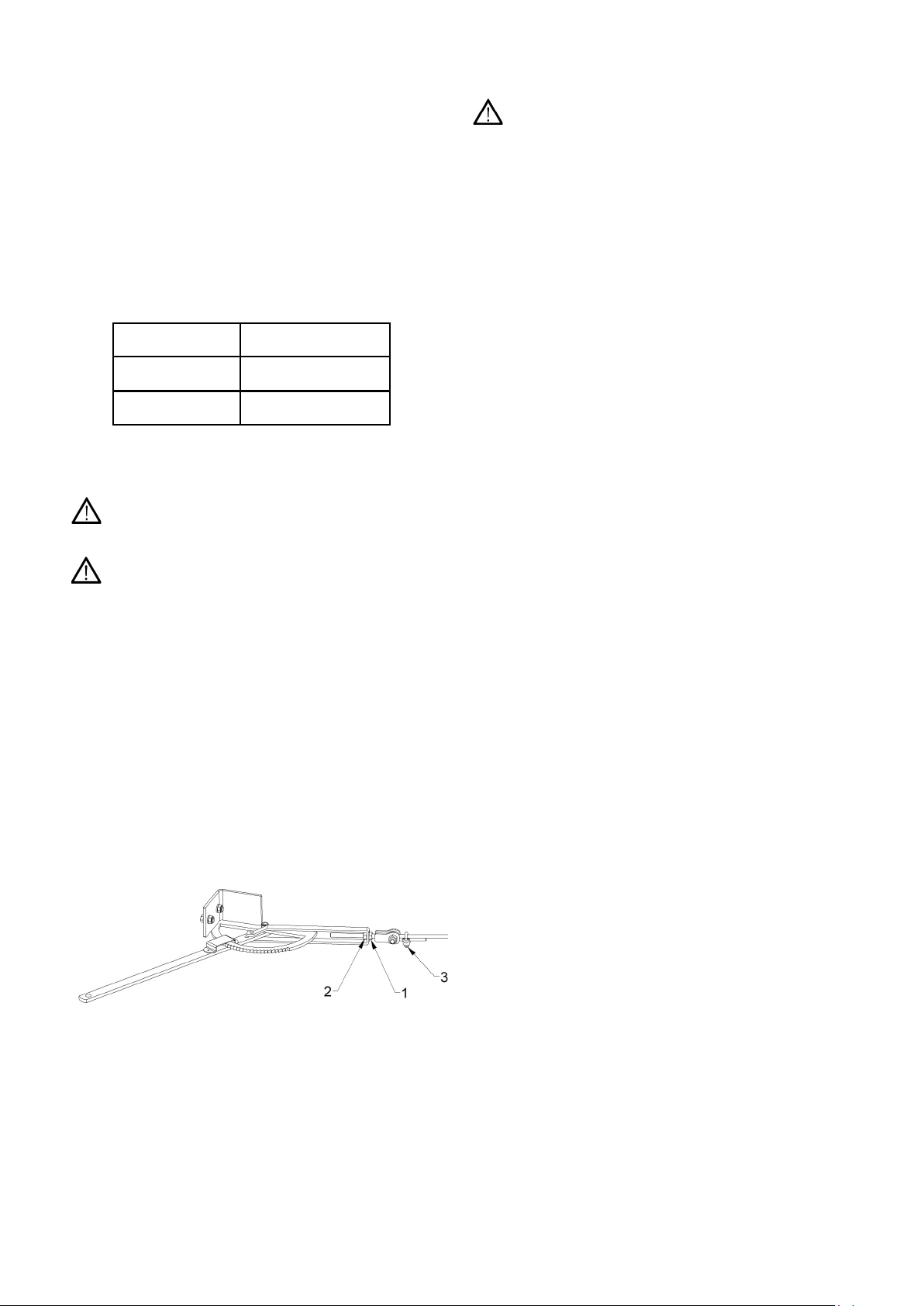
Connect the hydraulic hoses into the spool valve of the
tractor. It is important that the supply hose to the valve
is connected to the pressure port of the tractor, this hose
is marked with red tape around the hose. Attach the
brake hose to the tractor brake coupling
Once the control box has been positioned, route the
machine cable into the cab making sure it is kept away
from the rear wheel and any pinch points between the
PTO shaft and link arms. Where possible, route into
the cab through cable entry points on the tractor,
allowing the rear window to be kept closed during use.
Plug the cable connector into the socket on the box
and lock by the clamp provided.
Ensure the functions of the control box are
completely understood before proceeding to use
the machine. In particular the bed chain is actuated in
the forward direction by pushing the forward direction
button and stopped by pressing the button again.
Reverse of the bed chain can only be actuated by
holding the reverse button.
10. OPERATING INSTRUCTIONS - LOADING
10.1 General
The strings or net should be removed from the
bale as it is being loaded into the machine. The
Tomahawk will shred some string but some will
tend to wrap around the crossbeaters. Putting twine or
netwrap through the machine is not recommended as it
will be eventually spread on the land and polluting
subsequent crops.
When removing string or netwrap from bales never
climb into the bale chamber or onto the tailgate
behind a bale unless the PTO has been disengaged, the
engine has been stopped, the key removed and the
machine come to rest.
5

Bales can be loaded into the machine in two ways, using
a loader or by self-loading using the machine tailgate. If
a loader is used, simply load the bale into the bale
chamber such that it is fully inserted, but do not ram it
against the crossbeaters.
When loading the machine, it will be necessary to
run the bed chain to help self load the bale into the
chamber. However, excessive use of the bed chain for
this purpose may cause material to enter the rotor
housing resulting in a blockage during machine start up.
The tailgate is designed to load bales into the chamber
of the machine. Where a telescopic tailgate is fitted, it is
important to only self load with it in the retracted
position.
To retract the tailgate:
1.) Lower the tailgate.
2.) Switch off the tractor and remove the key.
3.) Remove the extension retaining bolts.
4.) Slide the rear tailgate section towards the machine,
replace the retaining bolts in the retracted position.
Figure 1. Telescopic Tailgate Setting
10.2 Self Loading
Make sure the drawbar is securely attached to the
tractor as self loading may cause it to lift.
For large rectangular bales, place the bale on the
ground with one end against a solid object. For easy
removal of the strings place the bale on its side so that
the strings are not in contact with the ground. In the
case of quadrant bales, place the bale with the knots on
the top. Reverse the machine with the tailgate lowered
until the bale slides up the tailgate into the bale
chamber. Raise the tailgate until it is horizontal and
engage the bed chain to move the bale fully onto the
tailgate.
Make sure that the bale is not forced against the
crossbeaters as this may cause problems when
starting the machine.
Before removing the strings, place the posts in the
sockets on the tailgate and put the chain around the rear
of the bale to avoid the risk of crushing from unsecured
material.
To load round bales, reverse the machine under the
bale so that the bale rests against the tailgate. Lift the
tailgate slightly and drive forward a short distance before
raising the tailgate further. With the bale on the tailgate
cut the strings or netwrap on the machine side of the
bale as low as possible and remove around the top of
the bale. Rope hooks are positioned on the underside of
the tailgate to tie partially removed twine and netwrap to.
Raise the tailgate, the bale will roll into the machine
leaving the twine or netwrap tied to the tailgate allowing
easy removal.
10.3 Multiple Bale Loads
The Tomahawk 1005/1010 are large machines designed
to carry several bales in a load. To maximise the
carrying capacity of the machine it is recommended that
the telescopic tailgate be extended as per Figure 1. A
suitable mechanical loader should now be used for
loading. The machine is now capable of handling two
large rectangular bales 1.2x1.3x2.7m or three 2m round
bales as shown in figure 2 below.
Figure 2. Tomahawk T1005/T1010 Loaded
10.4 Bale Lift
In certain territories (not UK) the machines are available
with a bale lift in the body of the machine to permit a
portion of the load to be lifted from the bed chain. This
can be advantageous in reducing the amount of
material presented to the crossbeaters ensuring smooth
discharge. Operation of the bale lift is by means of the
chute selection buttons on the bottom left of the control
box. When fitted, the feature should be used as shown
in figure 3 below.
Figure 3. Bale Lift Use
6

10.5 Clamp Silage
When loading clamp silage, lower the tailgate slightly to
give a larger body capacity. The hydraulic oil pressure
required to rotate the bed chain will be determined by
the quantity of silage loaded. The machine requires
operating pressures of 120 bar (1750 psi.) when the
body is filled with clamp silage.
11. OPERATING INSTRUCTIONS - DISCHARGE
11.1 Gearbox Speed Selection
The machine is fitted with a 2-speed gearbox. For
blockage free operation it is important that the
correct gearbox speed is selected for the material being
discharged as per table 2 below. The gearbox has a
neutral position, so make sure the required gear has
been properly selected so as not to block the rotor
housing.
Table 2. Recommended Rotor Speed
For shredding straw and other dry materials either rotor
speed may be used, for maximum throw distance the
handle should be moved towards the position marked by
the hare to give a 1:1 ratio between PTO and discharge
rotor speed.
For shredding silage and other wet materials it is
recommended that the slow rotor speed be used since
long throw distances are not usually required To set the
slow rotor speed, the gearbox handle should be moved
to the position marked by the tortoise to give a 1.85:1
ratio. The machine may be used at reduced PTO
speeds and still deliver material to the desired position.
Very low PTO speeds should be avoided as a blockage
in the rotor housing may result.
11.2 Right Hand Chute
Adjust the position of the chute to deliver the material
being spread in the desired location, typically this will be
down beside the machine for feeding and elevated for
bedding.
11.3 Sloping Swivel Chute
The swivel chute rotates through 300 degrees and can
be operated to either side of and behind the machine.
To deliver silage close to the machine position the
chute so that material is delivered onto the feed
passage slide, the position of the slide can be adjusted
to deliver the material accurately. Alternatively the
position of the material can be controlled by the chute,
it may be necessary to rotate the chute fully delivering
material alongside the drawbar.
The discharge of baled silage along the left hand
side of the machine is not recommended.
In transport, rotate the chute to the right hand side of
the machine aligning the indicators on the chute and
top housing. Fully lower the deflector to keep the width
and height of the machine to a minimum.
11.4 Engaging PTO
Engage the PTO with the tractor engine on low idle and
increase the speed rapidly to working speed when the
clutch has engaged fully.
11.5 Before Commencing Discharge
If the machine is loaded to capacity, i.e. material other
than clamp silage is supported by the tailgate, the
tailgate must remain horizontal until the material in the
body has been discharged. This is necessary to allow
the material within the body of the machine to rotate
freely once it comes into contact with the crossbeaters.
No attempt should ever be made to force material
towards the crossbeaters using the tailgate. With the
bed chain speed control on the control box on zero,
engage the tractor spool valve and switch the bed chain
on in the forward direction by pressing the bed chain
forward button once. General discharging instructions
follow after the specific round/square bale and clamp
silage instructions below.
11.6 Discharging Square Bales
Gradually increase bed chain speed by means of the
speed control until shredding commences. It is then
advisable to increase bed chain speed to a point at
which the slices of the bale being shredded are forced
up and over the material coming forward. This rotational
motion is represented in figure 4 below.
Figure 4. Rotation Of Square Bales
Where a bale lift is fitted, release the portion of the bale
retained only when the first portion has been discharged
which is usually indicated by a large fall in discharge
rate.
Once the material in the bale chamber has been
discharged the tailgate can be lifted to allow the second
bale (or a portion of) to be loaded into the chamber. It
will be found advantageous to only allow half of the
second bale to enter the chamber at a time thus allowing
room for each half to rotate.
Typically the rate of discharge may be controlled by bed
chain speed but only once rotation of the material within
the body of the machine has been achieved in the first
instance.
11.7 Discharging Round Bales
Gradually increase bed chain speed by means of the
speed control until discharge commences. Good
performance will only be achieved by getting the bale to
rotate within the chamber as shown in figure 5 overleaf.
Increasing the speed of the bed chain will increase the
rate of discharge until a maximum rate is achieved. If the
bed chain speed is too great, material will unroll from the
bale at a rate greater than can be discharged. This will
7
Material Distance
Spread Gearbox
Speed PTO Speed
Straw Maximum High 540
Straw Close High 300
Baled Silage Close Low 540
Clamp Silage Close Low 300

be indicated by a build up of material above the bale
restraint.
Figure 5. Rotation Of Round Bales
11.8 Discharging Clamp Silage
Increase bed chain speed until the desired discharge
rate is achieved. Once the forward portion of the load
has been discharged, the tailgate can be lifted to ensure
a continuous feed rate.
11.9 General Discharging Instructions
If a large amount of loose material builds up above the
bale restraint it may be necessary to reverse the bed
chain until the loose material falls down behind the
crossbeaters before commencing discharge.
When it is necessary to stop shredding part way through
a bale, always stop the bed chain rotation and put it in
reverse for a few seconds before stopping the rotor and
crossbeaters. This allows the material in the area
around the crossbeaters and rotor to be blown clear of
the machine. Failure to do this may result in a blockage
occurring when the machine is re-started.
The length of chop will vary with the condition of the
bale. The evenness of feed and power consumption will
also vary with the material being shredded. In general,
baled silage and damp or caked straw materials will
require a higher power input than dry brittle materials.
Should the rotor or crossbeaters become blocked
indicated by either slipping of the PTO clutch or failure of
the crossbeaters shear bolt, it may be necessary to turn
the rotor backwards. This may be achieved by levering
the rotor paddles with a post through the outlet chute.
Further access may be gained by removing the
blockage panels from the front of the upper and lower
rotor housing.
12. MACHINE PROTECTION DEVICES
IMPORTANT: The machine is fitted with a shear bolt on
the cross beater drive line. After a blockage, the bolt
may need replacing. If the bolt has failed grease must
be applied to the slipping surfaces via the grease nipple
before the shear bolt is replaced.
IMPORTANT: The machine is fitted with a slip clutch on
the PTO shaft. If this slips repeatedly, it should not be
tightened until the machine has been examined to check
that there is no fault or blockage. Refer to 'Maintenance'
for the correct clutch setting.
The slip clutch may be hot. Care should be taken
when removing it from either the machine or tractor.
13. MAINTENANCE
13.1 Safety
Never climb into the bale chamber or onto the
tailgate unless the PTO has been disengaged. The
engine has been stopped, the key has been removed
and the machine has come to a rest.
Care must be taken when carrying out any
maintenance on / around the chopping blades as
they are extremely sharp. Leather gloves will give some
protection against minor cuts.
13.2 Blades
When carrying out maintenance work on the blades
enter the bale chamber via the tailgate. Wedge the rotor
and crossbeaters to prevent them from turning reducing
the risk of trapping hands between the knives and bale
restraint fingers. When replacing knives use spanners
with long handles which will allow the bolts to be
removed whilst avoiding contact with the sharp edges of
the knives.
Always keep your hands away from the edges of
blades - particularly new ones, as they are
extremely sharp. The blades have a sharp trailing edge,
which remains sharp even when the leading edge is
blunt.
13.3 Bed Chain
To tension the bed chain, release the front lock nut on
the tensioner and jack the tensioner using the other nut.
The bed chain should be tensioned such that the chain
can be lifted 50mm above the bed midway between the
drive sprockets. Retighten lock nuts after tensioning.
The chain tension must be checked and adjusted
after initial use as bedding in shall occur.
If the Bed Chain becomes tight in use, check that the
grooves in the Chain Wheels have not become tightly
packed with straw or silage. If they have they need
clearing and the condition of the Scrapers needs to be
checked.
If the area beneath the Bed Chain becomes blocked or
requires attention, remove the bolted Inspection Panels
underneath the machine and clear the blockage.
Check the Front Scrapers for excessive wear, these
may require replacing over time.
Figure 6. Sprocket Scraper Position
13.4 Crossbeater shear bolt
To replace the shear bolt, open the hinged LH drive
chain guard. The shear bolt is on the lower crossbeater
shaft. Grease the hub before replacing the shear bolt
with a Grade 10.9 M8 x 50 bolt.
8

13.5 Gearbox
After 50 hours of use the gear box oil should be drained
and replaced with new oil. To drain the oil, remove the
PTO shaft and guard cone remove the drain and filler
plugs and allow it to empty. Waste oil should be
collected and disposed of at an oil recycling facility
Refill the gearbox to the level plug with SAE90.EP
gearbox oil. The oil capacity of the gearbox is 4.7ltrs
13.6 Drive Chains
Apply chain lubricant or oil weekly. The chains should be
tensioned so that there is 12-13mm (1/2”) deflection at
the mid span point as indicated in figure 7 below.
Figure 7. Chain Deflection
To tension the crossbeaters drive chains, open the
hinged chain guard on the left hand side of the
machine. For the lower beater drive, slacken the
layshaft bearing bolts and tensioner locknut. Increase
tension by jacking the bearing as required until the
correct tension condition is met. Retighten all nuts. For
the upper crossbeater slacken the tensioner roller
mounting bolt in the centre of the roller and turn the
tension screw on the adjuster clockwise until the
correct tension condition is met. Retighten the roller
mounting bolt.
13.7 Swivel Chute
The chute is rotated by means of a gear and ring gear.
It is important that this is well greased. To apply grease
to the ring gears there are 4 grease nipples on the
mounting flange.
The deflector ram has 2 grease nipples, one on each
pivot bush.
13.8 Hydraulics
Before attempting to dismantle any of the hydraulic
system, the tailgate and deflectors must be fully
lowered to prevent injury from the unexpected lowering
of these components.
The hydraulic system is protected from contamination by
an inline pressure filter. Periodically the element should
be checked for contamination and it is recommended
that the element be replaced at least once annually. To
replace the element, remove the guard covering the
hydraulic valve on the front right of the machine and
unscrew the filter canister. Replace element, retighten
canister and fit valve guard.
If problems are experienced with either the hydraulic
system or electric controls, please contact Teagle
Machinery Ltd. for advice as a separate manual is
available to cover troubleshooting and repair.
13.9 PTO Slip Clutch
If the clutch slips repeatedly for no apparent reason
there are a number of things to be checked:
Firstly check that the clutch linings do not show signs of
damage or excessive wear. If so, they should be
replaced. When new they are 3mm. (1/8") thick.
Also make sure that the compressed spring length is set
to give the correct torque setting – see PTO shaft parts
list.
If the clutch continues to slip it should be adjusted as
follows:
1 Remove the guard fitted to the rotor gearbox.
2 Fit the PTO shaft with the slip clutch at the machine
end.
3 Insert a piece of wood through the discharge chute
and position it such that it prevents the rotor from
turning.
4 Insert a steel bar through the rear PTO yoke and use
a spring balance to obtain the correct torque setting.
The clutch should just slip at a torque of 1200 Nm.
(900 lb.ft.) - equal to a force of 1000N. at 1.2 metre
(225 lb. at 4 feet) from the centre of the yoke. Adjust
the clutch as necessary using the eight spring loaded
clamp bolts.
13.10 Lubrication
Good quality semi-solid grease should be applied to the
following grease points:
The above lubrication frequencies are based on typical
daily use for bedding & feeding purposes. Continuous
use for special applications may require more frequent
lubrication.
9
Greasing / Oil See separate Chart
PTO and clutch Lubricate as Chart
Dismantle Clutch at Start of
Season
Gearboxes Replace main gearbox oil after
first 50 hours then check
monthly. Where fitted, check
bed chain drive gearbox
monthly
Remove stones Each Bale Or Daily,
Depending On Use And Na-
ture Of Bales
Bed Chain
Tension After First Day Then
Weekly Depending On Use
Crossbeater Chain
Tension Weekly
Clean above
inspection Panel Monthly, Depending On Use
Tyre pressures &
Wheel nuts Monthly
Option – Replace
oil filter Yearly
Blades As Required

13.11 Wheel Nuts
Before using a new machine and daily during use, check
the wheel nuts are tight. They should be torqued to a
value of 400Nm (320 lb ft).
Once the nuts are allowed to work loose, it may be
found impossible to keep them tight and new nuts and
studs will be required to overcome the problem. In
extreme cases, damage to the wheel rims and hubs
may result.
13.12 Tyre Pressure
Check the tyre pressures regularly inflating them to the
pressures in table 3 overleaf as required.
Table 3. Tyre Pressures
13.13 Replacing Wheels
If it is necessary to remove a wheel, place a jack
underneath the axle beam, loosen the wheel nuts
and raise the machine until the wheel can be removed.
Place an axle stand underneath the machine
before removing the wheel. Refit the wheel and
tighten the wheel nuts.
13.14 Electric Controls.
The electric controls require no maintenance and it is
imperative that no part of the system is ever sprayed
with a moisture repelling agent such as WD40.
If a malfunction of the system occurs, please contact
Teagle Machinery Ltd or an authorised dealer/distributor
for advice.
13.15 Handbrake Adjustment
With reference to figure 8 below, the handbrake can be
adjusted by releasing the locknut (item 1) and increasing
tension by means of the tension nut (item 2). If
maximum travel is reached then the clamp (item 3) can
be released and the rope adjusted accordingly.
Figure 8. Handbrake Adjustment
13.16 Service Brake Adjustment
It is imperative that the brakes are adjusted
correctly to meet the requirements of the current
braking regulations. As the brake shoes wear, it may be
necessary to realign the actuating rods on their splines
so that the arms are perpendicular to the ram body.
13.17 Removal Of Main Rotor
The rotor can only be released from the main gearbox
with the application of service tool SC3776 available
from the manufacturer.
14. OPTIONAL EXTRAS
14.1 Drawbar Jack
Where the machine is fitted with a drawbar jack, adjust
the height of the drawbar to match the height of the hitch
point on the tractor. Reverse the tractor and attach the
drawbar. Lower the machine until the weight is fully
transferred to the tractor. Remove the pin retaining the
jack to the drawbar and transfer it onto the transport
position across the front of the chassis.
15. MACHINE STORAGE
When the machine is not being used it is
recommended that the control box be stored safely
away from the machine in a dry location. The electrical
connections together with hydraulic hoses should be
stored in the positions provided on the layshaft guard
on the front right of the machine. If the machine is to
be laid up for any great length of time it should be
thoroughly cleaned down and any bright surfaces
treated with paint as opposed to a rust preventative
since the machine is used for dispensing foodstuffs. All
lubrication points should be attended to ready for
subsequent reuse.
16. DISPOSAL
At the end of the machine’s working life, the method of
disposal must be within the legislation laid down by the
local authority or the National Environment Agency.
The machine is composed of ferrous materials,
synthetic paints and rubber compounds.
10
Tyre Size Pressure bar (psi)
285/70R19.5 5.8 ( 84)
405/60 R22.5 5.8 ( 84 )

11
TOMAHAWK FAULT FINDING CHART – PART 1
Symptom Fault Possible Solutions
High power
consumption Bale fed too quickly into crossbeaters.
Knives too aggressive
Reduce bed chain speed.
Slope knives backwards using holes provided
Rotor will not
start Bale forced against crossbeaters. Reverse bed chain.
Material in rotor housing jamming rotor. Reverse rotor to clear blockage.
Clutch setting too low. Check setting and adjust.
Bed chain will not
turn Hydraulic valve problem. See section below.
Material jammed between bed chain
and bodywork. Clear material and check bed chain tension.
Relief valve setting too low. Adjust relief valve or replace if the spring is worn.
Tractor hydraulic oil pressure low. Check pressure delivered by tractor.
Bed chain has come off the sprockets. Check sprocket condition, replace the bed chain and
tension it.
Bed chain broken. Check sprocket groove is clean and that the
chamber below the floor is free from obstructions.
Repair chain and refit.
Motor not turning. Check connections and tractor hydraulics. If motor is
seized reverse flow to release. Consult your dealer if
this fails.
Bed drive chain has come off the
sprocket. Check sprocket condition, replace the chain and
tension it.
Sprockets seized. Replace bearings.
Bed Chain speed too slow. Increase forward speed of bed chain using flow
control valve.
Slow discharge
Insufficient aggression of knives Check knives to see if they are in aggressive
position on crossbeaters
Blades blunt or worn. Sharpen, reverse or replace blades.
Material jammed hard against bale
restraint above crossbeaters. Reverse bed chain direction for at least 5 seconds
until feed is restored.
Rotor speed low. Check that slip clutch is not slipping - indicated by
hot clutch assembly.
Rotor speed low. Check tractor tachometer.
Bale stops
discharging Crossbeaters not rotating. Replace shear bolt in drive sprocket.
Gearbox in neutral. Remove material from rotor housing before
restarting and select correct gear.
Bed chain not rotating. See Above.
17. FAULT FINDING

TOMAHAWK FAULT FINDING CHART – PART 2
Symptom Fault Possible Solutions
Shear bolt fails
repeatedly. Bolt bushes worn or damaged. Replace with new bushes.
Tailgate raised too high forcing bale into
crossbeater(s). Lower the tailgate to allow material in bale chamber
to rotate freely.
Front half of large rectangular bale not
rotating freely. Lower the tailgate to allow material in bale chamber
to rotate freely and increase the bed chain speed to
encourage rotation of the front half of bale.
Single beater
shear bolt fails
repeatedly
One or more bale restraint fingers bent
and interfering with crossbeater. Straighten or replace damaged bale restraint finger.
Twin beater
shear bolt fails
repeatedly
Long dry material wrapping around
crossbeater(s) and bale restraint. Consult manufacturer.
Chute and rotor
blocks Chute exit blocked. Make sure material can leave the chute freely.
Rotor speed low. Check that slip clutch is not slipping
Select high rotor speed on gearbox
Swivel giraffe
chute blocks Material not flowing smoothly. Raise deflector to improve flow and rotate chute to
achieve desired delivery position.
Rotor speed low. Check high rotor speed selected on gearbox.
Hydraulic valve
fails to operate Hydraulic connections to tractor faulty or
not connected. Rectify making sure pressure is applied to the valve
via the supply hose and that the return line flow is not
restricted.
Bed chain no
longer operates
or only very
slowly. Failure
may be sudden
or intermittent.
Dirt or contamination in the Bypass
Valve or the Pressure Relief Valve in the
flow control slice.
Firstly, remove the Bypass Valve from the Flow
Control Slice inspect for contamination clean and
replace. If problem still exists, remove the Pressure
Relief Valve and inspect for contamination. If
problem persists or re occurs regularly replace tractor
hydraulic oil with new clean oil.
Loss of
operation of
rams and swivel
slices. Also
operation of bed
in only 1
direction may
occur. Failure
may be sudden
or deteriorate
slowly over a
few days.
Oil leaking from between slices of the
valve.
Failure of pilot cartridge through
contamination
See section below.
Contact manufacturer for advice.
Internal pressure in valve. Check return line hose connected and that return line
flow is not restricted by damaged fittings or the
tractor spool valve
Oil leaking from
between slices
of the valve.
Clamping bolts loose. Check bolts through valve tightened to correct torque
specified in the maintenance section.
Interface seals damaged by either of the
above. Replace damaged seals.
12

13
CHUTE RAM Closed centres 386, Open centres 642, Stroke 256.
Ram assembly CYL1084 1
Seal kit (items 4, 5, 8 & 10) HYD4860 1
1Piston CYL1075 1
2Cylinder body CYL1082 1
3Restrictor 0.8mm dia HYD1746 2
4Rod seal 25mm HYD4496 1
5Wiper seal 16mm HYD4524 1
6Piston rod CYL1083 1
7Wiper seal housing CYL1077 1
8"O" ring B.S. 216 HYD4039 1
9Rod seal housing CYL1076 1
10 "O" ring B.S. 017 HYD4033 1
11 Piston seal 40mm dia. HYD4431 1
12 Grease Nipple ¼ “ BSF BRG5004 2
Ref. Description Part No. Qty. Ref. Description Part No. Qty.
TAILGATE RAM (With Pilot Operated Check Valve)
Closed centres 571, Open centres 971, Stroke 400
Ram assembly CYL1135 2
Seal kit (items 1,10,11,13 & 14) HYD4813 1
(Check valve seals not included, see item 16)
1Wiper seal HYD4517 1
2Wiper seal housing CYL1004 1
3Rod seal back up ring DC1233 1
4Cylinder assembly CYL1136 1
5Piston rod CYL1067 1
6Piston body CYL1138 1
7Piston end CYL1139 1
8Restrictor 1.3mm HYD1746 1
9Locknut M20 FAS2336 1
10 Seal HYD4498 1
11 "O" ring HYD4007 1
12 Rod seal housing CYL1137 1
13 "O" ring HYD4050 1
14 "U" packing HYD4327 1
15 Pilot operated check valve CYL1128 1
16 Check valve seal kit (not shown) HYD4870 1
18. PARTS LIST

14
BRAKED AXLE
Ref. Description Part No. Qty. Associated Components Part No. Qty.
1Ratchet handbrake assembly SC4880 1Setscrew M10 x 25 FAS2654P 2
Plain washer M10 FAS2344P 2
Locknut M10 FAS2333 2
2Handbrake adjuster SC4866 1Bolt M12 x 40 FAS9680P 1
Rope Collar TRM1038 1
Locknut M12 FAS2334 1
Plain nut M10 FAS2303P 2
3Handbrake cable SC4909 1Rope Grip 8mm ROP1291 1
4Brake equaliser SC4917 1Bolt M12 x 45 FAS9681P 1
Locknut M12 FAS2334 1
5Braked axle SC4801 1Bolt M20 x 140 FAS9742P 4
Plain washer M20 FAS2347P 4
Locknut M20 FAS2336 4
6Wheel 385/55 R22.5 8 Stud WE1270 2
7Wheel nut WE0909 8
8Mudguard RH SC4906 1Setscrew M12 x 45 FAS2681P 2
Setscrew M12 x 30 FAS2678P 2
Plain washer M12 FAS2345P 8
Locknut M12 FAS2334 4
Cup Square M10 x 25 FAS9262P 2
Plain washer M12 FAS2345P 2
Locknut M10 FAS2333 2
9Mudguard LH SC4905 1Setscrew M12 x 45 FAS2681P 2
Setscrew M12 x 30 FAS2678P 2
Plain washer M12 FAS2345P 8
Locknut M12 FAS2334 4
Cup Square M10 x 25 FAS9262P 2
Plain washer M12 FAS2345P 2
Locknut M10 FAS2333 2
10 Brake cylinder TB1101 1Seal kit - Brake ram 35mm CYL1212 1
11 Brake return spring (185 x 3.3) SPR4612 2

15
Ref. Description Part No. Qty. Associated Components Part No. Qty.
1Chassis SC4800 1Setscrew M12 x 25 FAS2677P 2
Locknut M12 FAS2334 2
2Front Plate LH SC4807 1Setscrew M10 x 25 FAS2654P 1
Plain washer M10 FAS2344P 1
Locknut M10 FAS2333 1
3Sealing Strip SC4610 1Setscrew M10 x 25 FAS2654P 7
Locknut M10 FAS2333 7
4Clamp Plate SC4621 1
5Front Plate RH SC4808 1Setscrew M10 x 25 FAS2654P 1
Plain washer M10 FAS2344P 1
Locknut M10 FAS2333 1
6Front Lower Panel SC4806 1Setscrew M10 x 20 FAS2652P 5
Cup Square M10 x 25 FAS9262P 4
Plain washer M10 FAS2344P 9
Locknut M10 FAS2333 9
7Chain Runner SC4931 2Cup Square M12 x 30 FAS9283P 8
Plain Washer M12 FAS2345P 8
Locknut M12 FAS2334 8
8 Front Lower Inspection Panel SC4927 1Setscrew M10 x 25 FAS2654P 2
Plain washer M10 FAS2344P 2
Locknut M10 FAS2333 2
9Middle Lower Inspection Panel SC4928 2Setscrew M10 x 25 FAS2654P 4
Plain washer M10 FAS2344P 4
Locknut M10 FAS2333 4
10 Rear Lower Inspection Panel SC4929 1Setscrew M10 x 25 FAS2654P 2
Plain Washer M10 FAS2344P 2
Locknut M10 FAS2333 2
Cup Square M12 x 30 FAS9283P 2
Plain Washer M12 FAS2345P 2
Locknut M12 FAS2334 2
11 Hinged Inspection Panel SC4930 1Sealing Pin 1167-9FAS6033 2
12 Tailgate Ram CYL1135 2Tailgate Pivot Pin TRM0738 2
Tailgate Ram Pin SC4911 2
Spring Tension Pin FAS4131 6
CHASSIS

16
Ref. Description Part No. Q’ty. Associated Components Part No. Q’ty.
Rotor c\w Paddles SC4617 1Item 1 & 2
1Paddle (5 Bolt Fixing) SC4616 8Setscrew M12 x 30 FAS2678P 48
Locknut M12 FAS2334 48
2Rotor SC4502 1Setscrew M14 x 45 FAS2696P 1
Washer 75 x 15 x 10 FAS4805P 1
3Front Housing
From serial No 1509 & 3524 SC4670 1
4Sprocket 14 Tooth (Silage) SC3356 1Key 10 x 8 x 40 FAS8120 1
Sprocket 25 Tooth (Dual Chop) SC4556 1Setscrew M10 x 30 FAS2655P 1
Spring washer M10 FAS2354P 1
Washer 45 x 10 x 5 FAS2412P 1
5Flange Bearing 1 3/8”BRG1305 1Grease Nipple M6 Straight BRG5030 1
Setscrew M12 x 35 FAS2679P 2
Plain Washer M12 FAS2345P 2
Locknut M12 FAS2334 2
6Drive Adjustment Plate SC4120 1Setscrew M16 x 70 FAS2709P 1
Plain nut M16 FAS2305P 1
Locknut M12 FAS2334 2
7Layshaft - Splined Yoke SC4620 1End Yoke PTO2794 1
Cross Journal Kit PTO2321 1
Setscrew M12 x 80 FAS2688P 1
Plain Nut M12 FAS2304 1
FRONT HOUSING & ROTOR
Table of contents
Other Teagle Farm Equipment manuals

Teagle
Teagle Tomahawk 808S User manual

Teagle
Teagle Tomahawk 8500 User manual

Teagle
Teagle Tomahawk 7100 User manual

Teagle
Teagle Telehawk Installation and operation manual

Teagle
Teagle Tomahawk 8080S User manual

Teagle
Teagle Tomahawk 404M User manual

Teagle
Teagle Telehawk User manual

Teagle
Teagle Tomahawk 404M User manual

Teagle
Teagle Tomahawk C12 User manual

Teagle
Teagle Tomahawk C12 User manual
Popular Farm Equipment manuals by other brands

Avery Dennison
Avery Dennison Eartrace RH7 Quick start quide

BSL
BSL strautmann Zelon CFS 2501 Translation of the original operating instructions

TMG
TMG TMG-CRS1060 product manual

Schulte
Schulte SMR-600 Operator's manual

Landoll
Landoll 4620-24 Operator's manual

EasySwing
EasySwing Totem TT001-X1 User instructions