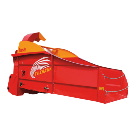
Teagle Telehawk User manual

_ _ _ _ _ _ _ _ _ _ _ _

Ref. Description
1Grease Nipple – Rear
Bed Chain Roller Bush
2Grease Nipples x 2 – At
ends of SC Chute Ram
Ref. Description
3Grease Nipples x 4 –
SC Swivel mechanism
Ref. Description
4Grease Nipple - Cross
beater bearing
5Grease Nipple - Bed
Chain front roller
bearing
For More Detailed Information See Pages 10 to 11
1.
3.
2.
4.
5.
1.

EC Declaration of Conformity
conforming to EEC Directive 2006/42/EC
Teagle Machinery Ltd.
Blackwater
Truro
Cornwall
TR4 8HQ
United Kingdom
declares in sole responsibility that the
TELEHAWK
Spreader
to which this certificate applies
conforms to the essential Health and Safety requirements of
EEC Directive 2006/42/EC & 2004/108/EC.
To effect correct application of the essential
Health and Safety requirements stated in
the EEC Directives, the following harmonised standards were consulted:
BS EN ISO 12100-1
BS EN ISO 12100-2
BS EN ISO 13857:2008
BS EN 703:2004 + A1:2009
Signed:
Duncan Wilson (Engineering Director)
Dated: 9th May, 2014
Person authorised to compile Technical File
Duncan Wilson,
Teagle Machinery
Blackwater, Truro
Cornwall, TR4 8HQ
United Kingdom
Machine Serial No. . . . . . . . . .

SAFETY FIRST!
1. READ THE INSTRUCTION BOOK THOROUGHLY
before attempting to operate or carry out any
maintenance on the machine. If you do not
understand any part of this manual, ask your dealer
for assistance.
2. ALWAYS CARRY OUT SAFE
MAINTENANCE. Never clean, adjust or
maintain the machine until the engine has been
stopped, the machine come to rest, lowered to the
ground and the key removed.
3. NEVER WORK UNDER A MACHINE
RAISED ON THE LOADER unless it is
securely supported.
4. NEVER OPERATE THE MACHINE WITH ANY
PARTS OR GUARDS MISSING. Check that all
guards are in good condition and in place before
operating the machine.
5 OPERATE SAFELY. Before starting work, check
that there are no persons or animals in the
immediate vicinity of the machine or loader. Always
maintain full control of the loader and machine.
Ensure that you know how to stop the loader and
machine quickly in case of emergency.
6. NEVER STAND BETWEEN THE MACHINE
AND THE LOADER WHEELS.
8. DO NOT WEAR LOOSE OR RAGGED CLOTHING
9. BEWARE OF DUST. Under dusty conditions,
keep the cab windows and doors closed. The use of
a dust mask conforming to EN149 is strongly
recommended.
10. BEWARE OF HIGH NOISE LEVELS. Some
loader/implement combinations give noise
levels in excess of 90dB at the operator's ear.
Under such circumstances, ear defenders
should be worn. Keep cab windows and doors
closed to reduce noise level.
Throughout this handbook, the term `loader' is used to
refer to the power source used to drive the machine. It
does not necessarily refer to a conventional agricultural
loader, telescopic handler or loader.
HEALTH AND SAFETY AT WORK
Our equipment is designed so as to conform with
current Health & Safety Regulations and therefore
poses no significant hazard to health when properly
used. Nevertheless, in the interests of all concerned, it
is essential that equipment of our manufacture is used
in accordance with the instructions that are supplied or
are available from our Technical Staff.
Legislation requires that all operators are instructed in
the safe operation, cleaning and maintenance of
equipment and machines. This handbook forms part of
that instruction and it must be read and understood
before fitting the machine onto the loader or attempting
to use it.
Your supplier is responsible
for carrying out any necessary pre-delivery inspection,
fitting the machine onto the loader and test running.
The supplier must also give instruction in the safe use,
maintenance and adjustment of the machine.
In the interests of safety, please ensure that the
instructions referred to above are brought to the
attention of all your employees who are to use the
equipment. We recommend that the use of this
equipment is restricted to capable trained operatives.
Persons under the age of sixteen should not operate the
machine and should be kept away from where it is being
used.
WARRANTY
The standard warranty is against faulty materials and
workmanship. Components supplied as part of the original
machine, but manufactured by another company, e.g.
hydraulic motors, valve blocks etc, are subject to the
original manufacturer's conditions and warranty.
Where repairs are carried out under warranty:-
a) Claims for the fitting of non original parts will not be
considered unless prior agreement has been obtained.
b) The repairer must be advised that the work is to be the
subject of a warranty claim beforehand.
c) Any claim must be submitted within four weeks of the
repair.
d) The damaged parts must be retained for inspection and
returned carriage paid if required.
The right to withdraw warranty is reserved if:-
a) Non-original parts are fitted.
b) The machine has been abused, badly maintained or
used for purposes other than that for which it was
designed.
INDEX
INSTRUCTIONS Page
Specifications 2
Explanation of pictograms 2
Decals 2
Safety 4
Left and right hand 4
Use of the Telehawk 4
Use on the public highway 4
Loader Specification 4
Fitting the junction box onto the loader 5
Fitting the control box onto the loader 5
Preparation of the Telehawk 5
Fitting the Telehawk onto the loader 5
Operation 5
Commencing Operation 6
Maintenance 7
Disposal 9
FAULT FINDING CHART
Part 1 10
Part 2 11
PARTS LISTS
Decals 3
Body 12
Top housing 14
Chute ram 15
Crossbeater & drive 16
Floor assembly 18
Inline Oil Filter 19
Bed chain speed adjustment 20
Electric controls 21
Transport brackets 21
Hydraulic hoses 22
Solenoid\electric control valves 23
1

SPECIFICATIONS
Specifications TELEHAWK
Chamber Width 1.4m
Swivel Chute Discharge Height 2.4m
Swivel Chute Rotation Angle 280 degrees
Overall Width (Chutes Closed) 1.69m
Max. Overall Width 1.69m
Overall Height - Max 2.52m
Overall Height - Min 2.41m
Overall Length - (without brackets) 3.70m
Max. Round Bale Diameter 1.50m
Max. Rectangular Bale Size 1.2m x 1.2m x 2.5m
Weight (without brackets) 1270kg
Max. Hydraulic Oil Pressure 210 bar
Max. Hydraulic Oil Flow 125 litres/minute
Min. Hydraulic Oil Flow 65 litres/minute
Time Averaged Sound Power 92dBA
Minimum Loader Size 2.6 tonne lift
Vertical Load At Hitching Point -Un-laden 1360kg
Vertical Load At Hitching Point -Laden 1860kg
2
Do Not Allow Any One To Ride
On The Machine Please Read Instruction Book
Before Using The Machine
Beware Thrown Objects
Keep Your Distance
EXPLANATION OF PICTOGRAMS
Loader Control Box Panel

33
Allow Rotor To Stop Before Removing
Blockage With Tool Provided
Maximum Hydraulic Circuit Pressure
Max Flow And Direction Blockage Removal Tool
DECALS
Description Part No. Q’ty Description Part No. Q’ty
Teagle - front housing DL1320 1Do not permit riders DL1036 2
Teagle - sides DL1389 2Read instruction book DL1006 1
Telehawk DL1393 2Blockage removal tool DL1070 1
Swish LH DL1383 1Fingers being severed DL1033 2
Swish RH DL1384 1Thrown objects DL1039 1
Serial number plate DL2059 1Pop rivets FAS9069 2
Max flow 125 lpm DL1390 1Max pressure DL1391 1
* Important Note: 27.5 Imp Gal/
min = 33.0 US Gal/min

SAFETY
In addition to the standard safety guidelines listed at the
beginning of this handbook, the following special safety
items apply to the Telehawk.
1 The machine shall be operated by one person
only.
2NEVER put your hands inside the delivery
chutes. In the event of a blockage clear it
using the Blockage Removal Tool provided,
located on the front of the lower housing. First,
disengage the hydraulic pump, lower the machine to
the ground, apply the handbrake, stop the engine,
remove the key, and wait for the rotor to come to
rest.
3 NEVER enter the bale chamber unless the
machine has been lowered to the ground, the
engine has been stopped with key removed
from the ignition, and the machine has come
to rest (see note 2 above).
4 NEVER insert anything inside the chute or
bale chamber while the machine is running.
5 DANGER. When entering or leaving the
bale chamber take care, the floor surface may
be slippery.
6Beware of overhead power lines when the
swivel chute deflector is fully raised. Contact with
power lines could result in the operator receiving a
severe electric shock.
7Do not climb onto the top edges of the bale chamber
whilst the machine is in use.
8Do not allow anyone to ride on the machine.
9Do not allow persons or animals to stand in front of
the outlet chutes whilst the machine is running.
10 Do not lower the machine if any person or animal is
standing in the loading area in front of the machine,
always ensure good forward visibility when lowering
the machine.
11 Never put your hand over a hydraulic leak. Oil under
pressure may enter the blood stream.
12 The spreading of dusty or mouldy material can
create dust which may have adverse health effects.
Operator exposure to such conditions should be
avoided where possible. When circumstances
prevent this, either use a loader with a suitable
forced air cab filtration system or an adequate
respirator. Respirators must comply with the relevant
Standard and be approved by the Safety
Inspectorate. Disposable filtering face piece
respirators to EN149 or half mask respirators to
EN140 fitted with filters to EN 143 are likely to be
adequate.
13 Before disconnecting the hydraulic hoses always
lower the machine onto the ground for safety
reasons and to avoid residual pressure in the hoses.
14 Care must be taken when handling large bales, as
they have sufficient weight and density to cause
serious injury. Large bales should be handled with
appropriate machinery either directly into the
Telehawk or into a position where they can be self
loaded. Do not manually load bales from the stack
above the machine, so as to prevent the risks of
falling into the machine and collapse of the stack of
bales.
15 Caution after prolonged intensive use of the machine,
the oil temperature will have risen causing the hoses
and fittings to be hot.
LEFT AND RIGHT HAND
In this Handbook and Parts List, the terms Left and
Right Hand apply to the machine when viewed from the
drivers seat of the loader.
USE OF THE TELEHAWK
The machine is designed to spread only dry straw bales.
The machine must never be run with the chute
components removed. Unapproved chute modifications
should not be carried out as Safety Regulations may be
infringed.
USE ON THE PUBLIC HIGHWAY
If the machine is attached to the front of the loader it is
not recommended that the loader is driven on a public
highway.
If the machine is to be transported along the public
highway (any road where the public have access)
behind the loader, it may be necessary to fit lights
to comply with local road traffic legislation, as the
machine is likely to obscure the loader rear light units.
Suitable lighting kits are available from your local
supplier or may be obtained by contacting Teagle
Machinery.
Failure to comply with road traffic legislation may lead to
prosecution by local law enforcement agencies and
could also result in a road traffic accident.
LOADER SPECIFICATIONS
Lifting capacity: Minimum of 2.6 tonnes.
Oil flow: Minimum oil flow of 60 litres per min (13.3
gallons per min). Maximum oil flow of 120 litres per min
(26.6 gallons per min).
Oil pressure: Minimum of 160 bar (2320 psi). Maximum
of 270 bar 3915psi @ 80 °C (176 °F)
Return line pressure: Maximum 20 bar (290psi).
The hydraulic system requires a single acting valve with
an unrestricted return. We recommend fitting an internal
Ø3/4” return line direct to tank. Operating the machine
without a free flow return will result in higher than
recommended back pressures causing failure of seals in
both the valve and motors.
Oil fittings: We recommend using flat face hydraulic oil
fittings with a minimum 24.5mm orifice to allow enough
oil to flow freely. Smaller fittings like 1/2” agricultural
fittings will work but can restrict flow causing back
pressure resulting in heat generation.
However, the suitability of any particular loader will
depend upon,
a) the size and weight of the bale to be spread.
b) the extent to which the boom is to be extended.
FITTING THE JUNCTION BOX LEAD ONTO THE
LOADER
A 6 metre twin core cable with 7.5 amp blade type fuse
is supplied with the machine. The end with two eyelets
must be fitted to the battery of the loader with the cable
routed in a suitable position without causing damage to
the lead during operation. If the connector provided on
4

5
the supply lead is not to be used, it is essential that the
7.5 amp fuse is retained to prevent damage resulting
from current overload.
If the control box loses connection to the bluetooth box
on the machine, it will need to be paired again. Unplug
the control box in the cab, wait ten seconds and
re-insert. If the connection is still unsuccessful, unplug
the control box, then unplug the junction box connection
on the boom. Wait 5 seconds and then reconnect the
junction box and then the control box.
If the control or junction box is replaced, you will need
to pair the new control box and junction box together.
This is achieved by plugging in the junction box
connection on the boom, then plug in the control box in
the cab. Then press and hold the ON & OFF buttons
at the same time. The software will search for the new
box and the blue bluetooth light will illuminate once a
connection is made.
FITTING THE CONTROL BOX ONTO THE LOADER
The control box is supplied with a suction cup
attachment. This should be fitted in the cab in a
suitable position that is convenient to the operator on a
smooth, clean dust free surface.
The control box requires a 12v supply and is shipped
with a cigarette lighter plug as standard.
If the supply cable is connected with the wrong polarity
the control box will not switch on.
PREPARATION OF THE TELEHAWK
Position the appropriate loader brackets on the rear
80mm x 80mm beams of the Telehawk, checking they
are correctly positioned centrally to your loader. Tighten
the clamping U bolts to a torque rating of 149 Nm (110 ft
lb).
Fit the appropriate hydraulic fittings to the supply and
return hoses that match the fittings on the loader.
FITTING THE TELEHAWK ONTO THE LOADER
Attach the Telehawk to the loader headstock engaging
the locking mechanism to prevent the machine
detaching. Connect the hydraulic hoses and the power
lead for the electronic controls.
Carefully crowd up and check there is clearance
between the fan motor cover and boom. We recommend
a minimum crowd angle of 45 degrees to allow the
rectangular bale to fall onto the bed chain area.
OPERATION
BALE RESTRAINT BEAM
The bale restraint beam is factory set in the most
desirable position. If problems occur with excessive
operation of the anti blocking system, it may be
advisable to adjust the bale restraint beam forwards
away from the fan to reduce the material feed rate.
SWIVEL CHUTE
The swivel chute rotates through 280 degrees and can
be operated in any position. The material feed
direction is controlled by the chute.
In transport, rotate the chute to point forwards and fully
lower the deflector to keep the width and height of the
machine to a minimum whilst maintaining forward
visibility.
BED CHAIN OPERATION
The valve block includes a flow control valve to vary the
rotational speed of the bed chain.
The bed chain is operated by pressing the bed chain
spreading button, this moves the bale towards the cross
beater. Pressing the same button again will stop the
bed. Pressing and holding the bed chain unloading
button will move the bale away from the cross beater. It
is not necessary to stop the bed chain before pressing
the unloading direction button as this will automatically
cancel the spreading direction before engaging
unloading.
COMMENCING OPERATION
LOADING THE MACHINE
When removing string or netwrap from bales never climb
into the bale chamber unless you, disengage the
hydraulic pump, lower the machine to the ground, apply
the handbrake, stop the engine, remove the key, and
wait for the rotor to come to rest.
The strings or net should be removed from the bale
before spreading, if they are not removed they will wrap
around the cross beater. Putting twine or netwrap
through the machine is not recommended as it will
eventually be spread on the land, polluting future crops.
LOADING RECTANGULAR BALES
If you are using a loader with the driver positioned to the
left hand side of the loading boom and loading direct
from a stack of bales. We recommend starting from the
right hand side and working to the left. This enables the
driver to see the join between two bales. Once the end
of the bale is inside the Telehawk, slightly lift the bale
and continue driving until the bale is in the machine. Do
not force the bale into the crossbeater. This will cause
the machine to go into unblocking mode once the
crossbeater is engaged. Place the chains around the
rear of the bale. Cut and remove the strings.
For easy removal of the strings place the bale on its side
so that the strings are not in contact with the floor.
Do not stand above the machine on a stack of bales to
load the machine manually.

6
LOADING ROUND BALES
To load round bales drive the machine forwards
forcing the front lip under the bale. Place the chains
around the rear of the bale. Cut the strings / netwrap on
the bale as low as possible on the machine side of the
bale. Raise the machine rolling the bale into the bale
chamber before removing the strings / netwrap
completely.
SPREADING MATERIAL/PERFORMANCE
With power connected to the Telehawk, switch the
control desk ON (making sure the bed chain dial is set to
’0’). Start the sequence:
1. Engage the spool valve on the loader.
2. Wait for the discharge rotor to rotate at working
speed.
3. Rotate the chute and adjust the deflector to give the
desired spread direction and distance.
4. Start the bed chain and cross beater by pressing the
bed chain spreading button. Spreading will now
start. Once the straw has cleared, increase the bed
speed to the desired level.
It is important to ensure that the fan motor is turning at
full working speed before engaging the bed chain.
Failure to do so is likely to result in a blockage.
With a rectangular bale in the chamber make sure that
the bed chain is lying horizontal. This allows the first
section of bale to rotate freely within the bale chamber.
See figure 1 for rectangular bales.
Figure 1. Spreading rectangular bales.
To maximise performance for square bales, keep the
machine horizontal. The speed of the bed chain will vary
on the quality of the bale. For brittle wheat bales a
higher speed of 6 to 8 can be achieved. For longer
damp material a slower speed of 3 to 5 is
recommended.
With a round bale in the chamber make sure that the
bed chain is inclined at 5°. See figure 2 for round bales.
To maximise performance for round bales, keep the
machine slightly angled upwards and keep the bed
speed on a setting of approx. 5. This will keep the round
bale tumbling. Stripping a thin layer of straw from the
bale with each rotation.
Once you have spread all the straw on the bed chain,
we recommend stopping the crossbeater before
increasing the angle of the Telehawk to allow the straw
to fall onto the bed chain. Once the straw has fallen onto
the bed chain, the machine can be levelled out and the
crossbeater and bed chain re-started.
If spreading wet or poor quality bales it may be an
advantage to stop both the cross beater and bed chain
before inclining the machine.
Do not force bales against the cross beater by inclining
the body steeply while spreading. This may cause a
blockage and could also damage the machine.
If you are moving from one shed to another. We suggest
stopping the bed chain by turning the speed to zero and
then stopping the crossbeater. Before starting again,
make sure the fan is running at normal speed then
re-engage the crossbeater. The bed chain speed can
then be increased.
The length of material will vary with the condition of the
bale. Fresh clean straw will tend to result in a longer
material where-as old, slightly damp, weathered or
matted bales will tend to have a shorter length. The
power consumption will also vary with the material being
spread. In general damp or matted straw will require a
relatively high power input.
In the cross beater hydraulic circuit, the Telehawk has a
sensor that monitors the oil pressure. When the
pressure becomes too high, the sensor switches the bed
chain and cross beater into unloading to prevent the
machine from blocking. This is called the unload time.
The bed chain and cross beater then automatically
restart spreading.
The length of unload time can be varied in the cab.
Generally, the taller the bale in the chamber the longer
the unload movement of the bed chain is required. The
unload time can be increased by pressing the increasing
unloading time button and decreased using the
decreasing button.
Guidance table: (LED lights on control box)
Round bales 2 lights
Rectangular (quadrants) bales 2 or 3 lights
Rectangular (hesston) bales 3 at first, 4 lights
..... 2nd half
The pressure at which the bed chain unload movement
is triggered can be varied by rotating the knob on the
outside of the rotor housing. We recommend a starting
setting of 100bar. The higher oil flow rate the higher the
pressure setting. With a higher flowing loader the fan is
rotating at a higher speed, hence the fan can spread
more straw. With a lower oil flowing loader the fan is
rotating slower, hence can be more easily blocked. To
avoid this the pressure switch needs to be set lower (-)
Figure 2. Spreading round bales.

7
If the pressure switch is set too high you can easily
block the fan. If the pressure switch is too low the
machine will keep going into automatic reverse and take
a long time to spread the bale (bleed the pressure
switch if the machine goes into unloading at random
times).
Should the rotor or cross beater become blocked with
material it may be necessary to turn the rotor
backwards. This can be achieved by pushing the rotor
paddles with a post through the outlet chute. Further
access may be gained by removing the blockage panel
from the side of the upper rotor housing.
Never begin to unblock a machine until you disengage
the hydraulic pump, lower the machine to the ground,
apply the handbrake, stop the engine, remove the key,
and wait for the rotor to come to rest.
MAINTENANCE
Never enter the bale chamber unless the machine
has been lowered to the ground, the engine has
been stopped, the key removed and the machine come
to a rest.
HOOK RIPPERS / BLADES
The Telehawk has been supplied with hook rippers as
standard. It is possible to fit blades instead.
Extreme care must be taken when carrying out
maintenance work on or around the blades (if fitted) as
they are incredibly sharp. When replacing blades use
13mm ring spanners with long handles to allow the bolts
to be removed whilst avoiding contact with the sharp
edges of the blades. Always wear heavy duty leather
gloves, and work slowly and methodically.
CROSSBEATER HOOK RIPPERS REPLACEMENT
Wedge the cross beater and the rotor to prevent them
from turning and pinching hands and fingers between
the bale restraint and the cross beater.
If blades have been fitted cover areas of the cross
beater not being worked on with old carpet or hessian
sacking.
Hook rippers will need replacing when worn. To do this
remove both retaining bolts, replace the hook rippers
and use new bolts and locking nuts.
Blades can simply be rotated and repositioned to
achieve a new sharp cutting edge. When both edges
are blunt the blades themselves will require
replacement.
BED CHAIN
To tension the bed chain, release the rear lock nut on
the bed chain tensioner and jack the mounting bush
using the other nut. The bed chain should be tensioned
such that the chain can be lifted 50mm above the bed
midway between the front and rear sprockets. Retighten
the locking nuts.
If the bed chain becomes tight in use, check that the
grooves in the idler wheels have not become tightly
packed with straw. If they have they need clearing and
the condition of the scrapers needs to be checked.
If the area beneath the bed chain becomes blocked or
requires attention, remove the bolted inspection panel
underneath the machine and clear the blockage.
When the bed chain is reaching maximum adjustment
then 2 links from either side of the chain will need
removing to extend the lifespan of the chain. The
earliest this can be done is when 40mm of adjustment
had been reached. To shorten, split the chain and
remove 2 links from either side, re-join and tension.
(see figure 5 below).
Check the front scrapers for excessive wear, these may
require replacing over time.
Figure 3. Pressure switch
Figure 4. Sprocket scraper position.
Figure 5. Dimension before shortening bed chain

BALE RESTRAINT BEAM ADJUSTMENT AND
REMOVAL
To adjust the bale restraint beam remove the three M12
bolts located in the holes on both sides of the restraint
beam, and loosen the fourth bolt in the slot. Reposition
the bale restraint beam by aligning the necessary holes,
replace and tighten bolts.
To remove the bale restraint, take the weight of the
restraint using a suitable lifting device. Remove the 3
bolts from each end before extracting the bale restraint
beam itself.
Refitting is the reverse of above.
The position of the bale restraint has an important role
on how much of the bale is exposed to the crossbeater.
The closer the bale restraint is to the fan motor the more
straw will flow through the machine. If you have damp,
matted bales we suggest moving the bale restraint
towards the back of the machine and slowing the bed
speed down.
HYDRAULIC VALVE
Before attempting to dismantle any of the hydraulic
system, the deflector must be fully lowered to prevent
injury from the unexpected lowering of this component.
Oil contamination can result in failure of the hydraulic
circuit. An inline pressure filter will be required if oil
contamination is happening regularly.
If problems are experienced with either the hydraulic
system or electric controls, please contact Teagle
Machinery Ltd. for advice as a separate manual is
available to cover troubleshooting and repair.
LUBRICATION
Good quality semi-solid grease should be applied to the
following grease points:
The above frequencies are based on typical daily use for
bedding purposes. Continuous use for special
applications will necessitate more frequent lubrication.
ELECTRIC CONTROLS
Before maintaining any part of the electronic controls
and wires, disconnect the 12v supply. Failure to do so
may result in damage to the electronic circuit
controlling the bed chain speed.
It is recommended that the controls are repaired by the
manufacturer. Please contact Teagle Machinery when
repairs are required. Copies of the circuit diagram are
available from the manufacturer on request.
When the machine is not being used it is recommended
that the control desk is stored safely away from the
machine in a dry location.
Adjustment of the electric controls and bed speed can
be seen on page 20 & 21.
FAN MOTOR
The fan motor supports the entire fan assembly. Before
you attempt to remove the fan make sure the machine
is removed from the loader and placed on a level hard
surface in a dry, clean working environment. Follow the
procedure in removing the fan motor:
1. Remove hydraulic hoses to the top housing
including the end deflector ram and the swivel
chute motor.
2. Remove the bolts holding the top housing in place.
3. Carefully lift and remove the top housing SC6125.
4. Remove the bolt holding the fan onto the fan
motor. It maybe necessary to remove the bale
restraint beam SC6116 to aid access.
5. Remove the fan motor cover and loosen the nuts
holding the fan motor onto the fan.
6. Take the weight of the fan motor with a lifting aid.
Remove the fan motor nuts.
7. Pull the fan motor out of the fan hub (you may
need a fan removal tool SC3776).
8. Please note the position of the motor keyway shaft
when placing it back into the fan hub. To replace
the fan motor, follow the procedure above in
reverse and add thread lock to the fan bolt before
setting to a torque rating of 90N/m (67 ft lb) See
figure 6.
CROSSBEATER MOTOR
The crossbeater motor supports the crossbeater
assembly. Before you attempt to remove the motor
make sure the machine is removed from the loader and
placed on a level hard surface in a dry, clean working
environment. Follow the procedure in removing the
motor:
1. Remove hydraulic hoses to the crossbeater motor.
2. Loosen the six M12 nuts holding the crossbeater
mounting plate SC6114 onto the main body.
3. Take the weight of the crossbeater motor with a
lifting aid. Remove the six M12 nuts.
8
Figure 6. Fan assembly with motor
Greasing / Oil See separate chart
(Inside front cover)
Bed Chain
Tension
After first day then twice
weekly depending on use
Clean above
inspection Panel
Monthly, depending on
use
Table 1. Service Schedule

4. Pull the motor out of the crossbeater central shaft.
Please note the position of the motor keyway shaft
when placing it back into the crossbeater shaft.
5. To aid the removal of the motor, screw in four M16 x
100mm setscrews into the crossbeater mounting
plate SC6114. Once the setscrews are touching the
crossbeater, tighten all four setscrews evenly one
turn in the clockwise motion (to keep central
pressure on the shaft) until the motor is free.
6. To replace the motor, follow the procedure above in
reverse. See figure 7.
BED CHAIN MOTOR
The bed chain motor supports the front sprocket bed
assembly. The removal procedure is very similar to the
crossbeater above. Follow the same procedure but the
motor mounting plate is kept in place using M12 cup
square bolts & nuts. See figure 8 below and page 18
for more information.
TOP HOUSING SWIVEL MOTOR
See page 14 for removal and replacement of the
motor.
DISPOSAL
At the end of the machine’s working life, the method of
disposal must be within the legislation laid down by the
local authority or the National Environment Agency.
The machine is composed of ferrous materials, synthetic
paints and rubber compounds.
9
Figure 8. Bed chain assembly with motor
Figure 7. Crossbeater with motor

10
TELEHAWK FAULT FINDING CHART – PART 1
Symptom Fault Possible Solutions
High power
consumption.
Bale fed too quickly into crossbeater.
Hook rippers too aggressive.
Reduce bed chain speed.
Replace hook rippers with blades.
Fan rotor won't
start.
Bale jammed hard against crossbeater. Move the bale away using the unload button.
Material in fan rotor housing jamming fan
rotor.
Hydraulic pipes wrong way around.
Reverse rotor to clear blockage.
Swap hydraulic pipes around.
All sections of
valve block
stop working
Bed chain no
longer
operates or
only very
slowly. Failure
may be
sudden or
Intermittent.
Hydraulic valve problem. Dirt or
contamination in the main inlet/flow divider
slice. Relief valve jammed open.
Remove the main inlet/flow divider slice, inspect for
contamination clean and replace. If problem
persists or re-occurs regularly replace loader
hydraulic oil with new clean oil.
Loader hydraulic oil pressure low. Check pressure delivered by loader.
Relief valve setting too low. Adjust relief valve (175 bar) or replace if spring
worn.
Dirt or contamination in the 3 way flow
control.
Material jammed between bed chain and
bodywork.
Remove the cartridge, inspect for contamination
clean and replace.
Clear material and check bed chain tension (25 to
50 mm slack in centre of bed).
Bed chain has come off the sprockets. Check sprocket condition, replace the bed chain and
tension it.
Bed chain broken. Check sprocket groove is clean and that the
chamber below the floor is free from obstructions.
Repair chain and refit.
Scraper has jammed sprocket. Reposition/ repair scraper.
Motor not turning. Check connections and loader hydraulics. If motor is
seized, reverse flow to release. Consult your dealer if
this fails.
Sprockets seized. Replace bearings.
Slow
discharge.
Bed chain speed too slow. Increase forward speed of bed chain using speed
control dial.
Insufficient oil flow from loader. Check oil level on
loader or adjust flow rate. Consult dealer if hydraulic
flow cannot be controlled using loader valve.
Material jammed hard against bale
restraint above crossbeater.
Move the bed chain in the unload direction until feed
is restored.
Hook rippers worn. Replace hook rippers.
Bale stops
discharging.
Oil getting
very hot.
Crossbeater not rotating. Check pressure switch operating correctly (see page
7).
Bed chain not rotating. See above.
Oil fittings/return pipe restricting flow. Replace small oil fittings with a minimum 3/4” flat
face fittings with a higher flow rate. Fit a free flow
return pipe if the return pipe is greater than 20bar
(290psi)

11
TELEHAWK FAULT FINDING CHART – PART 2
Symptom Fault Possible Solutions
Fan motor seals
leaking.
Back pressure in return line greater than
20bar (290psi).
Check return line pressure and fit a minimum
3/4” free flow return pipe back to tank if pres-
sure greater than 20bar (290psi).
Return line disconnected whilst oil flowing and
blowing seal.
Control box not
working.
Polarity on supply cable to control box
incorrect
Reverse connections in supply cable
connection.
Damage to electronic circuit Contact manufacturer.
Chute and rotor blocks. Chute exit blocked. Check oil flow (minimum of 60lpm required).
Make sure material can leave the chute freely.
Material not flowing smoothly. Raise deflector to improve flow and rotate
chute to achieve desired delivery position.
Rotor speed low. Check oil flow (minimum of 60lpm required).
Feed rate into fan too high, slow down bed
chain.
Hydraulic valve fails to
operate
Hydraulic connections to loader faulty or
not connected or connected in reverse.
Dirt or contamination in the Bypass/
Relief Valve in the flow control slice.
Rectify making sure pressure is applied to the
valve via the supply hose and that the return
line flow is not restricted.
Firstly, remove the Bypass/Relief Valve from
the Flow Control Slice inspect for
contamination clean and replace. If problem
persists or re occurs regularly replace loader
hydraulic oil with new oil.
Loss of operation of
rams and swivel slices.
Also operation of bed
in only 1 direction may
occur. Failure may be
sudden or deteriorate
slowly over a few days.
Oil leaking from between slices of the
valve.
Internal failure in valve
Pilot cartridge contaminated.
Pilot manifold orifice blocked.
See section below.
Contact manufacturer for advice.
Replace cartridge.
Replace manifold.
Oil leaking from
between slices of the
valve.
Fan rotor spins but the
other functions don’t
work.
Internal pressure in valve. Check return line hose is connected and that
return line flow is not restricted .
Clamping bolts loose allowing seals to
be extruded
Check bolts through valve tightened to correct
torque 13.5 N/M (10Ib ft)
Interface seals damaged by either of the
above.
Replace damaged seals.
Bluetooth connection not made or no
power to junction box.
Check bluetooth light on control box is
continuously on.
Check 12V is getting to the junction box.
Check cable for damage and repair if needed.

Ref. Description Part No. Q’ty. Associated components Part No. Q’ty.
1Bolt on extension SC6110 1Setscrew M10 x 25 FAS2654P 10
Plain washer M10 FAS2344GP 20
Locknut M10 FAS2333 10
Rotor c\w paddles (Items 2 & 4) SC6131 1
2Paddle (5 bolt fixing) SC4571 8Setscrew M12 x 30 FAS2678P 32
Setscrew M12 x 35 FAS2679P 8
All metal locknut M12 FAS2319 40
3Fan motor hub cap SC6134 1Setscrew M12 x 50 FAS9682P 1
* Torque setting 90 N/m (67 ft lb) Spring washer M12 FAS2374P 1
4Rotor SC6132 1
5Fan motor holding plate SC6133 1Setscrew M8 x 30 FAS2630P 4
Plain washer M8 FAS2343P 4
6Pear shape fan block SC6123 1Cup square bolt M10 x 25 FAS9262P 4
Plain washer M10 FAS2344P 4
Locknut M10 FAS2333 4
7Fan anti-cavitation HYD5416 1Torque rated at 42N/m (31 ft lb)
8Fan motor 160cc HYD5237 1Locknut M14 FAS2331 4
Seal Kit - Brevini (SAM) HYD5240 1
Seal Kit - Sauer Danfoss HYD5242 1
9Fan motor cover SC6124 1Bolt M10 x 30 FAS2655P 4
Plain washer M10 FAS2344P 4
12
BODY

Locknut M10 FAS2333 4
10 Upper body panel RH SC6121 1Setscrew M10 x 25 FAS2654P 5
Plain washer M10 FAS2344P 10
Locknut M10 FAS2333 5
11 Hose clamp 1/4” HYD1960 2Setscrew M8 x 35 FAS2631P 2
12 Blockage removal tool SC1247 1
13 Rubber strap RS4627 1
14 Body SC6101 1
15 Instruction book holder SC4668 1Setscrew M6 x 25 FAS2605P 3
Washer M6 FAS2342P 3
Locknut M6 FAS2330 3
16 Lower access panel SC6108 1Plain washer M8 FAS2343P 2
Locknut M8 FAS2332 2
17 Valve guard cover SC6137 1Setscrew M8 x 25 FAS2629P 4
Large plain washer M8 FAS2343GP 4
Spring Washer M8 FAS2352P 4
18 Valve block HYD5413 1Setscrew M8 x 20 FAS2627P 4
Large plain washer M8 FAS2343GP 4
19 Ribbed square insert SC4231 4
20 Junction box SC5824 1Pan head screw M4 x 16 FAS2430S 4
Locknut M4 FAS2329S 4
21 3 Way flow control HYD5414 1Setscrew M8 x 20 FAS2627P 2
large plain washer M8 FAS2343GP 2
22 Pressure switch HYD5415 1Pan head screw M5 x 80 FAS9516S 4
Locknut M5 S/S FAS2328S 4
23 Valve mounting plate SC6136 1Setscrew M10 x 20 FAS2652P 4
Plain washer M10 FAS2344P 4
Locknut M10 FAS2333 4
24 Bottom inspection panel SC6107 1Setscrew M8 x 25 FAS2629P 2
Plain washer M8 FAS2343P 2
Locknut M8 FAS2332 2
25 Upper body panel LH SC6122 1Setscrew M10 x 25 FAS2654P 5
Plain washer M10 FAS2344P 10
Locknut M10 FAS2333 5
26 Chain SC3192 2Setscrew M8 x 25 FAS2629P 2
Plain washer M8 FAS2343P 4
Locknut M8 FAS2332 2
D shackle 8mm galvanized FAS9110 2
6 x 60 carbine hook FAS9111 2
Ref. Description Part No. Q’ty. Associated components Part No. Q’ty.
13

Ref. Description Part No. Q’ty. Associated components Part No. Q’ty.
Top Housing Kit (Items 1 - 14) SC6125 1
1End deflector SC6128 1Setscrew M12 x 50 FAS2682P 2
Plain washer M12 FAS2345P 2
Locknut M12 FAS2334 2
2Chute SC6127 1
3Hose clamp 1/4” HYD1960 1Setscrew M8 x 35 FAS2631P 1
4Chute ram CYL1035 1Pivot bush - ram body lower SC1297 1
Bolt M12 x 90 FAS9690P 1
Pivot bush - ram body upper SC3297 1
Bolt M12 x 80 FAS9688P 1
Plain washer Form G M12 FAS2345GP 2
Locknut M12 FAS2334 2
5Clamp segment SC4332 2Setscrew M10 x 35 FAS2656P 8
Locknut M10 FAS2333 8
6Motor cover SC4333 1Setscrew M10 x 35 FAS2656P 2
Locknut M10 FAS2333 2
7Motor cover spacer SC4376 1
8Spacer segment - small SC3707 2
9Spacer segment - large SC3708 1
14
TOP HOUSING

Ref. Description Part No. Q’ty. Associated components Part No. Q’ty.
Hydraulic motor kit (Items 9 - 11) SC3775 1
10 Gear - 25mm bore SC4208 1Setscrew M8 x 25 FAS2629P 1
Plain washer 30 x 8 x 5 FAS2408P 1
Spring washer M8 FAS2353P 1
11 Spacer - 25mm bore SC4209 1
12 Hydraulic motor 200cc 25mm HYD5232 1Setscrew M12 x 35 FAS2679P 2
Plain washer M12 FAS2345P 2
Locknut M12 FAS2334 2
Key 8 x 7 x 30mm FAS8134 1
Seal Kit - Brevini (SAM) HYD4891 1
13 3/8” Check valve 1.3mm hole HYD1755 2Bonded Seal 1/2 BSP HYD4204 2
Union 1/2 x 3/8 MM HYD1115 2
Bonded Seal 3/8 BSP HYD4202 4
Union 3/8 x 1/4 MM HYD1113 2
14 Top housing infill SC6156 1Cup square bolt M8 x 20 FAS9241S 2
Plain washer M8 FAS2343P 2
Locknut M8 FAS2332 2
15 Side inspection panel SC4329 1Plain washer M8 FAS2343P 4
Locknut M8 FAS2332 4
16 Top housing SC6126 1Grease nipple 1/4" BSF BRG5004 4
Setscrew M10 x 25 FAS2654P 10
Plain washer M10 FAS2344P 20
Locknut M10 FAS2333 10
Setscrew M12 x 30 FAS2678P 12
15
CHUTE RAM Closed centres 359, Open centres 613, Stroke 254.
Ram assembly CYL1035 1
Seal kit (items 4, 5, 8 & 10) HYD4850 1
1Piston CYL1038 1
2Cylinder body CYL1036 1
3Rod seal 16mm HYD4483 1
4Wiper seal 16mm HYD4506 1
5Piston rod CYL1037 1
6Wiper seal housing CYL1040 1
7"O" ring B.S. 120 HYD4014 1
8Rod seal housing CYL1039 1
9Piston seal 30mm dia. HYD4415 1
10 Grease Nipple ¼ “ BSF BRG5004 2
Ref. Description Part No. Q’ty. Ref. Description Part No. Q’ty.

Ref. Description Part No. Q’ty. Associated Components Part No. Q’ty.
1Top cover SC6120 1Setscrew M12 x 20 FAS2675P 2
Bolt M12 x 45 FAS9681P 2
Plain washer M12 FAS2345P 6
Locknut M12 FAS2334 4
Bale restraint complete (Items 2 - 3) SC6116 1
2Bale restraint beam SC6117 1Setscrew M12 x 30 FAS2678P 6
Plain washer M12 FAS2345P 12
Thin nylon nut M12 FAS2334 6
16
STRAW CROSSBEATER AND DRIVE
Other manuals for Telehawk
2
This manual suits for next models
1
Table of contents
Other Teagle Farm Equipment manuals

Teagle
Teagle Tomahawk 8080S User manual

Teagle
Teagle Tomahawk C12 User manual

Teagle
Teagle Tomahawk C12 User manual

Teagle
Teagle Tomahawk 808S User manual

Teagle
Teagle Tomahawk 7100 User manual

Teagle
Teagle Tomahawk 404M User manual

Teagle
Teagle Tomahawk 1010 User manual

Teagle
Teagle Tomahawk 8500 User manual

Teagle
Teagle Telehawk Installation and operation manual

Teagle
Teagle Tomahawk 404M User manual