6
OPERATION
The machine is fitted with a 2-speed Gearbox. For
blockage free operation it is important that the
correct gearbox speed is selected for the material
being shredded.
The gearbox has a neutral position, make sure the
required gear has been properly selected. If operated in
neutral, material will enter the Rotor Housing possibly
resulting in a blockage. Make sure all material is
removed before restarting the rotor.
For shredding straw and other dry materials either rotor
speed may be used. For maximum throw distance the
handle should be moved towards the position marked by
the Hare to give a 1:1 ratio.
For shredding silage and other wet materials it is
recommended that the slow rotor speed is used as long
throw distances are not usually required and wastage is
reduced. To set the slow rotor speed the gearbox handle
should be moved to the position marked by the Tortoise
to give a 1.85:1 ratio.
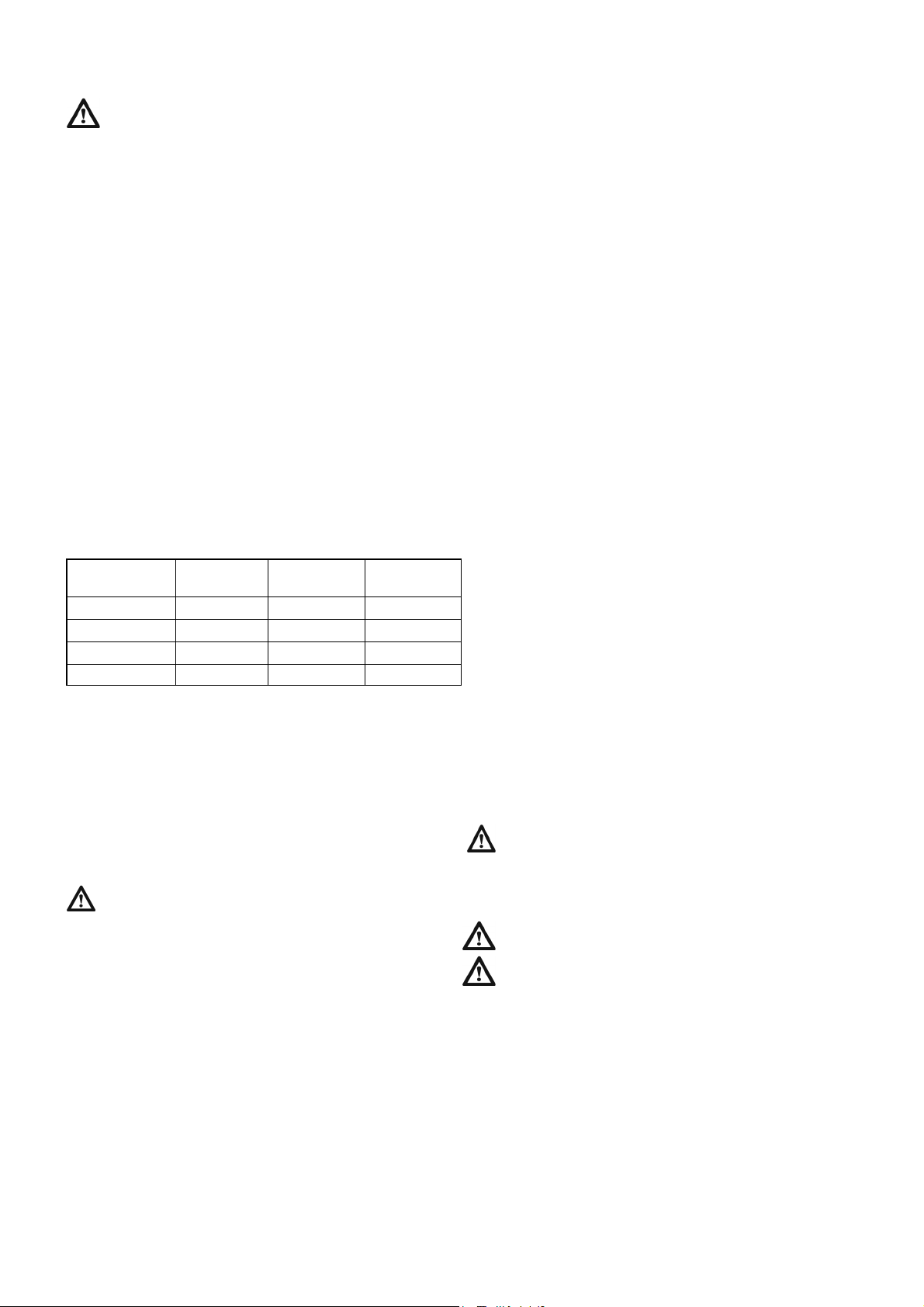
To achieve maximum throw distance, operate the
tractor engine at PTO speed. For reduced throw
distances operate the tractor at reduced engine
speeds, as per Table 1. Very slow rotor speeds may
cause blockages.
Table 1. Gearbox & PTO settings - right hand chute.
The valve block includes a flow control valve to vary the
rotational speed of the bed chain. A rotational speed of
the Bed Chain speed indicator of approximately 15 rpm
is required for the shredding of rectangular bales and
dispensing clamp silage. For round bales, indicator
speeds of up to 30 rpm may be used to improve the
feed rate.
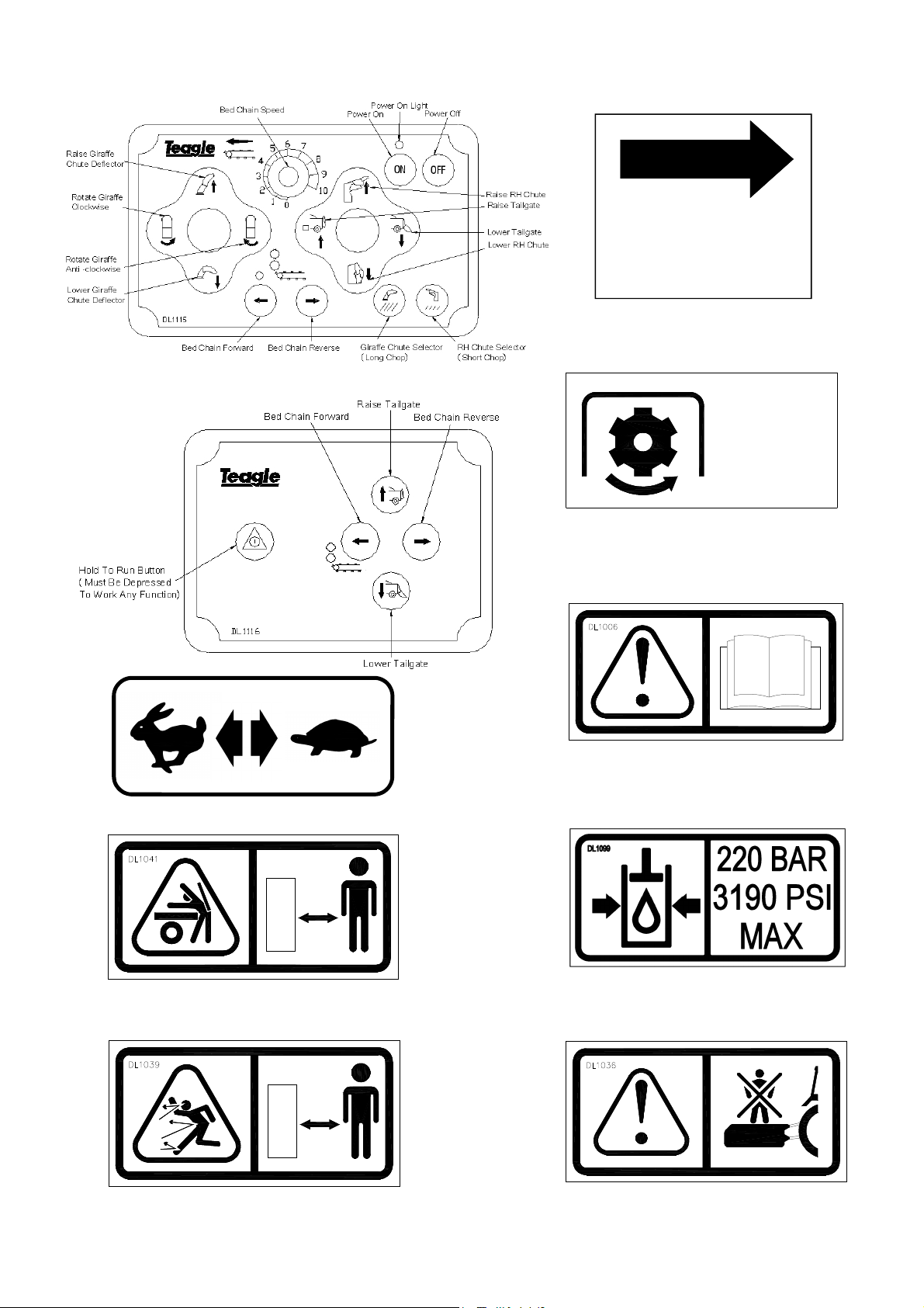
DUAL CHOP OPERATION
Dual Chop machines can not chop Silage.
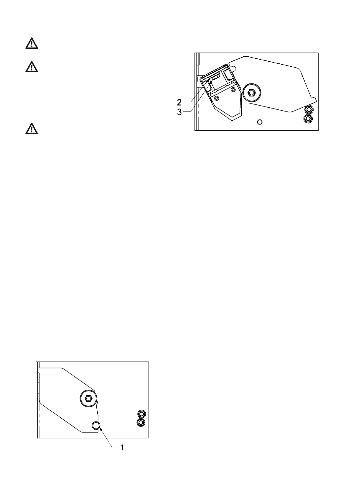
The Sliding Blade Carrier is controlled through the
hydraulic spool valve. Slots located on the front of the
machine indicate the engaged / disengaged positions of
the Sliding Blade Carrier, yellow for disengaged.
When a long chop length is desired raise the Blade
Carrier disengaging the blades.
When a fine chop length is desired lower the Blade
Carrier to engage the blades against the Crossbeater.
Before lowering the Blade Carrier, stop the Bed Chain
and wait for the material to stop flowing into the Rotor.
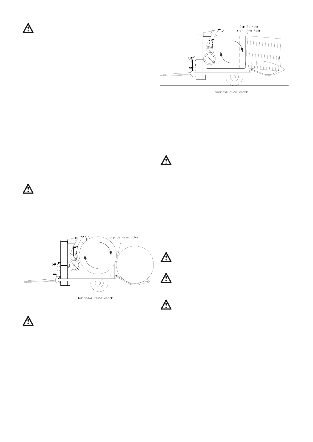
BALE RESTRAINT BEAM
The Bale Restraint Beam is factory set in the most
desirable position. If problems occur with excessive
breaking of Shear Bolts, it may be advisable to adjust
the Bale Restraint Beam backwards by one hole.
SWIVEL CHUTE
The Swivel Chute rotates through 270 degrees and can
be operated in any position.
To deliver silage close to the machine position the
Chute so that material is passed onto the Feed
Passage Slide. The position of the Slide can be
adjusted as desired.
Alternatively the material feed direction can be
controlled by the Chute. It may be necessary to rotate
the Chute fully to deliver material alongside the
drawbar.
In transport, rotate the Chute to the right hand side of
the machine aligning the indicators on the Chute and
Top Housing. Fully lower the Deflector to keep the
width and height of the machine to a minimum.
BED CHAIN OPERATION
The Bed Chain is operated by pressing forward button to
move forwards, pressing forward button to stop, and
pressing and holding reverse button to reverse. It is not
necessary to stop the Bed Chain before pressing the
reverse button as this will automatically cancel the
forward direction before engaging reverse.
COMMENCING OPERATION
LOADING THE MACHINE
The strings or net should be removed from the bale as it
is being loaded into the machine. The Tomahawk will
shred some string but some will tend to wrap around the
Crossbeater. Putting twine or netwrap through the
machine is not recommended as it will eventually be
spread on the land, polluting future crops.
Bales can be loaded into the machine in two ways, by
using a loader or by self-loading using the machine
Tailgate. If a loader is used, simply load the bale into
the Bale Chamber so that it is fully inserted. Ensure the
bale is not rammed against the crossbeater. With
square bales it is recommended that the bales are laid
on their side to aid string removal.
When loading the machine, avoid running the Bed
Chain without the rotors turning. If there is a large
amount of material still in the Bale Chamber it will be
placed into the Rotor Housing causing the Rotor to jam
at start up.
Do not stand above the machine on a stack of bales
or in a barn to load the machine manually.
When removing string or netwrap from bales never
climb into the bale chamber or onto the tailgate
behind a bale unless, the PTO has been disengaged,
the engine has been stopped, the key removed from the
ignition and the machine has come to rest.
The Tailgate is designed to load bales into the Bale
Chamber of the machine. For large rectangular bales
place the bale on the ground with one end against a
solid object. For easy removal of the strings place the
bale on its side so that the strings are not in contact with
the ground. Reverse the machine with the Tailgate
lowered until the bale slides up the Tailgate and into the
Bale Chamber. Raise the Tailgate until it is in a
horizontal position and engage the Bed Chain to move
the bale fully onto the Tailgate.
Material Distance
Spread
Gearbox
Speed
PTO Speed
Straw Maximum High 540
Straw Close High 300
Baled Silage Close Low 540
Clamp Silage Close Low 300