manuals.online logo
Brands
  1. Home
  2. •
  3. Brands
  4. •
  5. Team Losi
  6. •
  7. Toy
  8. •
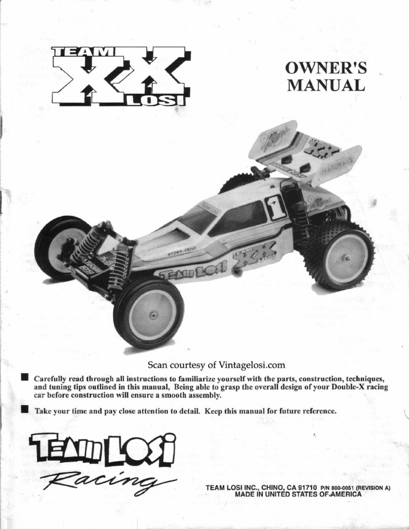
  9. Team Losi Double-XT CR Graphite Plus User manual

Team Losi Double-XT CR Graphite Plus User manual

Other Team Losi Toy manuals

Team Losi JRX-2 User manual

Team Losi

Team Losi JRX-2 User manual

Team Losi TEN-T User manual

Team Losi

Team Losi TEN-T User manual

Team Losi Sport Aftershock User manual

Team Losi

Team Losi Sport Aftershock User manual

Team Losi 8IGHT User manual

Team Losi

Team Losi 8IGHT User manual

Team Losi BK2 User manual

Team Losi

Team Losi BK2 User manual

Team Losi Mini HIGHroller User manual

Team Losi

Team Losi Mini HIGHroller User manual

Team Losi TEN-SCTE User manual

Team Losi

Team Losi TEN-SCTE User manual

Team Losi Micro-T User manual

Team Losi

Team Losi Micro-T User manual

Team Losi MINI 8IGHT-DB RTR User manual

Team Losi

Team Losi MINI 8IGHT-DB RTR User manual

Team Losi Desert Truck LOSB0102 User manual

Team Losi

Team Losi Desert Truck LOSB0102 User manual

Team Losi 810 User manual

Team Losi

Team Losi 810 User manual

Team Losi 1/10 HIGHroller User manual

Team Losi

Team Losi 1/10 HIGHroller User manual

Team Losi MINI-T User manual

Team Losi

Team Losi MINI-T User manual

Team Losi JRX-Pro User manual

Team Losi

Team Losi JRX-Pro User manual

Team Losi Double-X User manual

Team Losi

Team Losi Double-X User manual

Team Losi LOSB0103 1/10 HIGHroller RTR User manual

Team Losi

Team Losi LOSB0103 1/10 HIGHroller RTR User manual

Team Losi Mini-B Pro Roller 2WD Buggy User manual

Team Losi

Team Losi Mini-B Pro Roller 2WD Buggy User manual

Team Losi XXX-T CR User manual

Team Losi

Team Losi XXX-T CR User manual

Team Losi Mini Rockstar LOSB0209i User manual

Team Losi

Team Losi Mini Rockstar LOSB0209i User manual

Team Losi Mini 8IGHT-T User manual

Team Losi

Team Losi Mini 8IGHT-T User manual

Team Losi NIGHTCRAWLER 2.0 RTR User manual

Team Losi

Team Losi NIGHTCRAWLER 2.0 RTR User manual

Team Losi LOSB0105 User manual

Team Losi

Team Losi LOSB0105 User manual

Team Losi XXX-S Sport User manual

Team Losi

Team Losi XXX-S Sport User manual

Team Losi XXX4 User manual

Team Losi

Team Losi XXX4 User manual

Popular Toy manuals by other brands

FUTABA GY470 instruction manual

FUTABA

FUTABA GY470 instruction manual

LEGO 41116 manual

LEGO

LEGO 41116 manual

Fisher-Price ColorMe Flowerz Bouquet Maker P9692 instruction sheet

Fisher-Price

Fisher-Price ColorMe Flowerz Bouquet Maker P9692 instruction sheet

Little Tikes LITTLE HANDIWORKER 0920 Assembly instructions

Little Tikes

Little Tikes LITTLE HANDIWORKER 0920 Assembly instructions

Eduard EF-2000 Two-seater exterior Assembly instructions

Eduard

Eduard EF-2000 Two-seater exterior Assembly instructions

USA Trains EXTENDED VISION CABOOSE instructions

USA Trains

USA Trains EXTENDED VISION CABOOSE instructions

Modellbau Laffont Z1601 Assembly instructions

Modellbau Laffont

Modellbau Laffont Z1601 Assembly instructions

NOCH 12905 instruction manual

NOCH

NOCH 12905 instruction manual

Eduard Ki-61-Id quick start guide

Eduard

Eduard Ki-61-Id quick start guide

Viessmann Vollmer 45616 Mounting instruction

Viessmann

Viessmann Vollmer 45616 Mounting instruction

Vollmer 42004 Mounting instruction

Vollmer

Vollmer 42004 Mounting instruction

Phoenix Model CLASSIC-EP instruction manual

Phoenix Model

Phoenix Model CLASSIC-EP instruction manual

H-KING Sopwith Camel British WW1 Fighter instruction manual

H-KING

H-KING Sopwith Camel British WW1 Fighter instruction manual

MODSTER Predator 4x4 Crawler user manual

MODSTER

MODSTER Predator 4x4 Crawler user manual

DHK Hobby 8136 User instruction manual

DHK Hobby

DHK Hobby 8136 User instruction manual

THUNDER TIGER Raptor 50 V2 kit manual

THUNDER TIGER

THUNDER TIGER Raptor 50 V2 kit manual

Timberkits Skateboarder instructions

Timberkits

Timberkits Skateboarder instructions

Hangar 9 Funtana 125 Assembly manual

Hangar 9

Hangar 9 Funtana 125 Assembly manual

manuals.online logo
manuals.online logoBrands
  • About & Mission
  • Contact us
  • Privacy Policy
  • Terms and Conditions

Copyright 2025 Manuals.Online. All Rights Reserved.

--
OWNER•s
MANUAL
~
Carefully read
through
all
instructions
to
familiarize
yourself
wilh
the
parts,
constr
uc
tion
techniques, and
tuning
tips
outlined in
this
manual. Being able
to
grasp the overall
de~ign
of
your
Double-XT 'CR' GraphitePlus racing
truck
before
~ginning
the construction process will
ensure a smooth assembly.
,.
~
Take
your
time and pay close attention
to
detail. Keep
th
is
manual
for
future reference.
.·
Team
Losl,
Inc
.,
13848 Magnolia Ave
.,
Chino
, CA 91710
phone: (909)465-9400 •
fax:
(909)590-1496
h
tt
p;
/l
www.Teamlosi.com • feedback@Teamlosi.com
sc
an
courtesy
of
Vintagelosi.com
MADE
IN
THE
UNITED STATES
OF
AMERICA
PI
NSOG-0105
_......
Welcome
Double-XT
·cR·
Graphite
Plus
Owner
~
Thank
y
ou
for
choo
sing T
ea
m
Lo
si
an
d
the
value-packed
Do
ubl
e-X
T '
CR
'
Graph
ite
Plu
s
ki
t. As
you
probabl
y
kn
ow,
'Jearn
Los
i
has
be
en
the
pion
ee
r in
offering
feature
-
pa
ck
ed,
ra
ce-re
ad
y,
rac
e-w
inn
i
ng
RIC
car
and
t
ru
ck
kits.
Th
e
D
ouble
-XT 'CR'
Graphit
e
Plus
is
pe
rh
aps
the
bes
t
examp
le
of
this.
Titan
ium
;
carbon
fiber
/g
ra
phi
te;
precision
-
ma
c
hin
ed,
li
ghtwe
ight al
uminum;
and
space-age
coated
part
s cr
eate
a
Lru
ly
sta
te-
of
-
the
-
art
ra
ce
t
ru
ck.
Now
yo
u
can
build
a truck
like
the
ones
used
by T
ea
m L
os
i drivers
to
dominat
e
ra
cing
thr
ougho
ut
the
coun
tr
y-
winn
ing e
very
Modifi
ed Nati
ona
l
Championship
for
the
p
ast
two
years!
As always,
please
ta
ke a
mom
e
nt
to r
ead
through
the
instructions
befo
re
star
ting
the
act
ual asse
mbl
y.
Also
ch
ec
k out
•
the
tech ti
ps
for
tuning
idea
s.
Good
luck,
and
thank
you
for ch
oosi
ng
Team
Losi.
1.
INTRODUCTION
DOUBLE-XT 'CR' GRAPHITEPLUS COMPLETED KIT DIMENSIONS
Lengt
h:
15.5"
Wheelbase:
11
.4
" Front Width: 12.5" Rear Widt
h:
12.6" Heigh
t:
5.5"
All dimensions at ride height. Weight will vary depending
on
accessories.
NOTES & SYMBOLS USED
ljt.
!i!ijl
This
is
a common figure number found at the beg
in
ning
of
eac.:
h new
illu
stration throughout the manual.
0 Step I. - Each Slep throughout the entire manu
al
has a
check
box
to the le
ft
of i
i.
As
yn
u
wm
plete each step, mark the
box with a check. Ifyou need to take a break and return to build-
ing at a later time you will be
ab
le to locate the exacr step where
yo
u
left
off.
"N
OTE:Trusisa common n
ote.lt
is
used to call attention to
spec
ifi
c deta
il
s ofa certain step
in
the assemb
ly
.
&
IM
PORTANT NOTE: Even if you are familiar
wi
lh
T
ea
m Losi kits, be sure and
pa
y attention to these notes.
They
point
out
very importantdetails during the assembly process. Do
not ignore these not
es!
,......, This wrench
de
signatesa p
erf
onnance
tip. These tips
are not necess
ar
y,
but
can improve the
pe
rformance
of
your
Graphite
Plus
'CR' truck.
In
illustrations where it is important to note which
direc
ti
on parts
ar
c pointing,a helmet
li
ke this one will be incl
ud
ed
in the
illu
st
ration.
Th
e helmetw
ill
alwa
ys
face the front
of
the car.
Any reference to the right
or
left s
id
e w
ill
relate to the direc
ti
on of
the helme
L.
KIT/MANUAL ORGANIZATION
The kit is composed
of
different bags marked A through G. Each
ba
g conrains
all
of the parts necessary to complete a particular
sec
ti
on of the
Graphite
Plu
s'CR'. Some
of
these bags have s
ub
as-
sembly bags within them.
It
is
essential that you open only one
bag at a
tim
e and
follo
w the corre
ct
assembly sequence, other i
wise you may face
diffi
cu
lti
es in finding the correctpart. It is helpf
ul
to read through the instructions for an entire bag prior to b
f.'!-'111
ningasse
mb
ly.
Ke
y nu
mb
ers (
in
parenthesis) have been
a
ss
i
~
p
wd
to each partand remain the same throughout themanual. In soml
illustra
ti
on
s,
parts which havealready been installed
ar
e not
sho''
n
so that the current steps can
be
illustrated more
cl
ea
rl
y.
For your conven
ie
nce, an actual
-s
iz
e hardware
id
entifica
tion guide
is
included with each ste
p.
To check a part, hold it
against the silhouette until the correct
p:m
is identified. In som
t'
cases extra hardware has been s
up
p
li
ed
for parts that may b
l'
easy to lose.
Th
e molded parts in the
Grapltit
e
Plus
'CR' arc manufac·
lured to demanding tolerance
s.
When screws are tightened to lhe
point of being snug,
thP
p
art...,
art>
held firmly in plac
e.
For th
is
reason it
is
very
im
portant that
sc
rews not be overtightened
in
any ofthe plastic parts.
To insure that parts are not lost
dur
ing construction,
it
is
recommended that you work overa towel or marto
pr
event
pan
s
from rolling away.
IMPORTANT SAFETY NOTES
l.
Select an area for assembly thatis
awa
y from the reach
of
small children.
Th
e
pa
r
is
in
th
ekit
are
small
and
can
be
swallowed
by
clzildretz,
c
ausing
choking
and
po
ss
ib
le
inl
ema
l
injury
.
2.
The
shock fluid a
nd
greases supplied should
be
kept out
of
c
hi
ldren's reach.
Th
ey
are
not
intended
for
human
consumption.'
3.
&ercirecarewhen using
any
hand tools, sharp instrument
s,
or power tools during construction.
4.
Ca
refull
y
read
all
manufacturer's
w
arnin
gs
and
c
autions
for
any glues, chemicals, or paints that may be used for assembly and
operating purposes.

TOOLS REQUIRED
Team Losi has supplied all necessary Allen wrenches
and
a special wrenches that are
needed
for assembly
and
adjustments.
followi
ng
common
tools will also
be
r
eq
uired:
Need
le-nose p
li
ers, regularpliers,
hobby
knife, scissors
or
other
body
cutting
/t
ri
m
tools,
and
a
so
ldering ir
on
may
be
necessary for
radio
installation.
3/
16", 1/4",
and
3/8"
nut
drivers are optional.
RADIO/ELECTRICAL
A suggested radio l
ayout
is
provided
in this manual. Your high-perfotmance
RIC
center sh
ould
be
consulted regarding spec
ifio
oo
radio/electrical equipment.
HARDWARE IDENTIFICATION
When
in question, use the
hardware
identification guide in each step. For screws, the prefix
number
designates the sere"
in.>
.v>d
numbe
r of threads
per
inch (i.e., 4-
40
is
#4
screw
with
40
threads
per
inch).
The
second
number
or
fraction designates the length
the screw. For cap-
head
screws, this
number
refers to the length
of
the threaded portion
of
the screw. For flat-head screws. tht numbr.r
refers to the overall length
of
the screw. Bearings
and
bushings
are
referenced
by
the i
ns
ide
diameter
x outside
diam
et
er
!wits and
pins are
diame
ter x length. Washers arc described
by
ins
id
e diameter
or
the screw size that
will
pass through the
ms1de
d....une<n
E-clips are sized by the shaft
diameter
tha
t they attach to.
MOTORS AND GEARING
T
he
D
oub
l
e·
XT
'CR'
Graphit
e
Plus
includes
an
88
-tooth,
48
-pitch
spur
gear
.
The
overall internal drive ratio
of
the
Graphite
Pl
us
'C
R'
is 2.61: I.
The
pinion
gear
thatis used will
det
e
rmine
lhe final
dr
i
ve
rat
io.To calculate the final drive ratio,
fir
st
di,
·ide the spur
gear
size
by
the
pinion
gear
size. For
examp
le, ifyou are using a
20
-tooth
pinion
gear, you would divide 88 (
spur
gear
s
iLe
b:
10
(pinion gear
size).
88
/2
0 =4.4.
This
tells you
that
4.4is the external drive ratio. Next, multiply the internal drive ratio (
2.Ci
I
by
the external drive
ratio (in this case
4..4)
. 2.67 x 4.4 = 77.484.
Th
is
means
that by using a
20
-tooth pinion
gear
with the standard 88-tooth
sp
ur
gea
r, the
final
dt;ve
ratio is 11.481
1:
l.
Consult
your
high-performance
shop
for recommendations to suit
your
racing style
and
class.
Th
e
chan
below lists
some
of
t
he
more
common
motor
types
and
a
recommended
initial gearing for
that
motor. Ratios can
be
adjusted depending on various track
layouts, tire sizes,
and
bat
t
ery
types.
RECOMMENDED INITI
AL
GEARING
FOR
COMMON MOTORS
TYPE
OF
MOTOR PINION SPUR
24° Stock 22 88
36° Stock
21
88
1
1·
Turn Modified 16 88
12
·Turn Modified 17 88
13-Turn Modified 18 88
14
-Turn Modified 19 88
15-Turn Modified 20 88
16
-Turn Modified
21
88
17-Turn Modified 22 88
TABLE
OF
CONTENTS
1.INTRODUCTION ...................................
..
................
..
.....i 2. BAG A .........................
..
.......
..
.
..
.
..
.....................
..
...... 1
·4
Completed
Kit
Dimensions .......................................i
3.
BAG B .............................
..
........................
..
......
....
.. 5-10
Notes & Symbols .......................................................i 4.BAG C ..........
..
...
..
.
..
..
....
......
....
........
......
.........
..
.
..
.
1H4
Kit Manual Organization............................:::.......
..
....i
5.
BAG D ...........................
..
...................................... 15·22
Important Safety Notes ..............
..
...........................
..
i
6.
BAG E ..........................
..
......................
....
...........
..
23·26
Tools Required...
...
.......
...
......
..
....
..
...............
......
.......
ii
?.BAG
F............................
..
.....................
..
.....................27
Radio/Electrical
......
........................
....
....
..
...............
..
ii 8. BAG G ....
..
............................................
....
............. 28-30
HardwareIdentification .......
..
......
..
.........................
..
ii 9. Checklist
Be
foreYour First Run ...................................
31
Recommended Gearing ..
...
...............
....
................... ii 10.Tips From the Team .............................................
..
31
·33
11
.Spare Parts List ......................................
..
....
....
..... 34·36
Team
Losi
is
co
nHmulll
y c
han
g
ing
and
improvin
g
d
es
ig1~1;
th
e
refor
e,
th
e
acwal
part
may
appear
slightly
different
than
the
illustrated
pa
r
t.
Jllustmti
ons
of
parts
and
assemblies
may
be
slight/)'
distorted
to
enhanc
e
pertinent
details
.
ii
scan courtesy of Vintagelosi.com
'
BAGA
'i[.!!ii¥1
0 Step
J.
Attach the f
ront
bu
lkhead (I) to the main chass
is
(2)
by aligning lhe bottom hinge holes
on
the bulkhead (I) and the
main chassis (2}.
Onc
e the holes
are
aligned, carefu
ll
y tap the
118"
lower bulkhead hinge pin (3}through
the
bulkh
ead
(I}and
the
ch
assis
(
~
)
until the hinge pin {3)
is
centered
in
the chassis (2).
*NOT
E:
Use
the
7/8
"hinge
pin with
the
lar
ge
groove
in
th
e
cen
ter
.
The
lo
wer
hinge
pin fit
is
VERY TIGHT! Be
sure
that
th
e
hol
es
ar
e
aligned
before
tapping
th
epin
th
roug
h
the
p
arts.
0 Step2. Secure the pin (3)
by
threadinga 2-
.56
x 51
16"
button-
head screw
(·
~
)
into the sma
JI
ho
le
Oocated
at
the rear)
in
the
top
of
the front bulkhead (I).
Thr
ea
d the screw
(4)
all the way in.
0 Step 3. Attach the front chassis stiffener
(5)
to the
fT
ont bulk-
head (I) b) aligni
ng
the holes in the sti!Jener (5) with the holes
in
the
tO
p hinge of the bulkhead (1). Secure the two parts by inseit-
ing the
II
H"
upper
bulkhead hinge pin (6}lhrough both the bul
k-
head (I) and stiffener (
.5
).
'NOTE:
Use
the
shortest
718
"
!ting
e pin witlwut a
groove
in
th
e
c
enter
.
The
hinge
pinfit
is
tight!
Lightly
tap
th
e
hinge
pin
through
both
parts untilit
is
centered.
0 Step 4. Center the hinge pin (6) and attach an
l/8"
£-
cl
ip (7)
to
each end
of
the hinge pin (6).
~
When removing the front
l>u
lkh
ea
d for any reason,
the 2-56 x 5/ 16" button-head screw
mu
st be co
mp
lelely removed
before removing the lower hinge pin.
1
it.li!i¥1
0
11
111111:
lllllil,
llll
tUII'IIIIII
[:D
® @
0 Step 5. Insert a 1/4" ball stud (8) into each of the inside holes
on the bottom
of
the shock tower (9). Mount the ball studs
(
~
)
from
th
e rear as s
how
n.
0 Step
6.
Insert a 4-40 x
718"
cap-h
ead
screw (
10
) from the
rear, through the inside hole in on the top
of
the shock to
we
r
(9
)
on each side.
Threa
d a top shock
mount
bushing (
11
) onto each
of
the two screws (
10
) and tighten.
,6
IMPORTANT
NOTE:
Remove all flashing from the
bottom
of
the front shock tower. This
wi
ll
ensure
prop
er
fit
of the
fro
nt
shock t
ower
to the front bulkhead.
1
D
®
5
(fum m
@
\ \
Figure
1
p
~
Figur
e 2
til
®
scan
courtesy ofVintagelosi.com
@"?)
cv
BAG A
(Continued)
'i'·!i"i'
@
0 Step
7.
Attach
th
e front shock tower (9) to the front s
id
e
of
the front bulkhead (I) with f
our
4·40x 3/8"cap-headscrews (
12
).
0 Step
8.
Attach the front body
mount
(
13
) to t
he
front side
of
the front shock tower (9) with two 4-40 x
3/l:!"
cap
-head screws
(12
) as shown.
@
0 Step 9. Insert a
fr
ont axle (
14
) into each
of
the front
sp
indles
[left (1
5),
ri
ght (1
6)
) as shown.
Th
e hole
in
the
ax
le (14) should
line
up
with the hole
in
the spindle (
15
),
(1
6).
0 Step
10.
Place four ball stud washers (
18
) over the
end
of
a
kingpin/ball stud (
1
9)
.Slide the washers (
18
) all the way against
the base
of
the ball stud on the kingpin/ball stud (
19
).
0 Step
11.
Attach
the
right
sp
indle (
16
) to
one
of
the spindle
carriers
(
17
)
by
a
li
gning
the
holes
in
each
and
inserting
a
the kingpin/ba
ll
stud (1
9),
with washers attached, through the
spindle carrier (
17
), spindl
t:
(16
),
and axle (
14
). Secure the kin
g-
pin
/ha
ll
stud (19) with a 3/
32"
E·clip (20)
at
the bottom
of
the
shaft.
&
IMPOR
TANT NOTE:
Th
ere are two siz;s
of'E'
clips
in this assembly bag. Be sure to usc the small E-clips on the
3/ 32" pins.
0 Step 1
2.
Check to see that the spindle (16) rotates easily in
the spindle carrier (17
).
If
the spindle doesn't rotate easily,
mo
ve
the kingpin
/ba
ll
stud
up
slightly so that there
is
a small s
pa
ce
between the washers (
18
) and the spindle carrier (
17
).
Once
the
spindle (1
6)
rotates easily,
thr
ea
d a 5-40 setscrew (21) into the
back side of
th
e axle (14) and tighen.
0 Step 13. R
epea
t Steps J0-12 for the left
spi
ndle (
IS
) and the
second spindle carr
ie
r (
17
).
Figure
3
16
Figure
4
14
2
19
..
BAG
A
(Continued)
@ @
CJ
Step
14.
Insert a
4-tJO
mini locknut (22) into the hex area in
the bottom
of
ea
ch spindle (15), (
16
).
Thr
ea
d a 3/16" ball stud
(23) in from the top and tighten.
&
IMP
ORTANT
NOTE
: Do
not
overtighten the ball
studs!
iij!ijil#j
10
Figure
5
Dl
CJ
Step I
S.
Attach the right spindle and
carr
ier assembly to the right front suspension arm (
25)
as shown. Line up the hol
es
in
the
sp
indle carrier (
17
) with the holes in the front arm (25
),
inse
rt
a
3/32"
x
1.
050" hinge pin
(26)
and
attach a 3/32" E-clip
(2
0)
to both
sides
of
the hinge pin (26).
& IM
PORT
ANT
NO
TE:
There
are
two sizes of £-clips in this
a~sembly
bag
. Be sure to use the small E-clips on the
3/32" pins.
CJ
Step
16.
Attach the arm (25) to the right side
of
the front bulkhead
(I)
by inserting the 1/
8"
inner front hinge pin
(27),
from the
front, through the arm (25) and bulkhead (1).
CJ
Step
17.
Inserr a 1/ 8" £-clip (7)
in
lhe r
ea
r groove.
of
the hinge pin (
27
).
CJ
Step
IR.
R
epea
t Steps
15
-
17
for the left spindle
and
carrier assembly and left suspension arm (24).
CJ
Step
19.
Slide the front hinge pin
bra
ce (28) over the front
of
bo
th hinge pins (27
).
Be
su
re that the brace
(2
8)
is
installed correctly
so that
theE
-clipgrooves
in
both
hing
e pins (27) are exposed. Secure the brace by attachinga
L/8"
£-clip (7) to the front ofeach hinge
pin (27).
27
25
I
Figure
6
3
BAG A
(Continued)
Ut.!i!l¥
1
0 Step 20.
Thr
ead a plastic rod
end
(29) onto each
end
of
a 2-3/4" turnbuckle
(3
0). Tighten both rod ends (29) equally until the rod
is
Lhe
same
length as the rod in figure 7
A.
Make two
of
these
camber
link assemblies.
30
..
~
Figure
7
cr===
~~
CI==~u~==
~r-
~-~d~~
Figure
7A
0 Step
21.
Place a "foam thing" {
31
) over the ball
on
each
of
the kingpin/ball
st1.
1d
s (
19
)
in
th
e spindle carriers (1
7}
and the ball studs
(8)
in
the shock tower{9}. Next, attach
one
side
of
a camber link assembly to the
ba
ll
stud
(8)
on the right side
of
the shock tower
(9).
Attach the
other
side
of
the camber link assembly to the kingpin/ball stud
in
the spindle carrier (1
7).
0 Step 22. Attach the second camber link assembly to the left
si
de
of
the truck.
~
Try to m'ount all
of
the camber links so that the threads adjust the same
dir
ection. This makes it much easier to make
adjustments later. I
31
Figure
8
4
"
BAG
B
'U
·
!i"¥'
~
llllllmJ10
~
@
® @ @
0 tep
l.
Place theservo saver bottom
(3
2)overthe servo saver
po
st (
:-13
) and slide the servo saver bottom
aU
the way down. Be
sure that the hex
in
the servo saver
po
st (33)
is
inserted into the
hex in the servo saver bottom (32).
0 Step 2. Slide
lht!
servo saver top (34) down
over
the servo
saver post (
33
)so that itrests against the servosaver bottom (32).
The
arm on the servo saver top (34} and the arm
on
the servo
saver bottom
(32)
should point
in
opposite directions.
0 Step 3. Slide the servo saver spring
(35)
over the servo saver
post (33)
and
push it into the recessed area
of
the servo saver top
{
34
). Install the servo saver spring cap (36) and thread the
6--W
locknut
(3
7)
onto the threads of the servo saver post (33).
0 Step 4. Tighten the 6-
40
locknut
(37)
a
ll
the way down and
then loosen
it
two
full
turns (e.g.
360
ox 2).This
is
a good starting
point for the adjustment. Once assembly
is
complete, ifyou wish,
the servo saver can be adjusted tighter
or
looser.
® @
0 Step 5. Insert a 4-
40
mini locknut (22) into the outside hex
area
in
the servo saver bottom (32)
and
steering idlerarm (38) as
show
n.
Pl
ace two ball stud washers
(1
8)over each
of
the two
114"
baJI
studs (8).
Th
read a 1/4"
baJI
stud (8) through the outside hole
in each arm,
int
o the nuts (22), and tighten. Insert a
-1-
-
40
mini
locknut(22) into the hex area in the servo saver top (
34
).Thread
a
3/
1
6"
ba
ll
stud
(23
) through the hole in the arm, into the nut
(22), a
nd
tighten.
0
Step
6. I
nsert
a 4-
40
mini
locknut
(22)
into
the
hex
areas in the
rear
of
the servo saver bottom (32)
and
the steering
idler
arm
(38) as shown.
Thr
ead a 3/16"
ba
ll
stud (23) through
the arms, into each nut (22), and lighten.
1
it.l'lli
11
I
Bnlll
0
[IIIII"'"
1111111111111~1111
bt:
mJlJJlJDl!JID
0 Step
7.
Thr
ead a plastic rod
end
(
2!:1
) onto each e
nd
of
a
2-3/8" turnbuc
kl
e (
39
). Tighten both rod ends (29) equally until
the completed lie rod assembly
is
the same length as the one in
Figure II
A.
Make two
of
these
li
e rod assemblies.
0 Step 8.
Thread
a short plastic rod end (
40
) onto each end
of
the 1-
118
'' turnbuc
kl
e (
41
). Tighten both rod ends (
40
) equally
un
ti
l the
comp
leted
drag
link
is
the same length as the
one
in
Figure Il
A.
5
@
@
~~
34·
"®
35
32
Figure
9
Figure 10
~
~
Figure11
~~
@ @
Figure
77A
BAG B
(Continued)
1
i'
·
!l
11
ifJ
D Step 9.
Snap
one
end
of
t
he
short
drag
link
to
the rear ball
stud (23)
on
the
servo
saver
bottom
(3
2).
Snap
the
other
end
to
the rear ball stud (
23
)
on
the steering idler
arm
(
38
).
"NOTE:
Be
sure
to
snap
the
rod
onto
the
correct
ball
studs
as
shown!
I
a[.!!'
ii
fl
10
01
@
0 Step
10.
Inserta
3/32"
x 3/
16"
bearing (
42
)into the two large
holes
in
the
bottom
of
the steering brace (
43
). Insert t
he
other
two bearings {42) into the two holes in the
ma
in chassis (2).
0 Step
ll.
Inser
t a
3/32"
x .930" hinge pin (
44
) through the
hole
in
the steering idler
arm
(3
8)
and
position it as shown in
Figure 13A. Place the servo saver assembly
and
the steeringidler
arm
(38) into
the
bearings (
42
) in
the
chassis (2) so
that
the
installed
drag
link is in
th
e front.
0 Step
12.
Place the steering brace
(4
3)
on
top
of
the servo
saver
assembly
and
steering idler
arm
(38)
being
sure that
th
e
bearings (42) slide
over
the pins.
0 Step
13.
Attach the stee
ring
brace to the chassis (2) usingtwo
4-
40
x
3/8"
cap-head screws (
12
).
&
IMPOR
TANT NOTE: Tighten the two 4-40 screws
all the way
and
then
back
them
off 1
/8
of
a rurn. This
vvi
ll
keep
the posts
on
the chassis from "taking a ser" ifthey should twist at
all.
Figure
72
Figure
73A
6
32
Figure
73
•
BAG
B
(Continued)
0 Step 14. Snap one end
of
a completed tie rod
a<osembly
to
the
ball stud (8) in
th
e idler arm (
38
). Snap the other
end
to the ball stud
(23}in the right spindle (16). Attach the
other
tie rod assembly to the ball studs
in
the servo saver assembly and the l
ef
t spindle (
15
).
>-=>
On
ce
again, assure that all turnbuc
kl
es
ar
e
mou
nted w
it
h the thr
ea
ds
in
the same dil·ection f
or
easi
er
adjustment later!
16
1
it.l'liifj
~N
OTE:
If
you
do
not
ha
ve
your
servo
at
this
time,
skip
to
Bag
C
and
con
tinue
assembly.
It
is
recomm
e
nded
that
th
e
:;ervo
be
inrtalled
at
th
is
t
ime
since
muc
h
of
the
front
end ofthe
truck
is
built
around
the
servo
and
minor
disass
e
mbl
y willbe
requ
ir
ed
to
install it
later.
&
IMP
OR
TANT
NO
TE
:
If
the
se
rvo
mo
unting
instructions are not
fo
ll
owed carefully, your servo
may
be d
am
-
aged!
0 Step I
S.
Using a flle
or
a
Dr
emel tool,
trim
the two lower
e
ar
s o
ff
of yo
ur
servo
(not
included)
as shown
in
Figure
15.
Be
very
e<tr
eful to Lrim
th
e
conect
ears! Ifthe wrong
ea
rs arc trimmed,
your
servo will not be able to be mounted unless the servo case is
replaced.
6
IMP
ORTANT NO
TE:
It
is
not reco
mmended
thatyou
use cutters
or
a h
obby
knife to re
mov
e t
he
servo ears. Some cases
are made
of
very brittle
mat
er
ial
and
dama
ge to your servo case
ma
y resul
t.
F
igure
74
Figure
75
7