INTRODUCTION
(C
ont.)
TOOL
S
REQUIR
ED
Team Losi has supplied all allen wrenches
and a special wrench that
is
needed foras-
sembly and adjustments. The following com-
mon
tools will also be required:
#2
Phillips
screw driver, small flatblade screwdriver,
needle nose pliers, regular pliers, scissors
or
other body cutting/trimming tool. 3/16'', 1/4",
and 3/8"
nut
driversare optional.
RADIO/
ELECT
RICAL
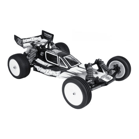
The JRX-PRO is an out
of
the box high perfor-
mance race car. It is for
this
reason that we
have not included specific instructions on
radio and electrical equipment installation.
We
have left
this
subject
to
the personal
preference
of
the owner/racer.
A suggested layout is provided In
this
manual.
If
you have any further
quest
ions,
your high performance R/C center will be
able
to
answer any
of
your questions.
HARDWARE IDENTIFICATION
When
in
question, use
the
hardware iden-
tification guide
in
Appendix
A.
For screws,
the prefix numberdesignates the screw
size and numberthreads per Inch e.g., 4-40
is a
#4
screw with 40 threads per inch. The
fraction following designates length
of
thread
or
overall
if
flathead type. Bearings
are referenced
by
inside diameter X outside
diameter. Shafts and pins are diameterX
length. Washers are described
by
inside
diameter. E-clips are sized by the shaft
diameter of attachment.
TABLE OF CONTENTS
1.1NTRODUCTION 6.SHOCKS • BAG E
Important Safety Notes.................................. i ShockAssembly ............................................ 16
Tools Required.........................................
..
.... ii Illustration -Shock Assembly.....................
...
17
Hardware.
...
....................................................ii ShockAttachment......................................... 18
Radio/Electrical ......................................
......
..ii 7.WHEELS &
TIRES·
BAG F
Table
of
Contents............................
...
.......
..
.
..
ii Assembly and Attachment ............................ 19
2.CHASSIS • BAG A 8.FINAL ASSEMBLY
Chassis Assembly.......................................... 1-3 Motor. Antenna.
Body
Painting
...
....
.
..
...
..
..... 20
Illustration -Chassis....................................... 4 Body, Gear Cover. Wing ................................
21
3.GEARBOX I DIFFERENTIAL BAG B Wing Buttons
......
....
..
....
.
....
..
.....
....
.
..
....
.
..
..
.... 22
Part 1 Differential Assembly........................... 5 9.ELECTRICAL/ELECTRONIC
Part 2 Gearbox Assembly...........................
...
6 Suggested Layout..........................................
23
Illustration -Exploded Gearbox...................
..
7 10.TUNING TIPS
............................
........
....
24-26
Part 2 Gearbox Assembly (cont.)..................8
11
.TOE IN I TOE OUT & CAMBER
...
27
4.REAR SUSPENSION -BAG C 12.APPENDIX A
Rear Suspension............................................9-11
Illustration -Rear Suspension........................ 12
S.FRONT SUSPENSION • BAG D
Front Suspension........................................... 13 -14
Hardware
10
Guide
..
...................................... 28-29
13.SPARE PARTS LIST
..........................
30-32
14
.MAINTENANCE SCHEDULE .
......
33
Illustration -Front Suspension ...................... 15
ii
