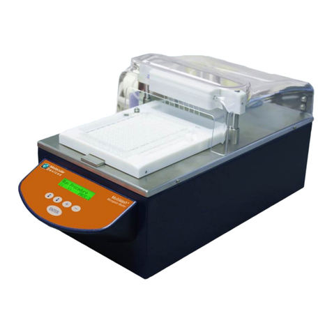
tecan Columbus Washer User manual

Technical Manual for
Columbus Washer
Document Part No.: 30000294
2006-02
Document Revision No.: 1.7
Firmware Level: 4.xx

2 Technical Manual for Columbus Washer No. 30000294 Rev. No. 1.7 2006-02
TECAN Affiliates and Service Centers
Austria
Tecan Austria GmbH
Untersbergstrasse 1a
A-5082 Grödig/Salzburg
Austria
T +43 6246 8933 256
F +43 6246 72 770
Austria
Tecan Sales International GmbH
Untersbergstrasse 1a
A-5082 Grödig/Salzburg
Austria
Tel.: +43 6246 8933
Fax: +43 6246 72 770
Asia
Tecan Asia Pte Ltd.
80 Marine Parade
#10-09 Parkway Parade
Singapore 449269
Singapore
T +65 6444 1886
F +65 6444 1836
tecan@tecan.com.sg
Belgium
Tecan Benelux bvba
Vaartdijk 55
B-2800 Mechelen
Belgium
T +32 15 42 13 19
F +32 15 42 16 12
tecan-be@tecan.com
China
Tecan Group Ltd, Beijing
Representative Office
Room 2502, Building A
Jianwai SOHO
No. 39 Dongsanhuan Zhong Rd.
100022 Beijing
China
T +86 10 5869 5936
F +86 10 5869 5935
France
Tecan France SAS
26 avenue Tony Garnier
F-69007 Lyon
France
T +33 820 88 77 36
F +33 472 76 04 99
Germany
Tecan Deutschland GmbH
Theodor-Storm-Strasse 17
D-74564 Crailsheim
Germany
T +49 1805 8322 633 or
T +49 1805 TECANDE
F +49 7951 9417 92
Italy
Tecan Italia S.r.l.
Via F.lli Cervi
Palazzo Bernini
Centro Direzionale Milano 2
I-20090 Segrate (Mi)
Italy
T +39 02 215 21 28
F +39 02 215 97 441
Japan
Tecan Japan Co., Ltd.
Kawasaki Tech Center
580-16, Horikawa-cho,
Saiwai-ku
Kawasaki, Kanagawa 212-0013
Japan
T +81 44 556 7311 (Kawasaki)
F +81 44 556 7312 (Kawasaki)
T +81 66 305 8511 (Osaka)
Netherlands
Tecan Benelux bvba
Industrieweg 30
NL-4283 GZ Giessen
Netherlands
T +31 183 44 81 74
F +31 183 44 80 67
tecan-nl@tecan.com
Scandinavia
Tecan Nordic AB
Taljegårdsgatan 1
SE-431 53 Mölndal
Sweden
T +46 317 54 40 00
F +46 317 54 40 10
Spain (Barcelona)
Tecan Ibérica
Sabino de Arana 32
E-08028 Barcelona
Spain
T +34 93 490 0174
T +34 93 409 1237 (Helpdesk)
F +34 93 411 2407
helpdesk-sp@tecan.com
Spain (Madrid)
Tecan Ibérica
Gobelas 17 bjo. Izq. Urb. La Florida
E-28023 Madrid
Spain
T +34 91 151 7107
T +34 93 409 1237 (Helpdesk)
F +34 91 151 7120
helpdesk-sp@tecan.com
Portugal
Tecan Ibérica
Quinta da Fonte Edificio Pedro I
P-2780-730 Paço D'Arcos
Portugal
T +35 21 000 8216
Switzerland
Tecan Schweiz AG
Seestrasse 103
CH-8708 Männedorf
Switzerland
T +41 44 922 82 82
F +41 44 922 84 84
helpdesk-ch@tecan.com
United Kingdom
Tecan UK
Theale Court
11-13 High Street
Theale
UK-Reading RG7 5AH
United Kingdom
T +44 118 930 0300
F +44 118 930 5671
USA
Tecan US
4022 Stirrup Creek Road
Suite 310
Durham, NC 27703
USA
T +1 919 361 5200
F +1 919 361 5201
Toll Free US:
T +1 800 TECAN US or
T +1 800 832 2687
USA
Tecan Systems Inc.
2450 Zanker Road
San Jose, CA 95131
USA
T +1 408 953 3100
F +1 408 953 3101
Toll Free US/Canada:
T +1 866 798 3226

2006-02 Technical Manual for Columbus Washer No. 30000294 Rev. No. 1.7 3
WARNING
CAREFULLY READ AND FOLLOW THE INSTRUCTIONS
PROVIDED IN THIS MANUAL BEFORE OPERATING THE
INSTRUMENT.
Notice
Every effort has been made to avoid errors in text and diagrams, however, Tecan
Austria GmbH assumes no responsibility for any errors which may appear in this
publication.
It is the policy of Tecan Austria GmbH to improve products as new techniques
and components become available. Tecan Austria GmbH therefore reserves
the right to change specifications at any time.
We would appreciate any comments on this publication.
Tecan Austria GmbH
Untersbergstraße 1A
A-5082 Grödig/Salzburg
AUSTRIA / EUROPE
Telephone: 0043 (0)6246/8933
FAX: 0043 (0) 6246/72770
www.tecan.com
Copyright Information
The contents of this manual are the property of Tecan Austria GmbH and are not
to be copied, reproduced or transferred to another person or persons without our
prior written permission.
Copyright ©Tecan Austria GmbH
All rights reserved.
Printed in Austria.
Declaration for EU Certificate
See the back of this manual.
About this Manual
This technical manual describes the servicing of the Columbus Washer, designed
to wash microplates. It is intended only for service personnel.
This manual instructs how to:
•Install the instrument
•Operate the instrument
•Programming the wash procedure
•Definition on the wash parameters
•Cleaning and maintenance procedures

4 Technical Manual for Columbus Washer No. 30000294 Rev. No. 1.7 2006-02
Warnings, Cautions and Notes
There are three types of informational notices used in this manual. These notices
highlight important information or warn the user of a potentially dangerous
situation. The following notices are:
Note
Gives helpful information.
Caution
Indicates a possibility of instrument damage or data loss if instructions are
not followed.
WARNING
INDICATES THE POSSIBILITY OF SEVERE PERSONAL INJURY, LOSS OF
LIFE OR EQUIPMENT DAMAGE IF THE INSTRUCTIONS ARE NOT
FOLLOWED.

2006-02 Technical Manual for Columbus Washer No. 30000294 Rev. No. 1.7 5
Table of Contents
1. General
1.1 Overview......................................................................................... 1-1
1.2 Instrument Description ................................................................. 1-2
1.2.1 Rear Panel Connections.................................................................. 1-2
1.2.2 Connection Diagram for Columbus (1 Liquid Channel)*.................. 1-4
1.2.3 Connection Diagram for Columbus (4 Liquid Channels)*................ 1-5
1.2.4 Keyboard and Display Unit.............................................................. 1-6
1.3 Interconnection Diagram .............................................................. 1-7
2. Installation Procedure
2.1 Unpacking and Inspection............................................................ 2-1
2.2 Unpacking Procedure ................................................................... 2-2
2.3 Power Requirements..................................................................... 2-2
2.4 Installation Procedure................................................................... 2-3
2.4.1 Installing the Instrument ..................................................................2-3
2.4.2 Connecting the Waste Tubing......................................................... 2-3
2.4.3 Connecting the Solution Tubes ....................................................... 2-4
2.4.4 Fitting and Connecting the Liquid Sensors (Optional)..................... 2-5
2.4.5 Connecting the Barcode Reader (Optional)..................................... 2-6
2.4.6 Connecting the Printer (Optional).................................................... 2-6
2.4.7 Power Connections ......................................................................... 2-6
3. Firmware and Software Description
3.1 Instrument Software Features...................................................... 3-1
3.2 Onboard Software Menus............................................................. 3-2
3.2.1 Run.................................................................................................. 3-2
3.2.2 Prime ............................................................................................... 3-2
3.2.3 Rinse ............................................................................................... 3-3
3.2.4 Program........................................................................................... 3-6
3.2.5 Clear................................................................................................ 3-6
3.2.6 Show................................................................................................ 3-6
3.2.7 Adjust............................................................................................... 3-7
3.2.8 Service Menu................................................................................. 3-24
3.3 External Software ........................................................................ 3-61
3.3.1 Columbus Computer Software ...................................................... 3-61
3.3.2 Firmware Update........................................................................... 3-61
3.4 Serial Interface............................................................................. 3-62
3.4.1 Hardware Specifications................................................................ 3-62
3.4.2 Contents ........................................................................................ 3-65
3.4.3 A. Protocol..................................................................................... 3-67
3.4.4 Sequence Number......................................................................... 3-68
3.4.5 B. Commands - Overview.............................................................. 3-69
3.4.6 Commands - Description............................................................... 3-71

6 Technical Manual for Columbus Washer No. 30000294 Rev. No. 1.7 2006-02
3.4.7 D. Examples for Remote Control - Command Sequences.............3-88
3.5 Description of Error Messages...................................................3-95
4. Removing and Replacing the Instruments Cover
4.1 Removal of Instruments Top Cover..............................................4-1
4.2 Replacing the Instruments Top Cover .........................................4-3
5. Liquid System
5.1 Introduction ....................................................................................5-1
5.1.1 Liquid System Diagram....................................................................5-2
5.1.2 Dispensing System Description........................................................5-3
5.2 Replacement Procedure................................................................5-4
5.2.1 Replacing the Dispensing Pump......................................................5-4
5.2.2 Replacing the Solution Solenoid Valves (Instruments with Pinch
Valves) .............................................................................................5-6
5.2.3 Replacing the Solution Solenoid Valves...........................................5-7
5.2.4 Replacing the Dispense Solenoid Valve ..........................................5-8
5.2.5 Replacing the Aspirating Pump........................................................5-9
5.2.6 Replacing the Aerosol Pump..........................................................5-10
6. Mechanical System
6.1 Manifold Arm Movement System..................................................6-1
6.1.1 Description of Manifold Arm Movement Parts..................................6-2
6.1.2 Adjusting the Manifold......................................................................6-2
6.2 Plate Transport System.................................................................6-3
6.2.1 Plate Support ...................................................................................6-4
6.2.2 Leveling the Plate Support...............................................................6-5
6.2.3 Microplate Positioning System.........................................................6-7
6.3 Replacement Procedure................................................................6-8
6.3.1 Replacing the Manifold Arm Error Sensor........................................6-8
6.3.2 Replacing the Motor.........................................................................6-9
6.3.3 Replacing the Top Position Optical Switch.....................................6-10
6.3.4 Replacing the Plate Support Home Position Optical Switch ..........6-11
7. Electronic System
7.1 Introduction ....................................................................................7-1
7.2 Interconnection Diagram...............................................................7-2
7.3 Main Board......................................................................................7-3
7.3.1 Replacing the Main Board................................................................7-4
7.3.2 Replacing the Battery.......................................................................7-5
7.4 Power Supply Board ......................................................................7-6
7.4.1 Replacing the Power Supply Board..................................................7-7
7.5 Keyboard and Display Unit............................................................7-8
7.5.1 Replacing the Keyboard or Display Unit...........................................7-9
7.6 Manifold Detect Board.................................................................7-11
7.6.1 Replacing the Manifold Detect Board.............................................7-11

2006-02 Technical Manual for Columbus Washer No. 30000294 Rev. No. 1.7 7
7.7 Fill Verification Board ................................................................. 7-13
7.7.1 Replacing the Fill Verification Board.............................................. 7-13
7.8 Optical Switches.......................................................................... 7-15
8. Serial Interface
8.1 Hardware Specifications............................................................... 8-1
8.1.1 Pin Designation ............................................................................... 8-1
8.1.2 RS-232-C Interface Lines................................................................ 8-2
8.1.3 Synchronization and Data Format................................................... 8-3
8.1.4 Daisy Chaining Instruments............................................................. 8-3
9. Description of Options
9.1 Instrument Options ....................................................................... 9-1
9.2 Liquid Detection Option................................................................ 9-3
9.3 Barcode Reader Option ................................................................ 9-4
9.4 Printer Option ................................................................................ 9-5
9.5 Manifold Detection Option............................................................ 9-6
9.6 Fill Verification Option .................................................................. 9-8
9.7 Aerosol Pump Option.................................................................... 9-8
9.8 Activating the Options .................................................................. 9-8
10. Maintenance
10.1 Cleaning Maintenance................................................................. 10-1
10.1.1 Cleaning the Manifold.................................................................... 10-1
10.1.2 Exchanging the Manifold ............................................................... 10-3
10.1.3 Exchanging the Plate Support....................................................... 10-5
10.1.4 Instrument Disinfection.................................................................. 10-6
10.2 Preventive Maintenance Plan..................................................... 10-8
10.2.1 Daily............................................................................................... 10-8
10.2.2 Weekly........................................................................................... 10-8
10.2.3 Every Six Months........................................................................... 10-8
10.2.4 Yearly (Service Technician Required)........................................... 10-8
10.3 Service Tools ............................................................................... 10-9
10.3.1 Adjustment Plate (Reference Plate).............................................. 10-9
10.4 Electrostatic Discharge Information........................................ 10-10
10.4.1 Generating Static......................................................................... 10-10
10.4.2 Preventing Electrostatic Damage to Equipment.......................... 10-11
10.4.3 Personal Grounding Methods...................................................... 10-11
11. Trouble Shooting
11.1 Introduction.................................................................................. 11-1
12. Instrument Specifications
12.1 Introduction.................................................................................. 12-1
Index


1. General
2006-02 Technical Manual for Columbus Washer No. 30000294 Rev. No. 1.7 1-1
1. General
1.1 Overview
This is a technical manual for servicing the Columbus Washer.
The instrument is a microprocessor controlled washer, designed to wash
microplates.
The instrument can be fitted with either an 8, 12 or 16 way manifold or a 384 Well
Manifold.
The manifolds are fitted with one aspirating and one dispensing needle per well.
The instrument can store up to nine software user-defined plate types including
dispensing and aspirating positions as well as the shape of the plate.
The dispensing speed can be selected from five set speeds and dropwise.
These features allow the instrument to be used for all washing applications
including Cell Washing applications.
The instrument should only be opened by authorized personnel. Before the
instrument is opened the mains power cable must be disconnected from
the mains power socket.
Ensure that the instrument has been disinfected before it is serviced.

1. General
1-2 Technical Manual for Columbus Washer No. 30000294 Rev. No. 1.7 2006-02
1.2 Instrument Description
The diagram below shows the main components of the instrument:
Keyboard and
Display Unit
Manifold Arm
Manifold
Waste Sink
Plate Support
Guide Bar
POWER
Power ON LED
1.2.1 Rear Panel Connections
The instrument has the following connections on the back panel.
ON/OFF
Switch
Fuse
Compartment
Mains Power
Socket
Printer Connecto
r
or
Serial RS 232 fo
r
Remote Control
Hand held
Barcode
Reader
Bottle Holder with
Liquid Sensor for
each bottle
Waste
Tubing
(
red
)
A
erosol
Tubing
(
option
)
Inlets for channels 1 - 4

1. General
2006-02 Technical Manual for Columbus Washer No. 30000294 Rev. No. 1.7 1-3
(Instrument with Pinch Valves)
ON/OFF
Switch
Fuse
C
ompartment
Mains Power
Socket
Printer Connector
or
Serial RS 232 for
Remote Control
Hand held
Barcode
Reader
Bottle Holder with
Liquid Sensor for
each bottle
Waste
Tubing
(red)
A
erosol
Tubing
(yellow)
Channel 1
Inlet Channel 2
Inlet Channel 3
Inlet Channel 4
Inlet
Prime
valve
All connected devices must be proved and listed with regulations
EN 60950, UL 1950 or CSA C22.2 No. 950 for Data Processing Devices

1. General
1-4 Technical Manual for Columbus Washer No. 30000294 Rev. No. 1.7 2006-02
1.2.2 Connection Diagram for Columbus (1 Liquid Channel)*
Printer
(
o
p
tion
)
Hand held
Barcode
Reader (option)
or
Com
p
uter for
Remote Control
Marked
red
Prime
valve
Bottle Holder with li
q
uid
sensor for each bottle
grey red
g
reen Waste
Bottle
Wash
Li
q
uid
Inlet
filter
Rinse
solution
Marked
g
reen
*Some of the instruments may include the prime valve.

1. General
2006-02 Technical Manual for Columbus Washer No. 30000294 Rev. No. 1.7 1-5
1.2.3 Connection Diagram for Columbus (4 Liquid Channels)*
Printer (option)
Hand held Barcode
Reader (option)
or
Computer for
Remote Control
Wash
Liquid 2
Foam
Bottle
Marked
yellow
Marked
red
Water
Seperator
Aerosol
Filter
None Return
Valve
Marked
blue
Inlet
filter
Wash
Liquid 3
Rinse
solution
Waste
Bottle
Wash
Liquid 1
Inlet
filter
Bottle Holders with liquid
sensor for each bottle
grey red
green
purple
yellow
blue
Marked
purple
Marked
blue
Marked green
Marked grey
*Some of the instruments may include the prime valve.

1. General
1-6 Technical Manual for Columbus Washer No. 30000294 Rev. No. 1.7 2006-02
1.2.4 Keyboard and Display Unit
The Washer is operated via a keyboard and a control panel consisting of a two
row, sixteen digit Liquid Crystal Display (LCD) unit.
The top row of the display unit is used for messages and the bottom row for the
key functions or options.
A Light Emitting Diode (LED) in the center of the letter "O" of the word "POWER"
indicates when the Washer is switched ON.
Key 1 Key 2
Key 3
Key 4
Powe
r
ON LED
POWER

1. General
2006-02 Technical Manual for Columbus Washer No. 30000294 Rev. No. 1.7 1-7
1.3 Interconnection Diagram
The diagram below shows how the various parts of the instrument are
interconnected.
Solenoid 4
Solenoid 3
Solenoid 2
Solenoid 1
Dispense
Solenoid
A
spirating Pump
Dispensing Pump
Plate Home Position
Optical Switch
Manifold Typeand
Plate MismatchBoard
Mains Input
ON/OFF Switch
Fuses
Printer / Serial
Connector
Power Supply Board
Manifold Arm
Motor
A
erosol Pump
Home Position
Optical Switch
Fill Verify and
Plate Mismatch
Board
CPU
EEPROM
Keyboard /
Display Unit
Orbital Shaking
Motor *
Plate Transport
Motor
Liquid
Detection
System
Barcode Reader
Prime Valve
*The Orbital Shaking option is not used.


2. Installation Procedure
2006-02 Technical Manual for Columbus Washer No. 30000294 Rev. No. 1.7 2-1
2. Installation Procedure
2.1 Unpacking and Inspection
The instrument is shipped in one carton, which contains:
•Instrument
•Accessory package which contains:
Spare manifold cover with two screws and Allen key
Operating manual
Mains power cable
Cleaning needles
2 spare fuses
Solution tube
3 spare 0 – ring seals for manifold
•Bottle set containing:
3 x 2.5 l bottles for the standard instrument
Li
q
uid Sensor S
y
stem
(
o
p
tional
)
Bottles
A
ccessor
y
p
acka
g
e
and o
p
eratin
g
manual
Instrument

2. Installation Procedure
2-2 Technical Manual for Columbus Washer No. 30000294 Rev. No. 1.7 2006-02
2.2 Unpacking Procedure
1. Visually inspect the container for damage before it is opened.
Report any damage immediately.
2. To place the instrument, select a location that is flat, level, vibration free,
away from direct sunlight, and free from dust, solvents and acid vapors.
Allow 10 cm distance between the back of the instrument and the wall or any
other equipment.
3. Place the carton in an upright position and open it.
4. Lift the instrument out of the carton and place it in the selected location.
5. Visually inspect the instrument for loose, bent or broken parts.
Report any damage immediately.
6. Compare the serial number on the rear panel of the instrument with the
serial number on the packing slip.
Report any discrepancy immediately.
7. Check the instrument accessories against the packing list.
8. Save packing materials for future use.
2.3 Power Requirements
The instrument is designed to operate at either 100 - 120 volt or 220 - 240 volt.
No voltage setting is required as the washer automatically senses the supplied
voltage.
The washer requires 2 x T 1.6 A / 250 V (slow blow) fuses.
WARNING
TO PREVENT THE RISK OF FIRE, THE MAINS FUSES SHOULD ONLY BE
REPLACED WITH THE SAME TYPE AND RATING OF FUSE.

2. Installation Procedure
2006-02 Technical Manual for Columbus Washer No. 30000294 Rev. No. 1.7 2-3
2.4 Installation Procedure
Before the instrument is installed and switched on, it should be left to stand
for at least three hours, so there is no possibility of condensation causing a
short circuit.
2.4.1 Installing the Instrument
•Unpack the instrument and check the contents.
See 2.2 Unpacking Procedure.
•Connect the solution tubes to the inlet connectors.
See 2.4.3 Connecting the Solution Tubes.
•Setup possible instrument options. See page 2 – 5 and 2 – 6.
•Connect instrument to the power supply. See 2.4.7 Power Connections.
•Define the plate parameters in the Adjust menu. See chapter 3.
•Program the wash procedure. See chapter 3.
2.4.2 Connecting the Waste Tubing
Turn the instrument onto the right hand side.
Slide the waste tube through the hole in the back panel.
Waste Tube Hole
A
erosol Tube Hole
(optional)
Connect the waste tube onto the top connector of the aspirating pump.

2. Installation Procedure
2-4 Technical Manual for Columbus Washer No. 30000294 Rev. No. 1.7 2006-02
Standard Instrument
Solution Tubes to Manifold
A
spirating Tube to
WasteBottle
WasteTube Aspirating Pump
Dispensing
Pump
Turn the instrument back to the normal position.
Place the other end of the waste tubing into the waste bottle.
Connect the aerosol tube onto the aerosol pump if this option is fitted. This is not
necessary for the standard instrument.
Instrument with Aerosol Protection Option
A
erosol Bottle
A
erosol
Pump
Waste Bottle
Solution Tubes to Manifold
Aspirating Tube to Manifold
Waste Tube
A
spiratin
g
Pump
Aerosol Tube to Manifold
Dispensing Pump
Turn the instrument back to the normal position.
Place the other end of the aerosol tubing into the aerosol bottle.
2.4.3 Connecting the Solution Tubes
The solution tubes are connected onto the inlet connectors on the back panel of
the instrument. The instrument is supplied with four meters of tubing that can be
cut to the required length (maximum 1 meter).
Inlets for channels 1 - 4
Waste Tube
red
A
erosol Tube*
(optional)
Other manuals for Columbus Washer
1
Table of contents
Other tecan Laboratory Equipment manuals
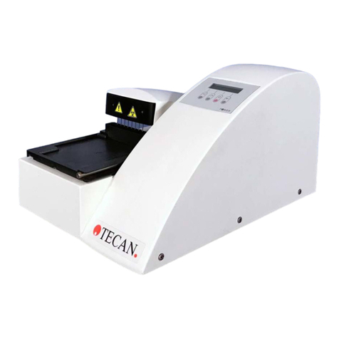
tecan
tecan Columbus Washer User manual

tecan
tecan sunrise RC User manual
tecan
tecan MagicPrep NGS User manual

tecan
tecan sunrise User manual
tecan
tecan GENios User manual
tecan
tecan NanoQuant Plate User manual

tecan
tecan Infinite 200 PRO User manual
tecan
tecan HYDROFLEX PLUS User manual
tecan
tecan Te-Stack 10612253 User manual
tecan
tecan infinite 200 User manual
