BleBox roller gate User manual

rollergate
INTEGRATED ROLLER GATE CONTROLLER
control with μWiFi technology
from any place in the World
values.
Connect only in accordance with the diagram presented in the
with the corresponding electrician’s license.
CONNECTION DIAGRAM
1
Disconnect the installaon supply voltage before installing the controller.
Remember that any mounng works should be carried out when the mains
voltage is disconnected (switch o the mains fuse or disconnect the power
cord from the mains socket).
The controller should be installed in a place protected against adverse
environmental condions. Remember that metallic elements (wires, tubes,
housing parts) have a negave inuence on the range of the device, and
consequently the comfort of use. The controller and electric wires must be
xed permanently to the wall. Due to the operang voltage of the device it
is necessary that the wires are inserted through the rubber glands and the
cable insulaon is cued-out inside the controller housing at a distance of at
least 1 cm from the cable gland. When connecng the wires, make sure that
the insulaon along the enre length of the wire is not damaged. The correct
installaon must guarantee that all conducve elements are protected
against accidental contacts or short circuits, which may cause an electric
shock or damage to the device.
Read the diagram and then proceed to install the controller. Remove the four
screws which x the front panel of the controller and then, holding it on
both sides, pull the panel toward you, which will disconnect the strip of pins
in the connector. Pay special aenon to the designaon of the controller
connectors. Start connecng the power wires: phase L (brown), neutral N
(blue) and the protecve earth PE (yellow-green).
Connect the motor wires: phase MU (black) and MD (brown), N neutral (blue)
and the protecve earth PE (yellow-green).
It is also possible to connect oponal accessories: a warning lamp, addional
wall buons or a wired remote controller, a sensing edge and an infrared
sensor. The ashing warning lamp, supplied with a voltage of 230 V, must be
connected to the terminals LP and N. The addional monostable pushbuons
must be connected between the terminal CM and, corresponding, BU
(“”open”” buon), BD (“”close”” buon), BS (“”stop”” buon), BT (“”step-by-
step”” buon) terminals. The opcal rubber sensing edge with PWM output
interface (50%@500..1500 Hz), must be connected to the terminals V+
(brown), SE (green) and CM (white). The detecon of an obstacle by the
sensing edge or its failure should result in the loss of the PWM signal at the
SE terminal. The set of infrared beam NPN-NC sensor must be connected
to terminals V+ (power “”+”” of infrared sensor), CM (power “”GND”” of
infrared sensor) and IR (normally closed IR sensor output). The detecon of
an obstacle by the infrared sensor or the failure of the photocells (e.g. due to
the damaged wire of the photocell) should cause a break in the IR-CM circuit.
Remove the pinhead from the front panel (if it is in a socket) and insert it into
the socket in the controller board. Holding the front panel of the controller
on both sides, place it carefully and gently to the controller housing, paying
aenon to the correct inseron of the pinheads to the socket. Pay aenon
that the pins does not move horizontaly during the assembly of the panel.
Tighten gently the four screws that secure the front panel - take care not to
use too much force which could damage the housing.
user manual

Go to “Sengs” (icon in the upper right corner of the screen) to the “Door
security sengs” secon. Set the appropriate values in the elds “Enable
infrared sensors” and “Enable sensing edge” according to the connected
safety devices. Remember that the absence of safety devices connected to
the controller, such as infrared sensors and a sensing edge or warning signal
device, can cause damage to health and property! Save the conguraon by
pressing the “Save” buon.
Check the operaon of the controller by pressing the up and down buon
on the keyboard panel: the controller will illuminate the panel and the roller
door will begin to move. Stop the door by pressing the center buon on the
keyboard panel. If the door moves in the opposite direcon to the one given,
go to the conguraon in the “Door” secon and select “Yes” in the opon
“Change the movement direcon”. Remember to save the conguraon by
clicking on the “Save” buon. Press the buons on the keyboard panel to
check again if the door moves as expected.
If the controlled door has a motor with mechanical limit switches or with
electronic limit switches, it is recommended to calibrate the controller by
clicking on the “Automac calibraon” buon in the “Calibraon” secon.
Aer conrming the procedure, the door will automacally rise to the upper
end posion, then go down to the lower end posion and rise to the upper
end posion. Do not take any acon during the calibraon. To check the
work of the control to a point, go to the control screen, and then move the
horizontal scroll bar to the extreme and intermediate posions, verify that
the door moves to the posion set in the animaon. You can also set the
paral opening posion of the door (called venlaon funcon). To do this,
go to the conguraon of the “Door” secon, select the opon “Enable
paral opening” and, in the “Paral opening posion” eld, enter the value
from the range 0-100. By clicking on the “Test” and “Move to” buons, the
door should move in the desired posion. Save the conguraon by pressing
the “Save” buon. Check the funconality: go to the control screen, move
the door to the closed posion and then click on the parally open door
icon (the second icon on the le). The door must be placed in the previously
set posion (the door will not move if the current posion is higher than the
saved posion of the venlaon funcon).
If the controlled door has an unusual motor that does not pass the automac
calibraon procedure, set the “Time limit in seconds” to dene the maximum
me the door needs to move from one end posion to the other: this is the
me when the controller gives voltage to the motor. It is not recommended
to desacvate the movement me limit. In the case that the automac
calibraon has been carried out, the suggested value can be le.
Familiarize yourself with the control screen: the clicking on the door icon
located in the center will cause the following acon in the diagram: raise,
stop, down, stop. If the door is calibrated, the border around it shows the
current posion: the total lling with blue color means the closed posion,
the total lling with grey shows the open posion. Under the door icon,
will be displayed messages about the current status of the door, including
messages from the security system. Lower is the scroll bar to set the
intermediate posion of the door, which is acve only when the door has
been calibrated. At the boom of the screen are the control buons, from le
to right: close, paral open, stop and open. Under the buons, is displayed
an addional warning for emergency situaons, for example, the detecon of
an object through the infrared sensor or the acvaon of the sensing edge.
Aer making sure that the device is connected in accordance with the
diagram, power on the device by connecng the power (turning on the mains
fuse or connecng the power cord to the power outlet).
2
Download the . If you have an Android mobile device,
you will nd the applicaon in the Play Store. For iOS devices the applicaon
is in the App Store.
By using your mobile phone or tablet, connect it to the device wireless
network. To do this, enter to your smartphone or tablet sengs, then go
to seng of the WiFi network and nd the network name „rollerGate-
xxxxxxxxxx” where xxxxxxxxxx is the serial number of the device. Connect
to this network.
Open the wBox applicaon. A device will appear at the top of the screen. To
add it to the applicaon, click on “+” on the right side of the name. To pre-
congure the controller, click on the default device name.
Once you turn on the controller for the rst me, you can proceed to its
further conguraon. Being connected to the WiFi network emied by the
device, in the control panel of the wBox applicaon select the device, then
go to “Sengs” (icon at the top-right corner of the screen).
supply voltage 230V AC
< 1W
control outputs 2 x relay, push-pull, NO;
5A/1250VA
signaling outputs 1 x realy, NO 5A/1250 VA
control inputs 4 x logical, shorted to COM,
12 - 24V DC galvanically separated
supported switches monostable (push-buon),
not-illuminated
security entrances
1 x barrier logic input infrared NPN-
NC, input PWM rubber opcal signal
pressure bar with a frequency of 1 kHz
±50% and 50% duty, 12 - 24 DC,
galvanically separated
15V DC / max. 1.2W
3 - buon, capacive (touch),
illuminated, integrated
in the front panel
housing
surface juncon box, controller covered
with a polyurethane composion not
containing halogens, self-exnguishing
for thermal class B (130 °C)
IP44
dimensions 129 x 89 x 57 mm
transmission type bi-direconal, encrypted
μWiFi, compable with WiFi, 802.11g
mode
direct connecon (as Access Point),
Wi-Fi connecon via a standard router,
connecon with access from any loca-
on in the world (requires only access to
the Internet)
You can also set the conguraon using the web
browser of your phone / tablet. Aer connecng to the
wireless network of the controller, turn on the browser
and go website www.blebox.eu
3
You can change the name of the device that is displayed in the wBox
applicaon. In addion, you can change the name and password of its
generated WiFi network. Remember that changing the network name or
password will disconnect the device immediately aer you click the “Save”
buon, so re-connect to the device using the newly assigned network name
and password.
You can add the controller to your home WiFi network to control it through
this home network or from anywhere in the World. To do this, in the “Connect”
sengs secon, select a network name from the list and press “Connect”. If
is required, enter the WiFi network password. During the connecon of the
controller to your home network, the phone / tablet may disconnected from
the network. In this case, you will need to reconnect your phone / tablet to
the controller network.
Please remember that in order to control the device outside the local WiFi
network, from anyplace in the World by using the wBox applicaon, the
opon “Remote access enabled” in the controller sengs must be set to
“Yes”.
Once you’ve nished conguring the WiFi network, you can disconnect your
phone/tablet from the controller network and connect your mobile device
directly to your home WiFi network. The control from the wBox applicaon
will work the same way as when the phone / tablet is connected to the
controller network. If the user leaves the local network, for example, leaving
home or using the mobile data, the wBox applicaon will signal this state as
“Remote mode”. In this case, the devices can be controlled, but for security
reasons sengs are not available.

To update the soware in the controller, connect it to your home WiFi
network (see “Access Point and WiFi Network Sengs” secon) which is
connected to the Internet. Go to “Sengs” (icon at the top-right corner of
the screen) and click the “Get new rmware” buon in the nal secon on
sengs. Wait about 1 minute, do not close the interface and don’t perform
other acons. The device will download the latest soware. The soware
version number, hardware version and device idener can be read at the
boom of the sengs screen.
www.blebox.eu
made in Europe
for more informaon visit our website
or send us an email to: inf[email protected]
support is available at support@blebox.eu
supply voltage 230V AC
Apple iPhone, Apple iPad, iPad Mini,
Android, computers and mobile devices
supporng HTML5
from -20°C to +50°C
Other BleBox Controllers manuals
BleBox
BleBox shutterbox DIN User manual
BleBox
BleBox wLightBox v3 User manual
BleBox
BleBox GateBoxPro User manual
BleBox
BleBox wLightBox v2 User manual
BleBox
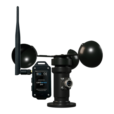
BleBox windsensor PRO User manual
BleBox
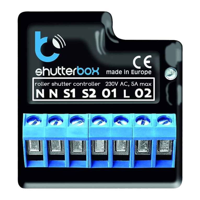
BleBox shutterbox User manual
BleBox
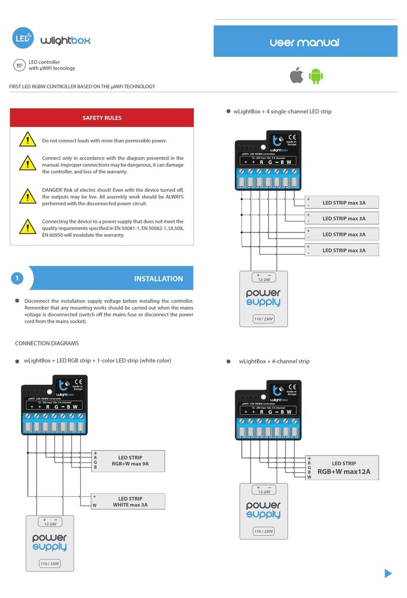
BleBox wLightBox User manual
BleBox
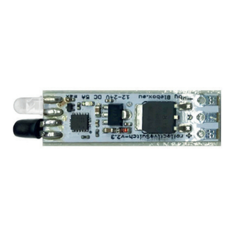
BleBox ReflectiveSwitch User manual
BleBox
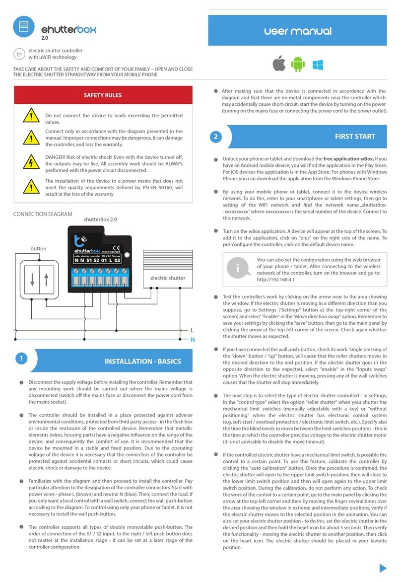
BleBox shutterBox 2.0 User manual

BleBox
BleBox shutterbox User manual
Popular Controllers manuals by other brands
EVSE
EVSE RARON user manual
Frigicoll
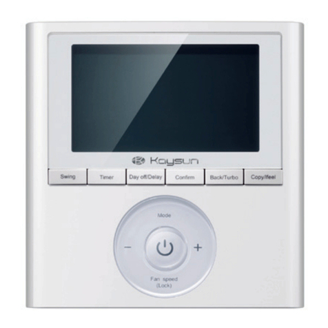
Frigicoll Kaysun KC-03.2 SPS Installation and owner's manual
Performance Motion Devices
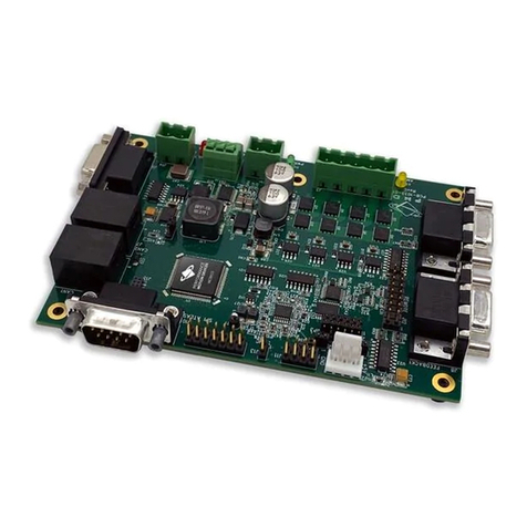
Performance Motion Devices Magellan DK58113 user manual
BTF LIGHTING
BTF LIGHTING SP107E instructions
Ltech
Ltech WiFi-108 manual
CARLO GAVAZZI
CARLO GAVAZZI RSBT Series troubleshooting guide
